Kereskedelmi, irodai és ipari
-
-
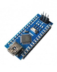
Nano V3.0 Mini USB ATmega328 5V 16M FTDI FT232RL Arduinohoz
1 048 Ft 2 183 Ft100% New, For Arduino-Compatible Board
Fully Compatible for Arduino Nano V3.0 ATmega328P-AU
ATmega328 Microcontroller
Bootloader installed
Microcontroller ATmega328P-AU
Operating Voltage 5V
Input Voltage (recommended) 7V-12V
Input Voltage (limits) 6V-20V
Digital I/O Pins 14 (of which 6 provide PWM output)
Analog Input Pins 8
DC Current per I/O Pin 40 mA
DC Current for 3.3V Pin 50 mA
Flash Memory 32 KB (ATmega328) of which 2 KB used by bootloader
SRAM 2 KB
EEPROM 1 KB
Clock Speed 16 MHz
Size:(Long)45mm *(wide1)18 mm *(high)20mm -
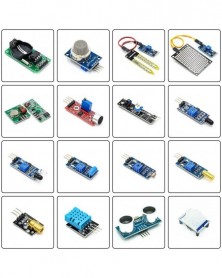
Raspberry Pi 2 3 Generation B 16 szenzorkészletek kísérleti kezdőkészlet
1 058 Ft 2 205 Ft16 sensor modules for Raspberry pi
Shipping list:
DHT11 Temperature and Humidity Module Sensor
HC-SR501 Human Body Infrared Sensing Module
DS1302 real-time clock module without battery
Raindrop Sensor/Module Rain Weather Module
sound sensor module
HC-SR04 Ultrasonic Sensor
Flame sensor module Fire source detection
KY-008 Laser Head Sensor Module
Photoresistor Sensor Module Photoelectric Sensor
YL-69 Soil Moisture Sensor
Obstacle avoidance sensor Barrier car Black and white line recognition
Vibration sensor module Vibration switch
MQ-2 Gas Sensor Module Smoke Module
315M wireless transceiver module 315M super regeneration
Tilt sensor module Tilt switch
One way tracing module Tracing module TCRT5000
DHT11 Temperature and Humidity Module Sensor
HC-SR501 Human Body Infrared Sensing Module
DS1302 real-time clock module without battery
Raindrop Sensor/Module Rain Weather Module
Sound sensor module
HC-SR04 Ultrasonic Sensor
Flame sensor module Fire source detection
KY-008 Laser Head Sensor Module
Photoresistor Sensor Module Photoelectric Sensor
YL-69 Soil Moisture Sensor
Obstacle avoidance sensor Barrier car Black and white line recognition
Vibration sensor module Vibration switch
MQ-2 Gas Sensor Module Smoke Module
315M wireless transceiver module 315M super regeneration
Tilt sensor module Tilt switch
One way tracing module Tracing module TCRT5000 -
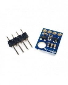
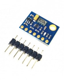
GY-SGP30 gázérzékelő levegőminőség TVOC ECO2 szén-dioxid CO2 IIC I2C 3,3V 5V SGP30 mérőérzékelő formaldehid modul
1 033 Ft 2 152 FtSGP30 is a metal oxide gas sensor with multiple sensing elements on a single chip. It integrates 4 gas sensing elements and has a fully calibrated air quality output signal. In addition, SGP is easy to integrate and can integrate metal oxide gas sensors into mobile devices, opening up new possibilities for environmental monitoring in smart homes, home appliances, and IoT applications. Mainly used for the detection of formaldehyde!
Features:
1. The supply voltage is 3.3V or 5V;
2. IIC communication interface,
3. Use imported high-sensitivity SGP30 formaldehyde sensor, chip power supply voltage is 1.8V;
4. The design is compact and practical;
5. Power consumption 40mA;
6. The onboard 1.8V LDO chip powers the SGP30, so the input power can be 3.3V or 5V.
7.Color:blue
8.size: 13 *10*2.5mm
Product pins: VCC (3.3-5V), GND, SCL, SDA (4 pins in total)
Product Usage:
The SGP30 module can be used for air quality detectors, formaldehyde detectors, portable gas detectors, various DIY designs, etc. -
Szín: ADS1232 - ADS1232 modul 24 bites ADC ultraalacsony zajszintű analóg-digitális átalakító ADS1232IPWR
940 Ft 1 958 FtDescription
The ADS1232 and ADS1234 are precision 24-bit analog-to-digital converters (ADCs). With an onboard, low-noise programmable gain amplifier (PGA), precision delta-sigma ADC and internal oscillator, the ADS1232/4 provide a complete front-end solution for bridge sensor applications including weigh scales, strain gauges and pressure sensors.
The input multiplexer accepts either two (ADS1232) or four (ADS1234) differential inputs. The ADS1232 also includes an onboard temperature sensor to monitor ambient temperature. The onboard, low-noise PGA has a selectable gain of 1, 2, 64, or 128 supporting a full-scale differential input of ±2.5V, ±1.25V, ±39mV, or ±19.5mV. The delta-sigma ADC has 23.5-bit effective resolution and is comprised of a 3rd-order modulator and 4th-order digital filter. Two data rates are supported: 10SPS (with both 50Hz and 60Hz rejection) and 80SPS. The ADS1232/4 can be clocked externally using an oscillator or a crystal. There is also an internal oscillator available that requires no external components. Offset calibration is performed on-demand and the ADS1232/4 can be put in a low-power standby mode or shut off completely in power-down mode. All of the features of the ADS1232/4 are operated through simple pin-driven control. There are no digital registers to program in order to simplify software development. Data are output over an easily-isolated serial interface that connects directly to the MSP430 and other microcontrollers.
The ADS1232 is available in a TSSOP-24 package and the ADS1234 is in a TSSOP-28. Both are fully specified from -40°C to 105°C.
Features
Complete Front-End for Bridge Sensors
Up to 23.5 Effective Bits
Onboard, Low-Noise PGA
RMS Noise:17nV at 10SPS (PGA = 128);44nV at 80SPS (PGA = 128)
19.2-Bit Noise-Free Resolution at Gain = 64
Over 100dB Simultaneous 50Hz and 60Hz Rejection
Rejction
Flexible Clocking:Low-Drift Onboard Oscillator (±3% ); Optional External Crystal
Selectable Gains of 1, 2, 64, and 128
Easy Ratiometric Measurements-External Voltage Reference up to 5V
Selectable 10SPS or 80SPS Data Rates
Two-Channel Differential Input with Built-In Temperature Sensor (ADS1232)
Four-Channel Differential Input (ADS1234)
Simple Serial Digital Interface
Supply Range: 2.7V to 5.3V
-40°C to 105°C Temperature Range
Applications
Weigh Scales
Strain Gauges
Pressure Sensors
Industrial Process Control -
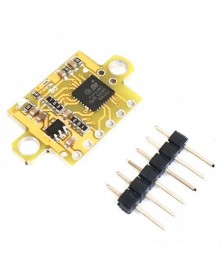
Szín: GY-56 VL53L0X - 1 DB GY-56 VL53L0X VL53L1X Repülési idő (ToF) Infravörös lézer hatótávolság-érzékelő modul
648 Ft 1 350 FtGY-56 infrared laser ranging module serial port or IIC communication, with distance setting switch output high and low level.
Optical cover sheet description: The optical cover sheet supporting VL53L0X VL53L1X can be used to measure more accurately, and at the same time it can protect the sensor and prolong the service life of the sensor. Customers can choose and match by themselves.
Overview
GY-56 is a low-cost digital infrared ranging sensor module. The working voltage is 3-5v, the power consumption is small, the volume is small, and the installation is convenient. Its working principle is that the infrared LED emits light, after illuminating the object under test, the return light is received by the MCU, and the MCU calculates the time difference to obtain the distance. Output the distance value directly.
This module has two ways to read data, namely serial port UART (TTL level) IIC (2-wire) mode. The baud rate of the serial port is 9600bps and 115200bps, configurable, continuous, and query output. Save the settings after power-off. Provide Arduino, 51, stm32 single-chip communication program, do not provide the schematic diagram and internal single-chip source code.
GY-56 can set the upper and lower limit distance alarm value, switch output, and directly output high level when the object is blocked in the set interval. In IIC mode, if necessary, you can set the internal IIC address to be different, so that multiple sensors are directly connected to the same bus.
Features
(1) High-cost performance
(2) Built-in MCU to calculate distance
(3), IIC, serial communication format
(4) Equipped with corresponding upper computer software
Application
(1) Intelligent robot
(2) Teaching laboratory equipment
(3) Product inspection of the production line
(4) Infrared ranging
Technical Parameters
Name
Parameter
Measuring range
0-2 meters (dark light, long-distance mode)
Response frequency
22ms (fast measurement mode)
Working voltage
3~5V
Working current
15~35mA
Working temperature
-20℃ ~ 85℃
Storage temperature
-40℃~ 125℃
Storage temperature
25mm*15.6mm
Sensor chip
VL53L0X -
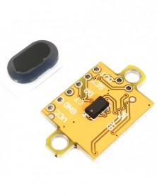
Szín: GY-56L VL53L0X plus - 1 DB GY-56 VL53L0X VL53L1X Repülési idő (ToF) Infravörös lézer hatótávolság-érzékelő
955 Ft 1 990 FtGY-56 infrared laser ranging module serial port or IIC communication, with distance setting switch output high and low level.
Optical cover sheet description: The optical cover sheet supporting VL53L0X VL53L1X can be used to measure more accurately, and at the same time it can protect the sensor and prolong the service life of the sensor. Customers can choose and match by themselves.
Overview
GY-56 is a low-cost digital infrared ranging sensor module. The working voltage is 3-5v, the power consumption is small, the volume is small, and the installation is convenient. Its working principle is that the infrared LED emits light, after illuminating the object under test, the return light is received by the MCU, and the MCU calculates the time difference to obtain the distance. Output the distance value directly.
This module has two ways to read data, namely serial port UART (TTL level) IIC (2-wire) mode. The baud rate of the serial port is 9600bps and 115200bps, configurable, continuous, and query output. Save the settings after power-off. Provide Arduino, 51, stm32 single-chip communication program, do not provide the schematic diagram and internal single-chip source code.
GY-56 can set the upper and lower limit distance alarm value, switch output, and directly output high level when the object is blocked in the set interval. In IIC mode, if necessary, you can set the internal IIC address to be different, so that multiple sensors are directly connected to the same bus.
Features
(1) High-cost performance
(2) Built-in MCU to calculate distance
(3), IIC, serial communication format
(4) Equipped with corresponding upper computer software
Application
(1) Intelligent robot
(2) Teaching laboratory equipment
(3) Product inspection of the production line
(4) Infrared ranging
Technical Parameters
Name
Parameter
Measuring range
0-2 meters (dark light, long-distance mode)
Response frequency
22ms (fast measurement mode)
Working voltage
3~5V
Working current
15~35mA
Working temperature
-20℃ ~ 85℃
Storage temperature
-40℃~ 125℃
Storage temperature
25mm*15.6mm
Sensor chip
VL53L0X -
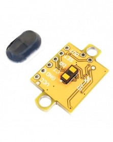
Szín: GY-56L1 VL53L1X plus - 1 DB GY-56 VL53L0X VL53L1X Repülési idő (ToF) Infravörös lézer hatótávolság-érzékelő
1 205 Ft 2 510 FtGY-56 infrared laser ranging module serial port or IIC communication, with distance setting switch output high and low level.
Optical cover sheet description: The optical cover sheet supporting VL53L0X VL53L1X can be used to measure more accurately, and at the same time it can protect the sensor and prolong the service life of the sensor. Customers can choose and match by themselves.
Overview
GY-56 is a low-cost digital infrared ranging sensor module. The working voltage is 3-5v, the power consumption is small, the volume is small, and the installation is convenient. Its working principle is that the infrared LED emits light, after illuminating the object under test, the return light is received by the MCU, and the MCU calculates the time difference to obtain the distance. Output the distance value directly.
This module has two ways to read data, namely serial port UART (TTL level) IIC (2-wire) mode. The baud rate of the serial port is 9600bps and 115200bps, configurable, continuous, and query output. Save the settings after power-off. Provide Arduino, 51, stm32 single-chip communication program, do not provide the schematic diagram and internal single-chip source code.
GY-56 can set the upper and lower limit distance alarm value, switch output, and directly output high level when the object is blocked in the set interval. In IIC mode, if necessary, you can set the internal IIC address to be different, so that multiple sensors are directly connected to the same bus.
Features
(1) High-cost performance
(2) Built-in MCU to calculate distance
(3), IIC, serial communication format
(4) Equipped with corresponding upper computer software
Application
(1) Intelligent robot
(2) Teaching laboratory equipment
(3) Product inspection of the production line
(4) Infrared ranging
Technical Parameters
Name
Parameter
Measuring range
0-2 meters (dark light, long-distance mode)
Response frequency
22ms (fast measurement mode)
Working voltage
3~5V
Working current
15~35mA
Working temperature
-20℃ ~ 85℃
Storage temperature
-40℃~ 125℃
Storage temperature
25mm*15.6mm
Sensor chip
VL53L0X -
Szín: GY-56L1 VL53L1X - 1 DB GY-56 VL53L0X VL53L1X Repülési idő (ToF) Infravörös lézer hatótávolság-érzékelő modul
1 122 Ft 2 337 FtGY-56 infrared laser ranging module serial port or IIC communication, with distance setting switch output high and low level.
Optical cover sheet description: The optical cover sheet supporting VL53L0X VL53L1X can be used to measure more accurately, and at the same time it can protect the sensor and prolong the service life of the sensor. Customers can choose and match by themselves.
Overview
GY-56 is a low-cost digital infrared ranging sensor module. The working voltage is 3-5v, the power consumption is small, the volume is small, and the installation is convenient. Its working principle is that the infrared LED emits light, after illuminating the object under test, the return light is received by the MCU, and the MCU calculates the time difference to obtain the distance. Output the distance value directly.
This module has two ways to read data, namely serial port UART (TTL level) IIC (2-wire) mode. The baud rate of the serial port is 9600bps and 115200bps, configurable, continuous, and query output. Save the settings after power-off. Provide Arduino, 51, stm32 single-chip communication program, do not provide the schematic diagram and internal single-chip source code.
GY-56 can set the upper and lower limit distance alarm value, switch output, and directly output high level when the object is blocked in the set interval. In IIC mode, if necessary, you can set the internal IIC address to be different, so that multiple sensors are directly connected to the same bus.
Features
(1) High-cost performance
(2) Built-in MCU to calculate distance
(3), IIC, serial communication format
(4) Equipped with corresponding upper computer software
Application
(1) Intelligent robot
(2) Teaching laboratory equipment
(3) Product inspection of the production line
(4) Infrared ranging
Technical Parameters
Name
Parameter
Measuring range
0-2 meters (dark light, long-distance mode)
Response frequency
22ms (fast measurement mode)
Working voltage
3~5V
Working current
15~35mA
Working temperature
-20℃ ~ 85℃
Storage temperature
-40℃~ 125℃
Storage temperature
25mm*15.6mm
Sensor chip
VL53L0X -
Léptetőmotoros meghajtó modul tesztkeret hibakereső tesztkártya bővítőkártya 4988, DRV8825, TMC2208, TMC2100, TMC2130
1 085 Ft 2 260 FtThis test frame is suitable for stepper motor drive modules commonly used in the market: A4988, DRV8825, TMC2208, TMC2100, TMC2130, LV8729, etc. The drive module needs to be purchased separately without delivery.
Instructions for use:
Description of Figure 1:
1. VCC: Connect to an external power supply to supply power to the board and stepper motor, and supply power according to the operating voltage of the stepper motor.
2. GND: Connect to the power ground.
3. Configure the port: when the jumper is not added, the EN pin is pulled down to the ground by default, and other ports are pulled up to 5V by default. It can be configured to connect to VDD or GND according to the jumper .
4. VDD power indicator light, when power on, it means that VDD=5V has output.
5. Work indicator, always on means that the single-chip microcomputer outputs pulses with 50% duty cycle of PWM to the pin; the single-chip microcomputer is connected to the STEP port through the R3 resistor by default. If you want to provide PWM pulses externally, you can remove the R3 resistor and then connect to the external PWM pulses.
6. Motor speed adjustment buttons: K1: Long press the frequency to continuously slow down, K2: Long press the frequency to continuously increase, K3: Press once to slow down the frequency, K4: Press once to make the frequency faster. K1 K2 is equivalent to speed continuous adjustment, K3 K4 is equivalent to speed fine adjustment. Restore the default frequency after power failure.
7. The MCU program update port. If you want to write a program to control the motor, you can update the MCU through this port. But no technical support is provided.
8. Stepper motor interface: connect to the stepper motor.
Description of Figure 2
1. The stepper motor drive module VDD is powered, and it is connected to the 5V of the board through a 0R resistor.
2. The stepper motor drive module VM is powered and connected to the VCC power supply through a 0R resistor.
Description of Figure 3
1. The EN pin pull-down resistor is enabled by default, and the jumper cap connected to the VDD module does not work.
2, 3, 4, subdivided pin pull-up resistor, the default is connected to the pull-up to VDD. Set the subdivision according to different motor drive modules. Some modules have only two subdivision pins, only two need to be configured, and the other one does not care about it.
5. The RESET pin pulls up the resistor, and the module does not work when the jumper is connected to GND. Some modules don't have this pin, don't care about it.
6. SLEEP pin pull-up resistor, the module does not work when the jumper is connected to GND. Some modules don't have this pin, don't care about it. Note: The SLEEP and RESET pins of some modules are connected , and only one pin needs to be configured.
7. DIR pin pull-up resistor, forward and reverse settings, jumper cap not connected or connected to VDD reverse, jumper grounded and forward. -
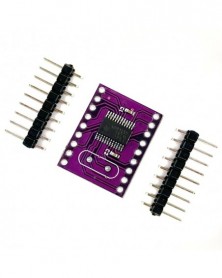
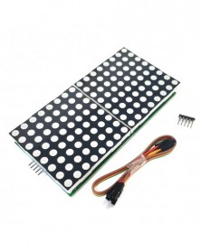
Szín: EGY - MAX7219 nagy pontmátrix 2088AS meghajtó kijelző modul 60*60mm pontmátrix mikrokontroller vezérlő meghajtó
768 Ft 1 599 FtThis module is equipped with a 60*60mm, 2088as. 8*8 dot matrix. The area of this dot matrix is four times that of the commonly used 1088 dot matrix, the characters are bigger and clearer, and it is more suitable for long-distance display. The driver board uses the MAX7219 chip, and is designed with a vertical and horizontal interface that can be cascaded horizontally or vertically.
MAX7219 is an integrated serial input/output common-cathode display driver. It connects a microprocessor and an 8-digit 7-segment digital LED display. It can also be connected to a bar graph display or 64 independent LEDs. It includes an on-chip B-type BCD encoder, multiple scan loops, segment word drivers, and an 8*8 static RAM to store each data. There is only one external register used to set the segment current of each LED.
A convenient four-wire serial interface can be connected to a general-purpose microprocessor. Each data can be addressed without rewriting all the displays when updating. MAX7219 also allows users to select encoding or not encoding for each data.
The entire device includes a 150μA low-power shutdown mode, analog and digital brightness control, a scan limit register allowing users to display 1-8 bits of data, and a detection mode that allows all LEDs to emit light.
Only 3 IO ports can drive 1 dot matrix! No flicker during dot matrix display! Support cascading!
Module parameters:
1. A single module can drive an 8*8 common cathode matrix
2. Module working voltage: 5V
3. Module size: single 60*60MM, two in one 120*60MM, four in one 240*60MM
4. With fixing screw holes, the diameter is 3MM
5. Module with input and output interface, support multiple module cascade
Wiring instructions:
1. The left side of the module is the input port, and the right side is the output port.
2. When controlling a single module, you only need to connect the input port to the CPU
3. When multiple modules are cascaded, the input terminal of the first module is connected to the CPU, the output terminal is connected to the input terminal of the second module, the output terminal of the second module is connected to the input terminal of the third module, and so on. ..
Take 51 single chip microcomputer as an example:
VCC → 5V
GND → GND
DIN → P2.0
CS → P2.1
CLK → P2.2
Shipping list:
1. MAX7219 dot matrix module (finished product, with dot matrix, tested)
2.20CM Dupont Line 5P
3. Pin header 2.54-5P, (1 is welded well, 1 is not welded) -
Szín: KÉT - MAX7219 nagy pontmátrix 2088AS meghajtó kijelző modul 60*60mm pontmátrix mikrokontroller vezérlő meghajtó
1 021 Ft 2 127 FtThis module is equipped with a 60*60mm, 2088as. 8*8 dot matrix. The area of this dot matrix is four times that of the commonly used 1088 dot matrix, the characters are bigger and clearer, and it is more suitable for long-distance display. The driver board uses the MAX7219 chip, and is designed with a vertical and horizontal interface that can be cascaded horizontally or vertically.
MAX7219 is an integrated serial input/output common-cathode display driver. It connects a microprocessor and an 8-digit 7-segment digital LED display. It can also be connected to a bar graph display or 64 independent LEDs. It includes an on-chip B-type BCD encoder, multiple scan loops, segment word drivers, and an 8*8 static RAM to store each data. There is only one external register used to set the segment current of each LED.
A convenient four-wire serial interface can be connected to a general-purpose microprocessor. Each data can be addressed without rewriting all the displays when updating. MAX7219 also allows users to select encoding or not encoding for each data.
The entire device includes a 150μA low-power shutdown mode, analog and digital brightness control, a scan limit register allowing users to display 1-8 bits of data, and a detection mode that allows all LEDs to emit light.
Only 3 IO ports can drive 1 dot matrix! No flicker during dot matrix display! Support cascading!
Module parameters:
1. A single module can drive an 8*8 common cathode matrix
2. Module working voltage: 5V
3. Module size: single 60*60MM, two in one 120*60MM, four in one 240*60MM
4. With fixing screw holes, the diameter is 3MM
5. Module with input and output interface, support multiple module cascade
Wiring instructions:
1. The left side of the module is the input port, and the right side is the output port.
2. When controlling a single module, you only need to connect the input port to the CPU
3. When multiple modules are cascaded, the input terminal of the first module is connected to the CPU, the output terminal is connected to the input terminal of the second module, the output terminal of the second module is connected to the input terminal of the third module, and so on. ..
Take 51 single chip microcomputer as an example:
VCC → 5V
GND → GND
DIN → P2.0
CS → P2.1
CLK → P2.2
Shipping list:
1. MAX7219 dot matrix module (finished product, with dot matrix, tested)
2.20CM Dupont Line 5P
3. Pin header 2.54-5P, (1 is welded well, 1 is not welded) -
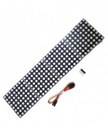
Szín: NÉGY - MAX7219 nagy pontmátrix 2088AS meghajtó kijelző modul 60*60mm pontmátrix mikrokontroller vezérlő meghajtó
1 359 Ft 2 832 FtThis module is equipped with a 60*60mm, 2088as. 8*8 dot matrix. The area of this dot matrix is four times that of the commonly used 1088 dot matrix, the characters are bigger and clearer, and it is more suitable for long-distance display. The driver board uses the MAX7219 chip, and is designed with a vertical and horizontal interface that can be cascaded horizontally or vertically.
MAX7219 is an integrated serial input/output common-cathode display driver. It connects a microprocessor and an 8-digit 7-segment digital LED display. It can also be connected to a bar graph display or 64 independent LEDs. It includes an on-chip B-type BCD encoder, multiple scan loops, segment word drivers, and an 8*8 static RAM to store each data. There is only one external register used to set the segment current of each LED.
A convenient four-wire serial interface can be connected to a general-purpose microprocessor. Each data can be addressed without rewriting all the displays when updating. MAX7219 also allows users to select encoding or not encoding for each data.
The entire device includes a 150μA low-power shutdown mode, analog and digital brightness control, a scan limit register allowing users to display 1-8 bits of data, and a detection mode that allows all LEDs to emit light.
Only 3 IO ports can drive 1 dot matrix! No flicker during dot matrix display! Support cascading!
Module parameters:
1. A single module can drive an 8*8 common cathode matrix
2. Module working voltage: 5V
3. Module size: single 60*60MM, two in one 120*60MM, four in one 240*60MM
4. With fixing screw holes, the diameter is 3MM
5. Module with input and output interface, support multiple module cascade
Wiring instructions:
1. The left side of the module is the input port, and the right side is the output port.
2. When controlling a single module, you only need to connect the input port to the CPU
3. When multiple modules are cascaded, the input terminal of the first module is connected to the CPU, the output terminal is connected to the input terminal of the second module, the output terminal of the second module is connected to the input terminal of the third module, and so on. ..
Take 51 single chip microcomputer as an example:
VCC → 5V
GND → GND
DIN → P2.0
CS → P2.1
CLK → P2.2
Shipping list:
1. MAX7219 dot matrix module (finished product, with dot matrix, tested)
2.20CM Dupont Line 5P
3. Pin header 2.54-5P, (1 is welded well, 1 is not welded) -
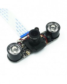
Raspberry Pi 4 Model B/3B /3B/2B Night Vision halszem kamerához, 5 MP OV5647 72 fokos, állítható fókuszú kamerához
967 Ft 2 014 FtFeatures:
1. Fish eye wide angle lens
2. Night vision camera for 72 degree
3. 5 MP pixel
4. Support 1080P resolution
5.Easy to install
Descriptions:
For Raspberry Pi Camera, supports all revisions of the Raspberry Pi
Comes with infrared LED, supports night vision
Specifications:
Raspberry Pi Camera
5 megapixel OV5647 sensor
Camera specifications
CCD size : 1/4inch
Sensor best resolution : 1080p
4 screw holes
Used for attachment
Focal Length : 2.1
Diagonal angle : 130 degree / 160 degree
Provides 3.3V power output
Dimension: 25mm x 24mm
Package included:
1 x Raspberry Pi camera
2 x Infrared LED Lights
1 x 15cm FPC cable
Notes:
1. Please allow 1-3cm measure error.
2. The color of the actual items may slightly vary from the above images due to different computer screen, thanks for your understanding. -
PAJ7620U2 Különféle gesztusfelismerő érzékelő modul Arduino PAJ7620-hoz Beépített 9 gesztusos IIC interfész
499 Ft 1 039 FtProduct introduction:
This product is based on the PAJ7620U2 gesture recognition sensor, which can recognize gestures in 9 different directions, including up, down, left, right, front, back, clockwise, counterclockwise, and swing. The gesture recognition module uses the II2C interface and can be programmed and controlled by using the corresponding Arduino library functions. The signal returned by the gesture recognition module can be used as the control signal received by the robot to realize the control of the robot. The built-in recognition algorithm is quite powerful and can free your hands from rigid buttons. Gesture recognition sensors can be used in non-contact control scenarios such as a non-contact mouse, smart homes, car click device control, robot interaction, etc.
Product Features:
1.9 gesture recognition
2. Interface: IIC interface communication protocol
3. Working voltage: 3.3V-5.0V
4. The gesture speed is 60°/S to 600°/S in normal mode and 60°/S to 1200°/S in game mode
5. Ambient light immunity: <100K Lux
6. Working current: 3mA-10mA
7. Module size: 20mm*15mm
Interface definition:
1. GND: Power negative input port
2. VCC: Power supply positive input port
3. SCL: I2C clock port
4. SDA: I2C data port
5.INT: interrupt output
Wiring distance: 2.54mm (round distance between two holes) -
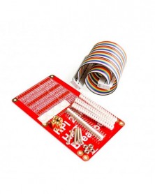
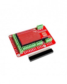
Kompatibilis a Raspberry Pi Raspberry pi A /B /2 generációs HAT GPIO kábelbővítő kártya fejlesztőkártyával
975 Ft 2 032 FtDescription
The RPI HAT extension version allows you to build an extension circuit with HAT, and supports Raspberry Pi B /A /Pi 2. It includes HAT debug circuit, or you can install other HAT specification extension plug-ins.
Features:
HAT compatible
40P cable can be installed
Label all pin functions, BCM labels, and peripheral multiplexing.
Anti-slip pad
4 screw holes
Kit not installed
Shipping list:
1: 1 rainbow cable
2: 1 GPIO HAT expansion board
3: 2*20 array, 4 groups
4: 1 set of fixing screws and nuts -
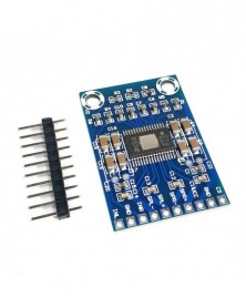
XH-M562 ultra-mikro verzió TPA3116D2 digitális audio erősítő kártya D osztályú végerősítő kártya ultravékony
928 Ft 1 933 FtProduct name: TDA3116D2 digital amplifier board
Product model: XH-M562
Power supply voltage: DC12-DC24V
Output channel: two channels
Product size: 37.2*25.6MM -
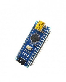
Szín: 328P-AU hegesztés nélkül - Nano V3.0 CH340G továbbfejlesztett változat Atmega328P fejlesztői kártya Arduinohoz
1 003 Ft 2 090 FtCH340 USB Driver, atmega328P main IC, bootload has been written to the board.
CH340C Replace FT232RL
8 analog inputs ports: A0 ~ A7
14 Digital input / output ports:TX,RX,D2 ~ D13
6 PWM ports: D3, D5, D6, D9, D10, D11
1 pair of TTL level serial transceiver ports RX / TX
Using Atmega328 MCU
There is a bootloader installed in it
Support USB download and Power
Support for external 5V ~ 12V DC power supply
Support power supply by 9V battery
Support ISP download -
Szín: 328P-AU Hegesztés - Nano V3.0 CH340G továbbfejlesztett változat Atmega328P fejlesztői kártya Arduinohoz
1 015 Ft 2 115 FtCH340 USB Driver, atmega328P main IC, bootload has been written to the board.
CH340C Replace FT232RL
8 analog inputs ports: A0 ~ A7
14 Digital input / output ports:TX,RX,D2 ~ D13
6 PWM ports: D3, D5, D6, D9, D10, D11
1 pair of TTL level serial transceiver ports RX / TX
Using Atmega328 MCU
There is a bootloader installed in it
Support USB download and Power
Support for external 5V ~ 12V DC power supply
Support power supply by 9V battery
Support ISP download -
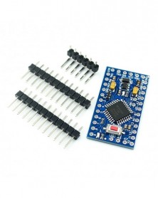
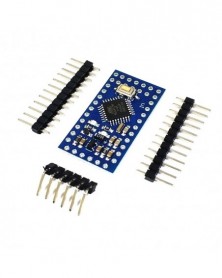
328P -3,3V 8M - ATMEGA328P Pro Mini 328 Mini ATMEGA328 5V/16MHz ATMEGA328 3.3V 8MHz Arduino fejlesztőkártyához
885 Ft 1 843 FtThe professional version of Mini Pro is a microcontroller circuit board. It has 14 digital input/output pins (6 of which can be used as PWM outputs), 8 analog inputs, an 8MHz resonator, a reset button, and mounting hole pin headers.
Technical Parameters:
1. 14 digital input/output ports RX, TX, D2~D13,
2. 8 analog input ports A0~A7
3. 1 pair of TTL level serial port transceiver port RX/TX
4. 6 PWM ports, D3, D5, D6, D9, D10, D11
5. Using Atmel Atmega328P-AU microcontroller
6. Support serial download
7. Support external 3.3V~12V DC power supply
8. Support 9V battery power supply
9. Clock frequency 8MHz
10. Size: 33.3*18.0 (mm) -
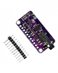
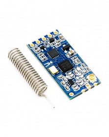
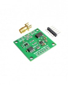
CJMCU-4713 SI4713 sztereó FM adó modul Sztereó FM adó
625 Ft 1 303 FtFeatures
• Integrated receive power measurement
• Worldwide FM band support(76-108MHz)
• Requires only two external components
• Frequency synthesizer with integrated VCO
• Digital stereo modulator
• Programmable pre-emphasis
• Analog/digital audio interface
• Audio silence detector
• Programmable reference clock
• RDS/RBDS encoder (Si4713 only)
• PCB loop and stub antenna support with self-calibratedcapacitor tuning
• Programmable transmit level
• Audio dynamic range control
• Advanced modulation control
• 2.7 to 5.5 V supply voltage
• Integrated LDO regulator
•3×3×0.55mm20- pin QFNPb-free and RoHS Compliant
• Designed for compatibility with cellular operation
Applications
• Cellular handsets/hands-free
•MP3 players
• Portable media players
• Wireless speakers/microphone
• Satellite digital audio radios
• Personal computers/notebooks
Description
TheSi4712/13-B30 integrates the complete transmit functions forstandards-compliant unlicensed FM broadcast stereo transmission. The chip also allows integrated receive power scanning to identify low signal power FM channels. Users must comply with local regulations on radiofrequency(RF)transmission.
Pin description (for reference only):
LIN: Audio input, connect the left channel of the earphone.
RIN: Audio input, connect the right channel of the earphone.
Vin: The power supply voltage is 3-5V DC.
GND: Ground.
3V0: This is the regulator interface, which is connected to a 3.3V voltage. If you need a 3V voltage of 100 mA, you can use this regulator voltage.
RST: Reset.
CS: Select pin, used in spi mode. The i2c address is determined. When connected to high level (default), the i2c address is 0x63. If it is grounded or short-circuited, the i2c address is 0x11.
SCL: Clock pin, connected to the microcontroller.
SDA: Data pin, connected to the microcontroller.
GPIO: can be used to flash the LED, the initial state has been set, 3V output. -
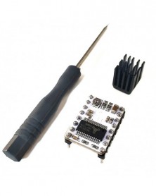
3D nyomtató-tartozékok TMC2130 V1.1 léptetőmotor-illesztőprogram rendkívül csendes meghajtó 256-os felosztás
605 Ft 1 260 FtFeatures:
①Two-phase stepping motor single-phase current 2A (peak 2.5A) motor working current can be adjusted
②Support SPI interface control mode
③Motor input voltage range: 4.75-46V
④The logic interface input voltage is: 3-5V
⑤ subdivided into 256
⑤ Noise-free operation combined with maximum efficiency and best motor torque
⑦High-precision sensorless motor load detection
⑧ Reduce energy consumption by 75% ,
⑨ High load drive without losing a step
TMC2130 is a high-performance two-phase stepper motor driver chip with a standard SPI interface and a simple step/dir interface. The continuous output current is up to 1.2A, and it can withstand a peak current of 2A in a short period of time, with extremely low noise, and high load driving without losing steps.
The SPI working mode of TMC2130-V1.1 can directly select the drive current, drive subdivision, and other parameters through the firmware, making these parameters more accurate; the use of an external sequencer greatly reduces the workload of the chip and effectively avoids the overload of the chip due to the workload. Problems caused by deviations, lost steps, faults, etc.
Drive current algorithm and adjustment
1. Vref measures the voltage between GND and the potentiometer.
2. When measuring the voltage, the power supply should be turned on. Don't just connect the USB power supply.
3. When measuring voltage, be sure not to connect the motor, otherwise, the drive will be burnt easily.
4. Drive current algorithm: i-Vref*1.9/2.5, the default Vref is about 1V, so the default current is 0.76A, and the maximum current is 2A! Please pay special attention to the direction and do not plug it in reverse! -
Pro mini továbbfejlesztett verzió ATMEGA328P 5V/16M elektronikus építőelem modul interaktív média
885 Ft 1 843 FtThe product is shipped with a boot program. When the customer writes a program to change, it is recommended not to use the format method, so that the boot program will be formatted. There is an option (code repair and reload) in the software tool, which can be used when rewriting the program This one.
The professional version of Mini Pro is a microcontroller circuit board. It has 14 digital input/output pins (6 of which can be used as PWM outputs), 8 analog inputs, a 16MHz resonator, a reset button, and mounting hole pin headers.
Technical Parameters:
1. 14 digital input/output ports RX, TX, D2~D13,
2. 8 analog input ports A0~A7
3. 1 pair of TTL level serial port transceiver port RX/TX
4. 6 PWM ports, D3, D5, D6, D9, D10, D11
5. Using Atmel Atmega328P-AU microcontroller
6. Support serial download
7. Support external 3.3V~12V DC power supply
8. Support 9V battery power supply
9. Clock frequency 16MHz
10. Size: 33.3*18.0 (mm) -
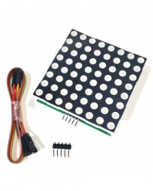
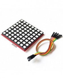
LED Full Color Dot Matrix RGB LED kijelző kártya 8*8 Dot Matrix modul Raspberry Pi 3/2/B 8x8 RPI-RGB-LED-Matrixhoz
904 Ft 1 883 FtRPI-RGB-LED-Matrix This 8x8 RGB full color dot matrix screen is a useful dot matrix screen developed based on 74HC595 chip, it is compatible with almost all development boards, such as: Arduino series, Raspberry Pi, banana Pi , as well as the STM32 series and 51 microcontrollers.
It uses the SPI protocol to communicate with the microcontroller or development board, and has the characteristics of fast speed and convenient operation.
It is widely used by makers in various makerspaces for art display, warning reminders and other identification products. Some people even use its high-brightness feature to make music spectrum analyzers and bicycle tail lights.
· Based on 74HC595 chip
· Support SPI protocol
· Low power consumption
· RGB full color support
How to connect:
Please refer to the following table and the following diagrams for the wiring method. All wiring requires only 5 wires, namely VCC, GND, CE, MOSI, and SCLK.
Wiring table:
Raspberry Pi
RPI-RGB-LED-Matrix
5V
VCC
GND
GND
GPIO11(BCM)
CLK
GPIO8(BCM)
CE
GPIO10(BCM)
MOSI
How to drive:
1. All operations here are based on the assumption that you have completed the burning of the Raspberry Pi operating system. If you have not yet burned the system, please refer to the relevant documentation of the burning system in wiki.52pi.com. of burning.
2. First log in to the system and open a terminal, then edit the /boot/config.txt file with the following command to enable the SPI function.
sudo vim.tiny /boot/config.txt
Enter the following parameters:
device_tree=bcm2710-rpi-3-b.dtb
dtparam=spi=on
Save and exit, reboot the Raspberry Pi.
2. Edit a file and name it matrix.c, then fill in the following C language code and save and exit.
sudo vim.tiny matrix.c
Enter the following:
#include
#include
#include
#include
#define RED_DATA 0
#define BLUE_DATA 1
#define GREEN_DATA 2
int main(void)
{
static uint8_t data[4] = {0x0,0x0,0x0,0x0};
wiringPiSetup();
wiringPiSPISetup(0,500000);
while(1)
{
static uint8_t heart[8] = {0x00, 0x66, 0xFF, 0xFF, 0xFF, 0x7E, 0x3C, 0x18};
int j;
int x=2;
for (j=0;j<8;j )
{
data[0] = ~heart[j];
data[2] = 0xFF;
data[1] = 0xFF;
data[3] = 0x01 << j ;
wiringPiSPIDataRW(0,data,sizeof(data));
delay(x);
};
};
}
3. Use the GCC compiler to compile and execute the file to see the effect.
sudo gcc -o matrix matrix.c -lwiringPi
sudo ./matrix -
Kompatibilis a J-Link OB ARM szimulációs hibakereső SWD programozóval STM32 letöltő Jlink Generation v8
896 Ft 1 866 FtProduct Introduction
It is usually designed on the evaluation board ("on-board") of major companies, which is why the suffix is "OB". This set of simulation download debuggers named "ARM-OB" has USB communication function, which can communicate with PC, and the other end communicates with supported devices through SWD/JTAG method to complete the task of debugging simulation download debugging. Compared with the original OB debugger, our ARM OB emulation debugger lacks the JTAG interface and only retains the SWD interface to debug and download the MCUs of many companies that use the ARM core.
Supported kernel
All ARM7911, Cortex-M0M1M2M3M4A5A8A9 series embedded microcontrollers with SWD interface.
Support MCU generation vendors
ST (STMicroelectronics), Freecale (Freescale), nuvoton (Nuvoton), NXP (NXP), TI (Texas Instruments)
Cypress, Atmel, Analog, Fujitsu, Toshiba
Energy Micro, etc.
Connection method
SWD mode
Function, performance
Programming function: Can burn and write FLASH ROM, EEPROM, AFR, etc.
Simulation function: support various debugging methods such as full-speed operation, single-step debugging, breakpoint debugging, etc., and you can view IO status, variable data, etc.
Programming performance: using USB2.0 interface for SWD download, fast download speed!
Simulation performance: using USB2.0 interface for simulation debugging, single-step debugging, breakpoint debugging, fast response speed!
Features
1. The interface is simplified, and the 4-wire SWD interface is adopted:
vcc, swdio, swclk, gnd, can download simulation at high speed.
2. Compatible with the traditional V8 emulator, the functions are completely the same.
3. Use the universal micro USB interface, which is convenient to use (common interface for ordinary Android phones).
4. Supporting 3.3V output, the maximum output current is 300MA, which is convenient for users to debug and download the target board.
5. The new onboard self-recovery fuse has effective short circuit protection and safer debugging.
6. ESD protection devices are more stable.
7. Transparent heat shrinkable tube packaging.
8. The firmware is stable and can be automatically upgraded, and there will be no firmware damage (full-featured v8 has firmware problems).
9. The size of the U disk is convenient for carrying on business trips.
Comparison of J-Link ARM OB and ST-Link v2
Debugger
J-Link ARM OB
ST-Linkv2
Interface method
SWD
SWD/SWIM
Support series
Most ARM core MCUs
ST's STM8 series/STM32 series
Support company
ST,Freecale,NXP,Atmel,TI...etc.
ST
Delivery list: 25g/set
1. 1 ARM OB motherboard
2. 1 high-quality microUSB cable
3. 4PIN SWD download line 1
Interface Description:
SWD interface four wires, VCC (=3.3V), GND, SWDIO (=TMS=DIO), SWCLK (=TCK=CLK) -
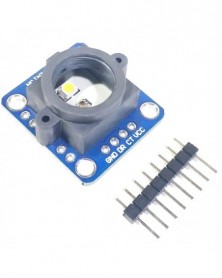
GY-33 TCS34725 színérzékelő Azonosító felismerő érzékelők modul Cserélje ki a TCS230 TCS3200 GY 33 GY33 DIY
613 Ft 1 278 FtCS34725 chip mcu color recognition sensor module, IIC or serial communication, directly output RGB value
1. It can be used as a simple TCS34725 module.
2. You can use the internal MCU to read the TCS34725 data, the MCU directly outputs RGB after calculation, the internal white balance program, and supports serial/IIC reading.
Provide 51 single-chip microcomputers, Arduino single-chip microcomputer, stm32 single-chip microcomputer, (IIC/serial port) communication read data program.
Overview
GY-33 is a low-cost color recognition sensor module. The working voltage is 3-5v, the power consumption is small, the volume is small, and the installation is convenient. Its working principle is that the illuminating LED emits light, and after illuminating the object to be measured, the return light passes through the filter to detect the RGB ratio value, and the color is identified according to the RGB ratio value.
This module has two ways to read data, namely serial UART (TTL level) or IIC (2-wire). The baud rate of the serial port is 9600bps and 115200bps, configurable, continuous, and query output. The settings can be saved after power-off. There are simple 7 kinds of color recognition, no need to calculate RGB value. It can adapt to different working environments and connect with a single-chip microcomputer and computer. The module can also set the operating mode of a separate sensor chip. As a simple sensor module, the MCU does not participate in the data processing. Provide Arduino, 51, stm32 MCU communication program,
The schematic diagram and the source code of the internal microcontroller are not provided.
Features
(1) High-cost performance
(2) Built-in MCU to calculate color
(3), IIC, serial communication format
(4) Adjustable LED brightness
(5), with corresponding upper computer software
Applications
(1) Intelligent robot
(2) Teaching laboratory equipment
(3) Product inspection of the production line
(4), colorimeter
(5), led color detection
Technical Parameters
Name
Parameter
Measuring range
RGB 0-255
Response frequency
10Hz
Working voltage
3~5V
Working current
15mA
Working temperature
-20℃ ~ 85℃
Storage temperature
24.3mm*26.7mm
Sensor chip
TCS34725 -
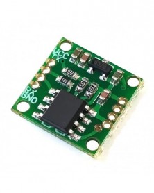
BME280-5V - GY-BME280-5V hőmérséklet és páratartalom érzékelő légköri nyomás érzékelő modul
150 Ft 312 FtGY-BME280-5V is a three-in-one module that integrates temperature, humidity and air pressure
GY-BMP280-5V is an integrated temperature and air pressure two-in-one module
Produced with new original chip, onboard LDO can supply power from 3.3-5V
Description
ME-BME280 is a Breakout Board featuring a Bosch Sensortec ME280 Temperature, Humidity & Pressure Sensor.
The board has a selectable I2C address jumper (solder link GS2), I2C pull-up resistors, 7 pin header 2.54mm, and two mounting holes 3.5mm.
The default setting of the board; single power rail Vdd=Vdd_IO (solder link GS1), pull-ups resistors (R2, R3) 10k, protocol selector resistor 0ohm (R1), decoupling capacitors 0.1uF on both power supply pins Vdd & Vdd_IO.
If you connect the board to both power rails VDD_IO 1.8V and VDD 3.3V be sure to remove the power rail jumper GS1!
BME280 Features
- Package 2.5 mm x 2.5 mm x 0.93 mm metal lid LGA
- Digital interface I2C (up to 3.4 MHz) and SPI (3 and 4 wire, up to 10 MHz)
- Supply voltage VDD main supply voltage range: 1.71 V to 3.6 V
VDDIO interface voltage range: 1.2 V to 3.6 V
- Current consumption 1.8 uA @ 1 Hz humidity and temperature
2.8 uA @ 1 Hz pressure and temperature
3.6 uA @ 1 Hz humidity, pressure, and temperature
0.1 uA in sleep mode
- Operating range -40… 85 C, 0…100 % rel. humidity, 300…1100 hPa- Humidity sensor and pressure sensor can be independently enabled/disabled
Bosch has stepped up their game with their new BMP280 sensor, an environmental sensor with temperature, barometric pressure that is the next generation upgrade to the BMP085/BMP180/BMP183. This sensor is great for all sorts of weather sensing and can even be used in both I2C and SPI!
This precision sensor from Bosch is the best low-cost, precision sensing solution for measuring barometric pressure with ±1 hPa absolute accuracy, and temperature with ±1.0°C accuracy. Because pressure changes with altitude and the pressure measurements are so good, you can also use it as an altimeter with ±1 meter accuracy
The BME280 is the next generation of sensors from Bosch and is the upgrade to the BMP085/BMP180/BMP183 - with a low altitude noise of 0.25m and the same fast conversion time. It has the same specifications but can use either I2C or SPI. For simple easy wiring, go with I2C. If you want to connect a bunch of sensors without worrying about I2C address collisions, go with SPI. -
Szín: STM32G070RBT6 - STM32G070RBT6 fejlesztői tábla minimális rendszer alaplap tanulótábla csere STM32F103/070
498 Ft 1 038 FtDevelopment board introduction
Onboard high-precision 12MHz high-speed crystal oscillator, 32.768KHz low-speed crystal oscillator
Onboard power status display LED, user LED, a reset button and a user button
The IO pins of the development board are all led out
Support 3.3~5V power supply
Development board size 52.3mm*33.3mm
All routines are developed using CubeMX HAL library, which is easy to use and provides MDK (KEIL) project
Provide FreeRTOS routines
Support ISP serial port download, SWD download, etc., provide software packages
Routines are provided as follows -
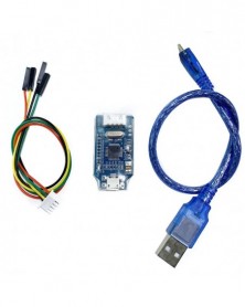
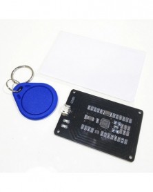
Frissített verzió Mini PN532 soros port modul/NFC/IC kártyaolvasó/replikátor/hozzáférési lift M1 kártyaolvasó/író
655 Ft 1 364 FtDescription:
CUID card instructions and other card categories, 2-5 is a copy card
1.M card: ordinary IC card, 0 sector can not be modified, other sectors can be repeatedly erased, we use elevator cards, access cards and other smart card issuers are M1 card, not copy cards, can be understood as a copy of the card. Taobao presents a M1 blank test card.
2. UID card: ordinary copy card, can repeatedly erase all sectors, encounter the failure of the firewall;
3. CUID Card: Upgrade the replication card, the system that shield the UID replication card can use CUID instead of UID, 70% pass rate. It can erase all sectors repeatedly.
4. FUID card: Advanced replication card, when CUID replication is useless, 0 sector can only be written once, write once to M1 card, 100% of the replication is successful, after writing, other sectors except 0 sector can be erased repeatedly;
5. UFUID card: Advanced copy card, we understand as UID and FUID composite card, need to seal the card operation, change M1 card after sealing, not seal is UID card.
FAQ
1. What cards can the machine copy?
The machine can copy the elevator cards of the entrance guard of the residential area. It can not be used for illegal purposes except this. It does not support the replication of water.
Food Card, Bank Card, Credit Card, Campus Card, etc.
2. Can you change the date, floor and amount data?
The equipment only has the function of cloning and duplicating, and has no function of postponing and changing the amount of money. We can not provide such teaching.
3. Can you copy the parking card of the underground garage in the residential area?
Parking cards can be duplicated. It is necessary to confirm the type of cards and whether to swipe them in or out. If you bring in and out restrictions, the duplicate cards will not be able to enter after the main card is admitted.
4. What is C card and ID card? How to distinguish them?
IC card and D card are two different types of chip cards. Different cards need different machines and replication cards to copy clones. See the details below for the resolution method.
5. Why can't my old card write data?
Common card and replication card are two different kinds of cards. Because the common card chip has been solidified and written to death, it can not write information, so it can not be used as replication card. Replication needs to buy special replication card.
6. Can multiple cards be combined?
There is no way to combine multiple cards. A duplicate empty card can only write the information of one card!
7. The decryption is successful. What's wrong with duplicating and writing cards?
Entrance guard elevator system with firewall identifies and detects replica cards so as to shield them. At this time, special replica cards of firewall type need to be used and locked after writing cards in order to achieve replication effect.
8. Is decryption replication 100% successful?
Because the use of machine replication cards belongs to the technical category, different access elevators in the market use different technologies, most of them can be replicated! But there is no guarantee of 100% success!
Shipment List:
PN532 Serial Port motherboard, 1 piece
CUID White Card, 1
CUID Key Link, 1 -
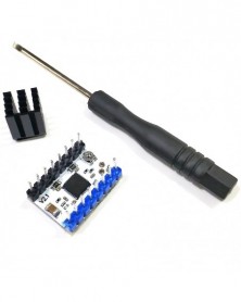
3D nyomtató tartozékok TMC2209 léptetőmotor meghajtó modul ultra-csendes uart TMC2208 frissített verzió
912 Ft 1 900 FtShipping list:
1. TMC2209v3.0 stepper motor driver*1
2. Heat sink*1
3. Screwdriver*1
product description:
TMC2209 is an ultra-quiet motor driver IC (originally imported chip) for two-phase stepper motors. TMC2209 is pin-compatible with many traditional drivers and TMC2208. TRINAMICs' advanced StealthChop2 chopper ensures noise-free operation of the motor, achieving high efficiency and motor torque. The combination of its fast current regulation and resonance suppression function can achieve high dynamic movement. Stallard is used to returning to the origin without a sensor to prevent stalling. The built-in power MOSFET can handle up to 2A RMS motor current , with protection and diagnostic functions, which can achieve stable and reliable operation. An easy-to-use UART interface opens up tuning and control options. Store application tuning in OTP memory. The drive can be set for noise-free operation and very precise operation through a separate pulse direction, thereby realizing a cost-effective and highly competitive solution
TMC series drive comparison table:
1. The operating mode of the TMC2209 V2.1 stealth chip is almost silent.
2. The TMC22209 V2.1 driver has an improved stealth chip mode (stealthChop2), which works better at higher accelerations.
3. Compared with TMC2100, the resistance of the TMC220 output driver (RDSon) is slightly lower, thereby reducing power consumption.
Product parameters:
Hardware compatible with StepStick and Pololu A4988
Drive capability up to 1.7A (RMS) continuous coil current-2.8A Peak
Step/Dir interface with micro step interpolation (up to 256 micro steps)
Configuration via CFG pins or UART interface
Motor voltage: 5.5...28V
Logic voltage: 3.3...5V
RSense: 0.11 Ohm
stealthChop2-for quiet operation and smooth motion
spread cycle-highly dynamic motor control chopper (enable able via UART, OTP, CFG Pin)
cool step-current control for energy savings
stallGuard4-sensorless motor load detection -
AD9833 háromszög szinuszos jelforrás IC integrált áramkör négyszöghullám generátor modul
531 Ft 1 106 FtAD9833 DDS Signal Generator Module 0-12.5MHz Square / Triangle / Sine Wave
Introduction:
AD9833 is a programmable waveform generator, which can generate sine wave, triangle wave and square wave signal with frequency of 0-12.5MHZ. The waveform generator is widely used in various measurement, excitation and time domain response fields. The output frequency and phase can be programmed by software, which is easy to adjust. When the main frequency clock is 25MHz, the precision is 0.1Hz, and when the main frequency clock is 1MHz, the precision Can reach 0.004Hz. Data can be written via 3 serial interfaces.
Application:
Frequency excitation / waveform generation. Liquid, gas flow measurement.
Sensing applications - approximation, sports, defect detection.
Linear loss, linear decay.
Test equipment, medical equipment
Scan clock generator
Features:
1, the working voltage: 2.3V-5.5V.
2, the working temperature range: -40 ~ 105 prefix = o
3, onboard 25MHZ (accuracy of 50ppm) active crystal, stepping accuracy 0.1HZ.
4, on-board high-speed amplifiers 300M and also has a low-pass filtering.
5, two-channel output signal, an original signal output, an amplified output signal 5 times, 50Ohm output impedance.
6, very small size: 32mm X 32mm.
7, support universal plate (tunnel plate), a multiple-board pins are 2.54mm, can be easily welded universal board.
8, distribution STM32, STM8, STC and other common microcontroller debugged program and relevant information. -
GY-SHT31-D - GY-SHT30-D GY-SHT31-D GY-SHT35-D digitális hőmérséklet és páratartalom érzékelő modul I2C kommunikáció
252 Ft 524 FtProduct description:
The new temperature and humidity sensor series SHT3X takes the sensor technology to a new level. The SHT3X series includes a low-cost version SHT30, a standard version SHT31, an I2C interface and a wide operating voltage range (2.4-5.5V)
Technical Parameters:
1. Humidity measurement range: 0~100% RH
2. Humidity measurement accuracy: SHT30 ±3% RH; SHT31 ±2% RH; SHT35 ±1.5% RH;
3. Temperature measurement range: -40~125℃
4. Temperature measurement accuracy: SHT30SHT31±0.3℃SHT35±0.2℃
5. Working voltage: 2.4~5.5VDC (wide voltage)
6. I2C interface output
7. Size: 1.25MM*1MM -
1db RCWL-0801 TOF hatótávolság Vl53l0x lézeres távolságmérő érzékelő modul soros port kimeneti távolság
567 Ft 1 181 FtDescription:
Chip Features
Fully integrated miniature module
940nm Laser VCSEL
VCSEL driver
Ranging sensor with advanced embedded micro controller
4.4 x 2.4 x 1.0mm
Fast, accurate distance ranging
Measures absolute range up to 2m
Reported range is independent of the target reflectance
Operates in high infrared ambient light levels
Advanced embedded optical cross-talk compensation to simplify cover glass selection
Eye safe
Class 1 laser device compliant with latest standard IEC 60825-1:2014 - 3rd edition
Easy integration
Single reflowable component
No additional optics
Single power supply
I2C interface for device control and data transfer
Xshutdown (Reset) and interrupt GPIO
Programmable I2C address -
TMC2225 léptetőmotor meghajtó modul rázkódáscsökkentő némító meghajtó, kompatibilis a DRV8825 és A4988
522 Ft 1 088 FtThe TMC2225 module is fully compatible with the DRV8825 and A4988 module pins on the market and can be directly replaced.
product description:
The TMC2225 chip is a stepper motor driver chip that suppresses resonance and is ultra-quiet. It integrates drivers and MOS internally, and its pins are fully compatible with DRV8825; it is extremely cost-effective.
When the common traditional driver chip drives the stepping motor to run, there will be high-pitched noise or motor jitter that is audible to human ears, which seriously affects the experience of the product. Through StealthChop mute technology, TMC2225 can reduce the noise of the stepper motor to less than 10dB when running at low speed, and achieve ultra-quiet performance. It can also use SpreadCycle resonance suppression technology to make the stepper motor run smoothly at high speed without jitter.
Parameters and characteristics:
Application: two-phase stepping motor;
Current: 2A (peak value)
Voltage: 5.5--36V DC
Interface: STEP/DIR;
Subdivision: 4, 8, 16 or 32 microsteps
Function: StealthChop2™ ultra-quiet
SpreadCycle™ Anti-shake and resonance suppression
Protection: Comprehensive protection and diagnosis
Shipping list:
TMC2225 V1.1*1
Heat sink*1
Screwdriver*1 -
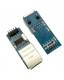
USR-ES1 W5500 chip Új SPI-LAN/Ethernet konverter TCP / IP 51 / STM32 mikrokontroller program W5100 felett
560 Ft 1 166 FtFeatures:
80MHz high-speed SPI interface
Built-in hardware TCPIP protocol stack, users hardly need to master complex network protocol knowledge
Support up to 8 Socket connections
Support TCP, UDP, ICMP, IPv4, ARP, IGMP, PPPoE protocol
Integrated data link layer, physical layer
Support power-down wake-up
Support high-speed serial peripheral interface (SPI mode 0~3)
Internal 32K bytes transmit and receive buffer
Embedded 10BaseT/100BaseTX Ethernet physical layer (PHY)
Support auto-negotiation (10/100-Based full-duplex/half-duplex)
Does not support IP fragmentation
3.3V working voltage, 5V withstand voltage of I/O signal port
LED status display (full-duplex/half-duplex, network connection, network speed, activity status)
Ultra-small pin-type package, convenient for embedded applications
Provide C application examples
Product Features:
Power supply mode: 3.3V external power supply, the current should be greater than 200mA
Control interface form: 3.3V TTL level, SPI interface; 2*single row pin
PCB size (MM): 23 * 25 mm
Mechanical size (length * width * height): 28.5 * 23 * 24 mm
Note: This module is not an SPI-to-Ethernet transparent transmission module, it needs to be used by an external microcontroller, and the user needs to understand how to use the W5500 chip. -
TPA3118 Bluetooth digitális végerősítő 2X30W sztereó módosított Bluetooth hangszóró
545 Ft 1 135 FtTPA3118 Bluetooth Digital Power Amplifier 2X30W Stereo Modified Bluetooth Speaker
Product Description:
Audio input: Bluetooth receiver
Power supply voltage: 8~26VDC (direct current) polarity protection
Power amplifier chip TPA3118 stereo power 2X30W
Applicable speaker impedance: 4, 6, 8 ohm
AUX input: 3.5 headphone jack
After the power is turned on, it will automatically enter the pairing mode. The mobile phone or computer will turn on the Bluetooth search and display the device name: XH-M314 (manufacturers can provide customized device names for batch requirements), click on the pairing to be successful
Product name
Digital Bluetooth power amplifier board
Product number
XH-M314
Chip model
TPA3118
Supply voltage
CD12~28V
Input Current
3Aormore
Output Power
45W*2
Number of channels
Two-channel
Impedance matching
4~8 Ω
Size
71*52*13 mm
weight
33g -
Szín: GY-53 VL53L1X - GY-53 VL53L0X VL53L1X lézeres ToF repülési idő hatótávolság-érzékelő modul soros kimenet
1 029 Ft 2 143 FtGY-53 infrared ranging module (VL53L0X STM32)
Module model: GY-53
Use chip: VL53L0X STM32
Power supply: 3-5v (internal low dropout voltage regulator)
Ranging range: 2 meters (dark light, long distance mode)
Size: 25mm*15.6mm (including mounting holes)
Communication mode: serial port output, PWM output, IIC output of the chip itself.
Pin headers are not soldered by default
Note that since infrared is affected by external light, it will affect the maximum measurement range under strong light and will not affect the measurement accuracy.
Default configuration: serial port baud rate 9600, automatic output, high precision mode.
GY-53-VL53L1X description:
GY-53-VL53L1x is an upgraded version of GY-53 VL53L0X,
It can measure farther, faster, and better anti-interference.
GY-53-VL53L1x Laser ToF Time of Flight Ranging Sensor Module Serial PWM output VL53L1X stm32
It is easy to use, saves complex communication, saves complex algorithms, and directly outputs distance data. It is easier to connect with other single-chip computers and computers (directly use the USB to ttl module to view the distance data on the computer).
GY-53-L1X infrared ranging module (VL53L1X STM32)
Module model: GY-53-L1X
Use chip: VL53L1X STM32
Power supply: 3-5v (internal low dropout voltage regulator)
Ranging range: 5cm-4m (dark light, long distance mode)
Size: 25mm*15.6mm (including mounting holes)
Communication mode: serial port output, PWM output, IIC output of the chip itself.
Provide serial port and pwm to read data codes: stm32, arduino, 51 single-chip microcomputer.
Provide PC display distance software, direct USB to ttl module connection, computer view data.
Pin headers are not soldered by default
Note that since infrared is affected by external light, strong light will affect the maximum measurement range.
Default configuration: serial port baud rate 9600, automatic output, high precision mode. -
Szín: GY-53 VL53L0X - GY-53 VL53L0X VL53L1X lézeres ToF repülési idő hatótávolság-érzékelő modul soros kimenet
525 Ft 1 093 FtGY-53 infrared ranging module (VL53L0X STM32)
Module model: GY-53
Use chip: VL53L0X STM32
Power supply: 3-5v (internal low dropout voltage regulator)
Ranging range: 2 meters (dark light, long distance mode)
Size: 25mm*15.6mm (including mounting holes)
Communication mode: serial port output, PWM output, IIC output of the chip itself.
Pin headers are not soldered by default
Note that since infrared is affected by external light, it will affect the maximum measurement range under strong light and will not affect the measurement accuracy.
Default configuration: serial port baud rate 9600, automatic output, high precision mode.
GY-53-VL53L1X description:
GY-53-VL53L1x is an upgraded version of GY-53 VL53L0X,
It can measure farther, faster, and better anti-interference.
GY-53-VL53L1x Laser ToF Time of Flight Ranging Sensor Module Serial PWM output VL53L1X stm32
It is easy to use, saves complex communication, saves complex algorithms, and directly outputs distance data. It is easier to connect with other single-chip computers and computers (directly use the USB to ttl module to view the distance data on the computer).
GY-53-L1X infrared ranging module (VL53L1X STM32)
Module model: GY-53-L1X
Use chip: VL53L1X STM32
Power supply: 3-5v (internal low dropout voltage regulator)
Ranging range: 5cm-4m (dark light, long distance mode)
Size: 25mm*15.6mm (including mounting holes)
Communication mode: serial port output, PWM output, IIC output of the chip itself.
Provide serial port and pwm to read data codes: stm32, arduino, 51 single-chip microcomputer.
Provide PC display distance software, direct USB to ttl module connection, computer view data.
Pin headers are not soldered by default
Note that since infrared is affected by external light, strong light will affect the maximum measurement range.
Default configuration: serial port baud rate 9600, automatic output, high precision mode. -
GY-63 MS5611 nagy felbontású légköri magasságérzékelő modul IIC / SPI kommunikáció
484 Ft 1 009 FtModule model
GY-63
Name
MS5611 module (atmospheric pressure module)
Use chip
MS5611
Power supply
3~5v (internal low dropout voltage regulator)
Communication method
standard IIC/SPI communication protocol
The chip has a built-in 24bit AD converter, adopts high-quality heavy gold PCB, and the machine welding process guarantees the quality -
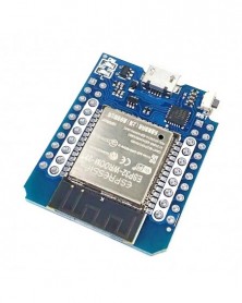
LIVE MINI KIT ESP32 modulfejlesztő kártya WiFi Bluetooth Bluetooth 2 az 1-ben kétmagos CPU
513 Ft 1 068 FtMINI KIT ESP32 module
1. The onboard CP2102 can convert to TTL chip stably to ensure the normal communication of the serial port.
2. Support automatic download, no need to manually switch download and operation mode.
3. Immersion gold craft
4. Support system (cygwin and msys32 simulation environment and development on Linux system)
5. Support ESP32
ESP-WRoom--32 is a general-purpose Wi-Fi T BLE single-chip microcomputer module with powerful functions and a wide range of uses. It can be used for low-power sensor networks and demanding tasks, such as voice encoding, audio streaming, and MP3 decoding Wait.
The core of this module is the ESP32-D0WDQ6 chip, which is scalable and adaptive. The two cpu cores can be independently controlled or powered on. The adjustment range of the clock frequency is from 80MHz to 240MHz. The user can cut off the power of the cpu and use the low-power coprocessor to continuously monitor the status change of the peripherals or whether certain analog quantities exceed the threshold. ESP32 also integrates a wealth of peripherals, including capacitive touch sensors, Hall sensors, low-noise sensor amplifiers, SD card interface, Ethernet interface, high-speed SD10SPI, UART, 12S and 12C, etc.
Cpu and memory
ESP32-D0WDQ6 has built-in two low-power XtensaB332-bitLX66MCUs.
On-chip storage includes: 448KB of ROM, used for program startup and kernel function calls. 520KB on-chip SRAM for data and instruction storage. 8KB of SRAM in RTC, that is, RTC slow memory, can be accessed by the coprocessor in Deep-sleept mode to 8KB of SRAM in RTC,
That is, the RTC fast memory, which can be used for data storage and accessed by the main CPU when the deep sleep mode rtc is started. 1kbit eFuse, of which 256bit is dedicated to the system (MAC address and chip setting); the remaining 768bit is reserved for user applications, which include flash memory encryption and chip ID.
ESP-WR00M-32 integrates 4MB SPIFlash
Download:
https://github.com/MHEtLive/ESP32-MINI-KIT/tree/master/Shield% 20libraries
http://forum.mhetlive.com/category/2/devkit-minikit-testing
https://github.com/MHEtLive/ESP32-MINI-KIT/tree/master/Shield% 20libraries -
W5500 Ethernet hálózati modulok Arduino-hoz TCP/IP 51/STM32 SPI interfész 3.3V 5V I/O MCU Arduino-hoz
540 Ft 1 124 FtWelcome to our Store
If you buy more quantity, Please contact us
Description:
Supports Hardwired TCP/IP Protocols: TCP, UDP, ICMP, IPv4, ARP, IGMP, PPPoE
Supports 8 independent sockets simultaneously
Supports Power-down mode
Supports Wake on LAN over UDP
Supports High-Speed Serial Peripheral Interface(SPI MODE 0, 3)
Internal 32Kbytes Memory for TX/RX Buffers
10BaseT/100BaseTX Ethernet PHY embedded
Supports Auto-Negotiation (Full and half-duplex, 10 and 100-based )
Not supports IP Fragmentation
3.3V operation with 5V I/O signal tolerance
LED outputs (Full/Half duplex, Link, Speed, Active)
48 Pin LQFP Lead-Free Package (7x7mm, 0.5mm pitch)
Specifications:
Chip type: W5500
Supports both 3.3V & 5V.
Hardwired TCP/IP Protocols : TCP, UDP, ICMP, IPv4, ARP, IGMP, PPPoE
10BaseT/100BaseTX Ethernet PHY embedded
Supports automatic response (full-duplex/half-duplex mode)
Supports 8 independent sockets simultaneously
Internal 32Kbytes Memory for Tx/Rx Buffers
Power off mode: support
Network wake: support
SPI interface (SPI MODE 0, 3),convenient connection with MCU
Size: 55mm x 28mm
Color: Blue -
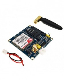
Szín: SIM900 - SIM900A SIM900 V4.0 készlet vezeték nélküli bővítőmodul GSM GPRS kártyaantenna tesztelve az egész
954 Ft 1 987 FtFeatures:
The onboard two-set power supply interface VCC5 5V power supply, VCC4 interface, 3.5--4.5V power supply, optional power on self-starting (default) and control start.
The onboard SMA (default) and IPXmini antenna interface, SIM900A interface reserved reset.
The size of the module is 49*50, all the new and original devices.
The computer can give early computer debugging USB module power supply, a very large amount of data under the condition of the recommended current more than 1A. Standby dozens of MA data can be set to provide dormancy, dormancy of 10MA low power. Support 2, mobile phone 3,4G card.
The serial port circuit: support for 3.3V single-chip microcomputer. TTL serial port support
3.3 and 5V single-chip microcomputer.
The SIM card circuit to increase the SMF05C ESD chip.
Antenna circuit: guarantee short and straight, so as to ensure the signal strength.
PCB display screen printing mark: each interface, convenient development two times, the SIM900/A hardware completely follows the design when the design manual.
Two power supply interfaces: VCC5, 5V DC above 1A. Computer 5V power supply can be early computer USB. DC long data circuit over larger recommended 5V1A. VCC4, 3.5--4.5V power supply, ibid., suitable for a lithium battery.
Control pin all leads.
A TTL level, compatible with 3.3V and 5V.
The two antenna interfaces, the default SMA straight head, connector for IPXmini antenna.
One way of speech interface, the way Mike interface.
The control interface of each pin description:
GND - GND
SIMR SIM900A RDX, TTL level, can not be directly connected to the 232 level
SIMT SIM900A TXD, TTL level, can not be directly connected to the 232 level
RST - SIM900A reset, active low
VCC_MCU when the SIM900A module and 5V TTL level communication, this pin is connected to DC 5V; when the level of communication of SIM900A and 3.3V TTL, this pin is connected to DC 3.3V.
VCC5----DC 5V input.
VCC4------DC3.5--4.5 input
Onboard Resources:
Serial port circuit(with protection)
Antenna interface circuit(SMA bend female port)
SIM card circuit(flip SIM slot)
4*3.5 fixture hole 4pcs
SIM900A serial port output terminal
Specifications:
Size:49mm x 47mm
Net Weight:28g
Weight: 38g
Package Included:
1 x SIM900A V4.0 kit
1x Power Cable
1x Antenna -
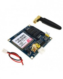
Szín: SIM900A - SIM900A SIM900 V4.0 készlet vezeték nélküli bővítőmodul GSM GPRS kártyaantenna tesztelve az egész
504 Ft 1 049 FtFeatures:
The onboard two-set power supply interface VCC5 5V power supply, VCC4 interface, 3.5--4.5V power supply, optional power on self-starting (default) and control start.
The onboard SMA (default) and IPXmini antenna interface, SIM900A interface reserved reset.
The size of the module is 49*50, all the new and original devices.
The computer can give early computer debugging USB module power supply, a very large amount of data under the condition of the recommended current more than 1A. Standby dozens of MA data can be set to provide dormancy, dormancy of 10MA low power. Support 2, mobile phone 3,4G card.
The serial port circuit: support for 3.3V single-chip microcomputer. TTL serial port support
3.3 and 5V single-chip microcomputer.
The SIM card circuit to increase the SMF05C ESD chip.
Antenna circuit: guarantee short and straight, so as to ensure the signal strength.
PCB display screen printing mark: each interface, convenient development two times, the SIM900/A hardware completely follows the design when the design manual.
Two power supply interfaces: VCC5, 5V DC above 1A. Computer 5V power supply can be early computer USB. DC long data circuit over larger recommended 5V1A. VCC4, 3.5--4.5V power supply, ibid., suitable for a lithium battery.
Control pin all leads.
A TTL level, compatible with 3.3V and 5V.
The two antenna interfaces, the default SMA straight head, connector for IPXmini antenna.
One way of speech interface, the way Mike interface.
The control interface of each pin description:
GND - GND
SIMR SIM900A RDX, TTL level, can not be directly connected to the 232 level
SIMT SIM900A TXD, TTL level, can not be directly connected to the 232 level
RST - SIM900A reset, active low
VCC_MCU when the SIM900A module and 5V TTL level communication, this pin is connected to DC 5V; when the level of communication of SIM900A and 3.3V TTL, this pin is connected to DC 3.3V.
VCC5----DC 5V input.
VCC4------DC3.5--4.5 input
Onboard Resources:
Serial port circuit(with protection)
Antenna interface circuit(SMA bend female port)
SIM card circuit(flip SIM slot)
4*3.5 fixture hole 4pcs
SIM900A serial port output terminal
Specifications:
Size:49mm x 47mm
Net Weight:28g
Weight: 38g
Package Included:
1 x SIM900A V4.0 kit
1x Power Cable
1x Antenna -
TPA3118D2 digitális végerősítő kártya 2.0 kétcsatornás 2*45W audio végerősítő kártya HD XH-M312
486 Ft 1 012 FtProduct parameter
Product Name: Digital Audio Power Amplifier Board
Input voltage: DC 12V-28V (recommended 24V)
Chip type: TPA3118D2*1
Input current: 3A
Input resistance group: 1KΩ
Power supply interface: DC socket (5.5*2.1)
Number of channels: two channels
Magnification: 30TSP
Output power: 45W*2
Output impedance: 4-8 ohms
Appearance size: 66*53MM
Product weight: 40 grams
The chip used in this product has overvoltage protection, overcurrent protection, overheat protection, and short circuit protection
The audio output is a 2P terminal with a spacing of 5MM, which can be connected to a double 30W speaker -
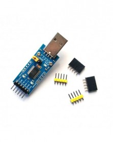
FT232 modul FT232 USB soros port USB TTL FT232R FT232RL frissítés letöltés flash gép
459 Ft 956 FtProduct Features:
Using original FT232RL
Support Mac, Linux, Android, WinCE, Windows 7/8/8.1/10...
Support 3 power supply modes: 5V external power supply; 3.3V external power supply; external power supply (requires 3.3V-5V)
With 3 LEDs: TXD LED, RXD LED, POWER LED
TXD, RXD, RTS#, CTS#: Use curved pin to lead out
Other functional PIN: reserved pad (distribution of headers and sockets, which can be plugged up or down to connect to the user system; the PIN spacing supports the insertion of a universal board)
Instructions for use: (take access to MCU as an example)
VCCIO: output 3.3V or 5V (the module is powered by USB, the jumper cap must be jumped to 3.3V or 5V)
GND: Connect to GND
TXD: Connect to MCU.RX (signal flow: MCU.RX << FT232 << PC.TX)
RXD: connect to MCU.TX (signal flow: MCU.TX >> FT232 >> PC.RX)
RTS: Connect to MCU.CTS (signal flow: MCU.CTS << FT232 << PC.RTS)
CTS: connect to MCU.RTS (signal flow: MCU.RTS >> FT232 >> PC.CTS)
Note: This product does not have a USB cable. The module is USB to TTL level, please do not directly connect to RS232 level, so as not to burn the module. -
ENC28J60 hálózati modul SPI interfész Ethernet mikrokontroller fejlesztőkártya támogatja a modul keskeny testét
408 Ft 851 FtENC28J60 network module SPI Ethernet with network transformer HR911105A interface
Data download address: https://drive.google.com/file/d/1R20PzKC7fTAwjUlwbThpWFWpmbXt839_/view?usp=sharing
1. Onboard ENC28J60/SS chip
2. Onboard 25MHZ crystal oscillator
3. Onboard HR911105A network interface
4. 3.3V pin header power supply
5. PCB size: 48.8(mm)x18.5(mm)
6. SPI interface,
Shipping list:
ENC28J60 network module *1