Kereskedelmi, irodai és ipari
-
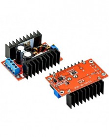
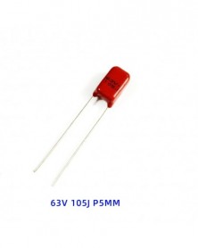
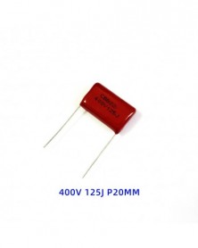
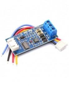
Szín: Boost modul - DC-DC 150W boost modul autós laptop mobil tápegység 10-32V-tól 12-35V-ig állítható
233 Ft 476 FtModule parameters
Module nature: non-isolated boost module
Input mode: IN input positive, IN- input negative
Output mode: OUT output positive, OUT- output negative
Wiring mode: welding-free, terminal
Input voltage: 10-32V
Output voltage: (1) Continuously adjustable (12~35V)
(2) Fixed output (any choice between 12~35V)
Output current: 6A (MAX)
Input current: 10A (MAX) (please increase heat dissipation if it exceeds 10A)
Output power: natural cooling 100W (MAX), plus fan 150W (MAX)
Easily drive 65W 90W laptop including dual core
Use a 12V battery with an ordinary 19V 3.42A notebook computer The temperature of the module is about 45 degrees
Conversion efficiency: 94% (measured at 16V input and 19V 2.5A output) (for reference only)
Working temperature: industrial grade (-40°C to 85°C) (the ambient temperature exceeds 40°C, please reduce the power to use, or add a fan)
Full load temperature rise: 45℃
No-load current: 25mA typical
Short-circuit protection: No, please install an over-current protector at the input
Input reverse connection protection: None, please connect a diode in series with the input
Module weight: 68g
Module size: length 65.4mm* height 24.5mm* (width 56.5mm including heat sink)
Scope of application
1).DIY an output adjustable car power supply, you only need to connect your 12V power supply at the input, you can adjust the output voltage (14-35V) freely and continuously, but the output voltage cannot be lower than the input voltage.
2). Universal car laptop power supply. The input is connected to your 12V power supply, and the output is adjusted to the voltage of your notebook to work.
3). To supply power to your electronic equipment, as long as the voltage is adjusted to the voltage you need and the current does not exceed the rated current, it can work normally.
4). The system front-end power supply, when you are working on a project when the input is 10-18V, and your system board needs a power supply of about 24V and its power is very large, the power of ordinary DC-DC modules is too large. Small, can work directly on the machine without debugging, easily achieve high-efficiency and high-power boost. -
Szín: Réz oszloppal - DC-DC 150W boost modul autós laptop mobil tápegység 10-32V-tól 12-35V-ig állítható
242 Ft 494 FtModule parameters
Module nature: non-isolated boost module
Input mode: IN input positive, IN- input negative
Output mode: OUT output positive, OUT- output negative
Wiring mode: welding-free, terminal
Input voltage: 10-32V
Output voltage: (1) Continuously adjustable (12~35V)
(2) Fixed output (any choice between 12~35V)
Output current: 6A (MAX)
Input current: 10A (MAX) (please increase heat dissipation if it exceeds 10A)
Output power: natural cooling 100W (MAX), plus fan 150W (MAX)
Easily drive 65W 90W laptop including dual core
Use a 12V battery with an ordinary 19V 3.42A notebook computer The temperature of the module is about 45 degrees
Conversion efficiency: 94% (measured at 16V input and 19V 2.5A output) (for reference only)
Working temperature: industrial grade (-40°C to 85°C) (the ambient temperature exceeds 40°C, please reduce the power to use, or add a fan)
Full load temperature rise: 45℃
No-load current: 25mA typical
Short-circuit protection: No, please install an over-current protector at the input
Input reverse connection protection: None, please connect a diode in series with the input
Module weight: 68g
Module size: length 65.4mm* height 24.5mm* (width 56.5mm including heat sink)
Scope of application
1).DIY an output adjustable car power supply, you only need to connect your 12V power supply at the input, you can adjust the output voltage (14-35V) freely and continuously, but the output voltage cannot be lower than the input voltage.
2). Universal car laptop power supply. The input is connected to your 12V power supply, and the output is adjusted to the voltage of your notebook to work.
3). To supply power to your electronic equipment, as long as the voltage is adjusted to the voltage you need and the current does not exceed the rated current, it can work normally.
4). The system front-end power supply, when you are working on a project when the input is 10-18V, and your system board needs a power supply of about 24V and its power is very large, the power of ordinary DC-DC modules is too large. Small, can work directly on the machine without debugging, easily achieve high-efficiency and high-power boost. -
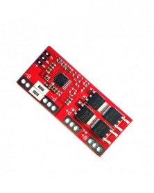
Szín: Enhanced Edition - 3 húr 11,1V 12,6V 18650 lítium akkumulátor védőkártya kiegyenlítéssel és indítható
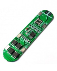
177 Ft 361 Ft3 series 12.6V40A lithium battery protection board
Scope of application: suitable for lithium batteries with a nominal voltage of 3.7V and a full voltage of 4.2V
(Including 18650, 26650, polymer lithium battery, there is no restriction on external dimensions)
Product size: 41*55*3.4mm (enhanced version), 41*60*3.4mm (balanced version)
Product weight: 8.8g (enhanced version), 9.8g (balanced version)
Charging voltage: 12.6V~13.6V
Continuous discharge current (upper limit): 40A (If the heat dissipation environment is not good, please reduce the load current to use)
Continuous charging current (upper limit): 20A
Enhanced version: suitable for electric drills with starting current below 80A and power below 170W.
Balanced version: suitable for electric drills with starting current below 80A and power below 170, with equalizing charging function.
Note 1: Successful start of the electric drill requires 3 10C-20C power batteries, or 6 5C-10C power batteries (recommended power battery models: SONY VTC4, VTC4A, VTC5A, VTC6), 0V and 12.6V connection lines, use Wires of more than 3 square millimeters (Nickel sheets cannot be used!).
Note 2: Wiring 0V, 4.2V, 8.4V, 12.6V strictly according to the diagram, and do not touch any components on the board when welding the wire, and do not intentionally short-circuit.
Note 3: When the battery is being welded for the first time or is being charged, as long as a single battery exceeds 4.2V, the "430" resistor will heat up and discharge (discharge to about 4.19V to stop heating). If the "430" resistor is seriously hot (you can't touch it when it is too hot), please check whether it is connected to the wrong wire.
Conditions for successfully starting the electric drill:
1. Need 3 15C-20C power batteries or 6 10C-15C power batteries. (Ordinary 18650 can't start the electric drill!!)
2, 0V and 12.6V connection wires , use copper wires of more than 3 square millimeters, the shorter the length, the better.
3S40A electrical parameters
Project
Minimum
Typical value
Max
Unit
Remarks
Self-consumption
current
12
18
24
uA
Overcharge
protection voltage
4.2
4.25
4.3
V
Balanced starting
voltage
4.17
4.2
4.23
V
Balanced version
Balance current
95
100
105
mA
Balanced version
Balance heating
power
1.17
1.29
1.43
W
Balanced version
Overcharge
recovery voltage
4.1
4.15
4.2
V
Over-discharge
protection voltage
2.4
2.5
2.6
V
Voltage recovery
after over-discharge protection
2.8
3
3.2
V
1C discharge
Voltage recovery
after over-discharge protection
3.2
3.5
3.8
V
2C discharge
Overdischarge
recovery voltage
2.9
3.2
3.3
V
Turn-on internal
resistance
2.5
3
3.5
mΩ
Overcurrent
protection current
70
80
90
A
Overcurrent delay
time
100
150
200
ms
Continuous working
current
0
40
40
A
Blocking load
Continuous output
power
0
504
504
W
Blocking load
Ambient
temperature
-40
25
85
°C -
Szín: Kiegyensúlyozott változat - 3 húr 11,1V 12,6V 18650 lítium akkumulátor védőkártya kiegyenlítéssel és
185 Ft 377 Ft3 series 12.6V40A lithium battery protection board
Scope of application: suitable for lithium batteries with a nominal voltage of 3.7V and a full voltage of 4.2V
(Including 18650, 26650, polymer lithium battery, there is no restriction on external dimensions)
Product size: 41*55*3.4mm (enhanced version), 41*60*3.4mm (balanced version)
Product weight: 8.8g (enhanced version), 9.8g (balanced version)
Charging voltage: 12.6V~13.6V
Continuous discharge current (upper limit): 40A (If the heat dissipation environment is not good, please reduce the load current to use)
Continuous charging current (upper limit): 20A
Enhanced version: suitable for electric drills with starting current below 80A and power below 170W.
Balanced version: suitable for electric drills with starting current below 80A and power below 170, with equalizing charging function.
Note 1: Successful start of the electric drill requires 3 10C-20C power batteries, or 6 5C-10C power batteries (recommended power battery models: SONY VTC4, VTC4A, VTC5A, VTC6), 0V and 12.6V connection lines, use Wires of more than 3 square millimeters (Nickel sheets cannot be used!).
Note 2: Wiring 0V, 4.2V, 8.4V, 12.6V strictly according to the diagram, and do not touch any components on the board when welding the wire, and do not intentionally short-circuit.
Note 3: When the battery is being welded for the first time or is being charged, as long as a single battery exceeds 4.2V, the "430" resistor will heat up and discharge (discharge to about 4.19V to stop heating). If the "430" resistor is seriously hot (you can't touch it when it is too hot), please check whether it is connected to the wrong wire.
Conditions for successfully starting the electric drill:
1. Need 3 15C-20C power batteries or 6 10C-15C power batteries. (Ordinary 18650 can't start the electric drill!!)
2, 0V and 12.6V connection wires , use copper wires of more than 3 square millimeters, the shorter the length, the better.
3S40A electrical parameters
Project
Minimum
Typical value
Max
Unit
Remarks
Self-consumption
current
12
18
24
uA
Overcharge
protection voltage
4.2
4.25
4.3
V
Balanced starting
voltage
4.17
4.2
4.23
V
Balanced version
Balance current
95
100
105
mA
Balanced version
Balance heating
power
1.17
1.29
1.43
W
Balanced version
Overcharge
recovery voltage
4.1
4.15
4.2
V
Over-discharge
protection voltage
2.4
2.5
2.6
V
Voltage recovery
after over-discharge protection
2.8
3
3.2
V
1C discharge
Voltage recovery
after over-discharge protection
3.2
3.5
3.8
V
2C discharge
Overdischarge
recovery voltage
2.9
3.2
3.3
V
Turn-on internal
resistance
2.5
3
3.5
mΩ
Overcurrent
protection current
70
80
90
A
Overcurrent delay
time
100
150
200
ms
Continuous working
current
0
40
40
A
Blocking load
Continuous output
power
0
504
504
W
Blocking load
Ambient
temperature
-40
25
85
°C -
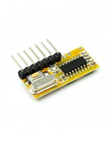
Szín: tábla - ESP8266 ESP-01/01S 5V WiFi relé modul Dolgok Smart Home távirányító kapcsoló telefon APP ESP01 ESP-01
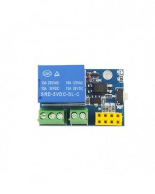
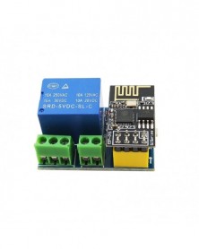
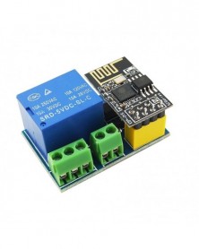
161 Ft 329 FtThis WIFI relay based on ESP-01 or ESP-01S WIFI module. It is designed for smart home, Internet of thing and other DIY project. With this smart relay, you will easy to DIY your smart switch to control any device by your phone anywhere.
Product parameters:
Product size: 37 * 25mm
Operating voltage: DC5V
Communication: WIFI (ESP8266 module)
Transmission distance: the maximum transmission distance of 400m (open environment, mobile phone equipped with WIFI module)
Load: 10A/250VAC 10A/30VDC, the relay pull 100,000 times
Package Included:
1 x ESP8266 5V WiFi relay module Things smart home remote control switch phone APP ESP-01S relay module -
Szín: ESP01-es tábla - ESP8266 ESP-01/01S 5V WiFi relé modul Dolgok Smart Home Távirányító Kapcsoló Telefon APP ESP01
247 Ft 505 FtThis WIFI relay based on ESP-01 or ESP-01S WIFI module. It is designed for smart home, Internet of thing and other DIY project. With this smart relay, you will easy to DIY your smart switch to control any device by your phone anywhere.
Product parameters:
Product size: 37 * 25mm
Operating voltage: DC5V
Communication: WIFI (ESP8266 module)
Transmission distance: the maximum transmission distance of 400m (open environment, mobile phone equipped with WIFI module)
Load: 10A/250VAC 10A/30VDC, the relay pull 100,000 times
Package Included:
1 x ESP8266 5V WiFi relay module Things smart home remote control switch phone APP ESP-01S relay module -
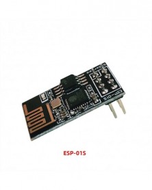
Szín: ESP-01 - ESP8266 ESP-01/01S 5V WiFi relé modul Dolgok Smart Home Távirányító Kapcsoló Telefon APP ESP01 ESP-01
170 Ft 347 FtThis WIFI relay based on ESP-01 or ESP-01S WIFI module. It is designed for smart home, Internet of thing and other DIY project. With this smart relay, you will easy to DIY your smart switch to control any device by your phone anywhere.
Product parameters:
Product size: 37 * 25mm
Operating voltage: DC5V
Communication: WIFI (ESP8266 module)
Transmission distance: the maximum transmission distance of 400m (open environment, mobile phone equipped with WIFI module)
Load: 10A/250VAC 10A/30VDC, the relay pull 100,000 times
Package Included:
1 x ESP8266 5V WiFi relay module Things smart home remote control switch phone APP ESP-01S relay module -
Szín: ESP-01S - ESP8266 ESP-01/01S 5V WiFi relé modul Dolgok Smart Home távirányító kapcsoló telefon APP ESP01 ESP-01
170 Ft 347 FtThis WIFI relay based on ESP-01 or ESP-01S WIFI module. It is designed for smart home, Internet of thing and other DIY project. With this smart relay, you will easy to DIY your smart switch to control any device by your phone anywhere.
Product parameters:
Product size: 37 * 25mm
Operating voltage: DC5V
Communication: WIFI (ESP8266 module)
Transmission distance: the maximum transmission distance of 400m (open environment, mobile phone equipped with WIFI module)
Load: 10A/250VAC 10A/30VDC, the relay pull 100,000 times
Package Included:
1 x ESP8266 5V WiFi relay module Things smart home remote control switch phone APP ESP-01S relay module -
RFID modul RC522 mini Kits S50 13,56 Mhz 6cm címkékkel SPI Write & Read for arduino uno 2560
165 Ft 337 Ft[Introduction to RC522 chip]
MF RC522 is a highly integrated card reader/writer chip used in 13.56MHz contactless communication. It is a low-voltage, low-cost, and small non-contact card reader/writer chip for the "three-meter" application. It is a smart meter And a better choice for the development of portable handheld devices. MF RC522 utilizes advanced modulation and demodulation concepts and fully integrates all types of passive non-contact communication methods and protocols under 13.56MHz. Support 14443A compatible transponder signal. The digital part handles ISO14443A frames and error detection. In addition, it also supports the fast CRYPTO1 encryption algorithm to verify the MIFARE series of products. MFRC522 supports the higher-speed non-contact communication of the MIFARE series, with a two-way data transmission rate of up to 424kbit/s. As a new member of the 13.56MHz high-integration card reader/writer series chip family, MF RC522 has many similarities with MF RC500 and MF RC530 but also has many features and differences. The communication between it and the host adopts SPI mode, which is conducive to reducing the connection, reducing the size of the PCB board and reducing the cost.
[Introduction to RFID Module]
The MF522-MINI module adopts the RC522 chip to design the card reading circuit. The module works at 13.56MHz frequency, conforms to the ISO14443A standard, and can support Mifare1 S50, Mifare1 S70, Mifare Light, Mifare UltraLight, and Mifare Pro. It is suitable for users of advanced applications such as equipment development and card reader development, and users who need to design/produce radio frequency card terminals. This module can be directly loaded into various card reader molds. The module uses a voltage of 3.3V, and can directly connect to any user's CPU motherboard through a few simple lines of the SPI interface, which can ensure the stable and reliable work of the module and the long distance of the card; the module is easy to use, highly reliable, and small in size. And other features can help customers to conveniently and quickly apply contactless cards to the system.
[Introduction to electrical parameters]
Working current: 13—26mA/DC 3.3V
Idle current: 10-13mA/DC 3.3V
Sleep current: <80uA
Peak current: <30mA
Working frequency: 13.56MHz
Supported card types: mifare1 S50, mifare1 S70, mifare UltraLight, mifare Pro, mifare Desfire
Product physical characteristics: size: 37.5mm×33mm
Environmental working temperature: -20—80 degrees Celsius
Environmental storage temperature: -40-85 degrees Celsius
Environmental relative humidity: relative humidity 5% -95%
【Shipping list】
1. One RC522 MINI module;
2. A standard S50 blank card;
3. One S50 special-shaped card (the shape of the keychain as shown in the picture);
4. One straight row and one curved row pin; -
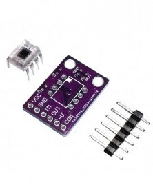
OPT101 megvilágítás érzékelő fényintenzitás érzékelő modul monolitikus fotodióda
171 Ft 348 FtProduct Description:
OPT101 is a monolithic photodiode with an on-chip transimpedance amplifier. The combination of photodiodes and transimpedance amplifiers on a single chip eliminates problems often encountered in discrete designs, such as leakage current errors, noise pickup, and gain peaking as a result of stray capacitance. The output voltage increases linearly with the light intensity. The amplifier is designed for single-supply or dual-supply operation.
Product features:
1. Single power supply: 2.7-36V
2. Photodiode size: 2.29mm * 2.29mm
3. Internal 1Mohm feedback resistor
4. High response: 0.45A/W (650nm)
5. Width: 14Khz
6. Low peak current: 120UA
7. Packaging: Clear plastic 8-pin PDIP and J-lead SOP
Applications:
1. Medical Instruments
2. Experimental equipment
3. Position and proximity sensor
4. Photographic analyzer
5. Barcode scanner
6. Detector
7. Currency Exchange -
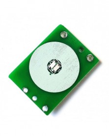
1 db 12 V-os kapacitív érintéskapcsoló gombmodul behúzható retesz TTp223 relé modullal
173 Ft 354 FtMost customers use this module to refit automobiles and motorcycles, LED lights and light belts, mirror-touch, and all kinds of equipment that need to be loaded directly, etc.
Touch module can be set to move or lock, sensitivity can be adjusted (no welding capacitance, zero degrees is the highest. Default delivery), also can lead out touch.
Indicator light: no output of the power-on blue light, and output when touching the red light; Output equals input.
Input/Output DC:6v-20v (note: stable voltage power supply is supported, and constant current power supply is not supported temporarily)
Driving Current: 3A standby consumption: 6MA circuit board size: 24mm * 32mm * 1.6mm
At present, the cooperative customers are mostly used to research and develop touch switches, LEDlampretrofit, car modification, escape the room game, various large machinery products, and equipment, etc.
It can be widely used in lighting control, toys, household appliances, kitchens, bathroom mirrors, and other products. -
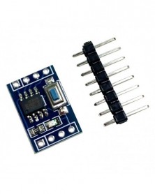
Szín: STC15F104W - STC15F104W STC15W204S egychipes mikroszámítógép modul alaplap alaplap oktatókártya fejlesztő kártya
171 Ft 348 FtThe difference between STC15F104E and STC15F104W:
1. The external interrupt of STC15F104E is not easy to use, the external interrupt of STC15F104W can be used, and there is one more dedicated timer for wake-up after power failure.
2. The timers of STC15F104E have T0 and T1, while the timers of STC15F104W are T0 and T2.
3. The pins are different.
STC15F104W highlights:
(1) Timer module: T0 and T2. When T0 works in mode 0, it is a 16-bit timer counter that can automatically reload the initial value, when mode 2 is an 8-bit counter that automatically reloads, and mode 3 is decomposable; The working mode of T2 is fixed at the 16-bit auto-reloading initial value mode, so it is especially suitable for the LED industry. The timer module of this chip can produce more precise timing time.
(2) Kernel: It adopts Y5 ultra-high-speed CPU kernel, which is 20% faster than ordinary 1T. See the instruction set for details. A total of 111 instructions.
(3) Pin diagram:
P3.3 is RSTOUT_LOW, it outputs low level after power-on and reset. It can also be set to low or high level by software. This pin can be used as the reset circuit of 16-bit or 32-bit single-chip microcomputer; P3.4 can output the system clock, Therefore, it can be used as the clock circuit of 16-bit or 32-bit single-chip microcomputer; the chip also has a strong encryption function, which can replace the encryption chip, and the unit price is only one piece, so it can be recommended to customers.
STC15F104W has no serial port, and has a relay broadcast mode. It can simulate I2C, serial port, SPI by software, and use IO port to charge and discharge to measure external voltage to achieve AD function.
The input level of P3.1 direct output P3.0 can be set in the download software, similar to the relay broadcast mode of 15 series serial port 1.
The detailed description is as follows:
1 All IO ports are all led out
2 Onboard a single-chip controlled LED, connected to IO port P3.2, can be used for IO port output, PWM wave modulation and other experiments
3 Onboard a patch switch, connected to IO port P3.3, can be used for IO port input, interrupt and other experiments
4 The patch switch and LED external to the IO port do not affect the normal use of the IO port
5 Onboard TTL level serial port, RXD (connected to P3.0) and TXD (connected to P3.1) can be used for STC download program/serial port upper and lower computer communication (requires timer cooperation) and IO port input and output experiments
6 Attached test program -
Szín: STC15W204S - STC15F104W STC15W204S egychipes mikroszámítógép modul alaplap alaplap oktatókártya fejlesztő kártya
171 Ft 348 FtThe difference between STC15F104E and STC15F104W:
1. The external interrupt of STC15F104E is not easy to use, the external interrupt of STC15F104W can be used, and there is one more dedicated timer for wake-up after power failure.
2. The timers of STC15F104E have T0 and T1, while the timers of STC15F104W are T0 and T2.
3. The pins are different.
STC15F104W highlights:
(1) Timer module: T0 and T2. When T0 works in mode 0, it is a 16-bit timer counter that can automatically reload the initial value, when mode 2 is an 8-bit counter that automatically reloads, and mode 3 is decomposable; The working mode of T2 is fixed at the 16-bit auto-reloading initial value mode, so it is especially suitable for the LED industry. The timer module of this chip can produce more precise timing time.
(2) Kernel: It adopts Y5 ultra-high-speed CPU kernel, which is 20% faster than ordinary 1T. See the instruction set for details. A total of 111 instructions.
(3) Pin diagram:
P3.3 is RSTOUT_LOW, it outputs low level after power-on and reset. It can also be set to low or high level by software. This pin can be used as the reset circuit of 16-bit or 32-bit single-chip microcomputer; P3.4 can output the system clock, Therefore, it can be used as the clock circuit of 16-bit or 32-bit single-chip microcomputer; the chip also has a strong encryption function, which can replace the encryption chip, and the unit price is only one piece, so it can be recommended to customers.
STC15F104W has no serial port, and has a relay broadcast mode. It can simulate I2C, serial port, SPI by software, and use IO port to charge and discharge to measure external voltage to achieve AD function.
The input level of P3.1 direct output P3.0 can be set in the download software, similar to the relay broadcast mode of 15 series serial port 1.
The detailed description is as follows:
1 All IO ports are all led out
2 Onboard a single-chip controlled LED, connected to IO port P3.2, can be used for IO port output, PWM wave modulation and other experiments
3 Onboard a patch switch, connected to IO port P3.3, can be used for IO port input, interrupt and other experiments
4 The patch switch and LED external to the IO port do not affect the normal use of the IO port
5 Onboard TTL level serial port, RXD (connected to P3.0) and TXD (connected to P3.1) can be used for STC download program/serial port upper and lower computer communication (requires timer cooperation) and IO port input and output experiments
6 Attached test program -
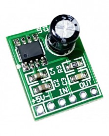
XPT8871 mini teljesítményerősítő kártya 5 V mono teljesítményű audio erősítő modul diy mini hangszóró
94 Ft 191 FtProduct name: 5V sound single channel power amplifier board
Product specifications: 20*16*8mm
Power supply voltage: 5V, 1A (Positive and negative can not be reversed, if the reverse is connected, burn the IC immediately)
Output power: 5W
Notice! This board needs to be welded, friends with tools, and friends with a certain amount of hands-on ability can play it. -
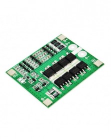
3 sorozatú 12V18650 lítium akkumulátorvédő kártya 11,1V 12,6V, kiegyensúlyozott 25A túláram-, túltöltés- és
167 Ft 341 FtNote: This protection board cannot be used for lithium iron phosphate batteries, hernia lights, hand drill battery packs, electric fish machine battery packs, electric bicycle battery packs, children's car batteries, motors above 775 (4A), and 1W fisheye LEDs. Lamps, please pay attention to customers who purchase the above combination! .
The power range described is applicable to the following products:
Massager battery pack, LED lamp backup power supply, 12V electronic products, solar street lamp battery pack, monitoring backup power supply, and other products.
Note: For products with a current above 3A, the battery discharge rate must be above 3C.
The magnification calculation formula: for a battery with a 1C magnification, the capacity of 2000 is equal to 2AH*1=2A working current.
3C rate battery, 2000 capacity is equal to 2AH*3=6A working current.
In use, the battery will heat up, which means that the battery rate is not applicable. In this case, the battery cannot be used for a long time, and the battery will be damaged quickly.
Note 1: Wiring 0V (B-), 3.7V (B1), 7.4V (B2), 11.1V (B ) strictly according to the diagram, do not intentionally short-circuit!
Note 2: After the line is connected, it needs to be charged before output.
Note 3: When connecting 3 sets of batteries in series, please ensure that the voltage of each set of batteries is the same. If they are not the same, please charge each set of batteries separately and use them in series. During the discharge test, the battery with the fastest voltage drop is the poor battery.
Explain: Do not mix good batteries and bad batteries together! The closer the capacity/internal resistance of the 3 sets of batteries, the better! (2 good batteries 1 bad battery use effect = 3 bad batteries use effect).
Properties of lithium battery protection board
Model
HX-3S-FL25A-A
Internal resistance
<100 mΩ
Overcharge voltage range
4.25~4.35V(±0.05V)
Operating temperature
-40℃~ 50℃
Over-discharge voltage range
2.3~3.0V(±0.05V)
Storage conditions
-40℃~ 80℃
Working current
0-25A
Effective life
>30000Hours
Instantaneous current
35~40A
Short circuit protection
Can be protected ,delayed self-recovery.
Quiescent Current
<30uA
size
56*45*4.0 mm -
DHT11 digitális hőmérséklet- és páratartalom-érzékelő modul, hőmérséklet-modul páratartalom-modul
166 Ft 338 Ft1. Product overview
DHT11 Humidity Capacitor Digital Temperature and Humidity Module is a temperature and humidity composite sensor with calibrated digital signal output. It uses dedicated digital module acquisition technology and temperature and humidity sensing technology to ensure that the product has extremely high reliability and excellent long-term stability. The sensor includes a capacitive humidity sensing element and a high-precision temperature measuring element, and is connected with a high-performance 8-bit single-chip microcomputer. Therefore, the product has the advantages of excellent quality, ultra-fast response, strong anti-interference ability, and high cost performance. Each sensor is calibrated in an extremely accurate humidity calibration room. The calibration coefficients are stored in the single-chip microcomputer in the form of a program, and these calibration coefficients must be called during the processing of the detection signal inside the sensor. Standard single bus interface makes system integration easy and quick. Ultra-small size, extremely low power consumption, and signal transmission distance of up to 20 meters or more, making it a good choice for various applications and even for demanding applications. The product is 3-lead (single bus interface) for easy connection. Special packaging forms can be provided according to user needs.
Second, the scope of application
HVAC, dehumidifiers, testing and inspection equipment, consumer products, automobiles, automatic controls, data loggers, home appliances, humidity regulators, medical care, weather stations, and other related humidity detection and control.
3. Product highlights
Ultra-low energy consumption, long transmission distance, full automatic calibration, use of capacitive humidity sensor, complete interchangeability, standard digital single bus output, excellent long-term stability, use of high-precision temperature measurement components.
Four, product parameters
Size: 40*23mm
Weight: 4g
Voltage: 5V
Port: digital bidirectional single bus
Temperature range: 0---50℃ ±2℃
Humidity range: 20---90% RH ±2% RH -
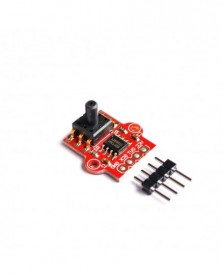
Szín: 1 db - Nyomásérzékelő Levegőnyomás-érzékelő modul Vízszint-érzékelő modul
168 Ft 343 FtFeatures:
This air pressure module adopts high-precision AD sampling chip, adopts a 0-40KPa air pressure sensor, can be connected to a 2.5mm hose, can detect the water level and other air pressure, the voltage is 3.3V-5V, the volume is small, and the 5k resistor bridge is used on it. The specific pressure value needs to be calculated by yourself. We can't provide other information. After reading the above description, we are shooting.
Size: 19*18mm (2mm fixing hole)
Voltage: 3.3V~5V
Pressure: 0~40KPa -
1 db GY-MAX4466 elektret mikrofonerősítő modul MAX4466, állítható erősítés Arduinohoz
162 Ft 330 FtDescription
The MAX4466 is a micropower operational amplifier optimized for use as a microphone preamplifier. They offer an ideal combination of optimized gain-bandwidth products and supply current, as well as low-voltage operation in ultra-small packages. The MAX4466 has gain stability and provides a gain bandwidth of 200kHz with only 24uA of supply current. After decompression, a minimum stable gain of 5V/ V is achieved and a 600kHz gain-bandwidth product is provided. In addition, these amplifiers feature rail-to-rail output, high AVOL, and excellent power supply rejection, and common-mode rejection ratios for operation in noisy environments. Widely used in cellular phones digital repeaters, headphones, hearing aids, microphone preamps, portable computers, speech recognition systems, etc.
Features and benefits:
Power supply voltage: 2.4vto 5.5v(can be directly connected to STM/ARDUNIO Raspberry Pi and other development board)
Power supply rejection ratio: 112dB
Common mode rejection ratio: 126dB
Avol:125db(rl=100k2)rail-to-rail- output
Static supply current: <24uA
Gain Bandwidth: 600kHz
Size: 20.8MM*13. 8MM*7. 5MM
Application:
Cellular phone
Digital repeater
Headphones
Hearing aids
Microphone preamplifier
Portable computer
Speech recognition system -
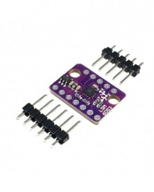
GY-LSM6DS3 modul 6 Degrees of Freedom Breakout IIC/SPI átvitel
165 Ft 337 FtDescription: The
LSM6DS3 is a accelerometer and gyroscope sensor with a giant 8kb FIFO
buffer and embedded processing interrupt functions, specifically
targeted at the cellphone market. Due to the capabilities and low cost
of the LSM6DS3 we’ve created this small breakout board just for you!
Each LSM6DS3 Breakout has been designed to be super-flexible and can be
configured specifically for many applications. With the LSM6DS3 Breakout
you will be able to detect shocks, tilt, motion, taps, count steps, and
even read the temperature!
The
LSM6DS3 is capable of reading accelerometer data up to 6.7kS/s and
gyroscope data up to 1.7kS/s for more accurate movement sensing. As
stated before this breakout also has the ability to buffer up to 8kB of
data between reads, host other sensors, and drive interrupt pins all
thanks to the LSM6DS3’s built-in FIFO.
Each pin has been broken out on the LSM6DS3, with one side of the board featuring power and I2C
functionality while the other side sporting pins that control SPI
functionality and interrupt outputs. Please keep in mind that the
LSM6DS3 is a 3.3V device so supplying voltages greater than ~3.6V can
permanently damage the IC. A logic level shifter is required for any
development platform operating at 5V.
Features:
Power consumption: 0.9 mA in combo normal mode and 1.25 mA in combo high-performance mode up to 1.6 kHz.
“Always on” experience with low power consumption for both accelerometer and gyroscope
Smart FIFO up to 8 kbyte based on features set
±2/±4/±8/±16 g full scale
±125/±245/±500/±1000/±2000 dps full scale
Analog supply voltage: 1.71 V to 5 V
SPI/I2C serial interface with main processor data synchronization feature
Embedded temperature sensor
Size: 13mm*18mm -
6 sorozatú lítium akkumulátor védő kártya 22,2V/25,2V 18650 akkumulátor egyensúly védőkártya 14A árammal
171 Ft 348 FtThis protection board cannot be used for lithium iron phosphate batteries, hernia lights, hand drill battery packs, electric fish machine battery packs, electric bicycle battery packs, children's car batteries, power motors above 550, and 1W fisheye LED lights for the above combination Please pay attention to customers who purchase!
The power range described is applicable to the following products:
Massager battery pack, LED lamp backup power supply, 12V electronic products, solar street lamp battery pack, monitoring backup power supply, and other products.
Product parameters:
Size: 34*53. 5*3 mm
Online working current: 14A (pay attention to heat dissipation)
Upper limit instantaneous current: 20A
Balance current: 56mA
Overcharge voltage range: 4.25V±0.05V
Over-discharge voltage range: 2. 7V±0.05V
Quiescent current: less than 30uA
Charging voltage: 25.2V~26V
Short circuit protection: can protect, delay self-recovery -
4 sorozatú 14,8V 18650 lítium-polimer akkumulátorvédő kártya 16,8V túltöltés és túlkisülés elleni 12A áramkorlát
158 Ft 322 FtNote: The lithium battery protection board cannot be used for lithium iron phosphate batteries, hernia lights, hand drill battery packs, electric fish machine battery packs, electric bicycle battery packs, children's car batteries, power motors above 550, and 1W fish eye LEDs. Lamps, please pay attention to customers who purchase the above combination!
The power range described is applicable to the following products:
Massager battery pack, LED lamp backup power supply, 12V electronic products, solar streetlamp battery pack, monitoring backup power supply, and other products.
Note: For products with a current above 3A, the battery discharge rate must be above 3C.
The magnification calculation formula: for a battery with a 1C magnification, the capacity of 2000 is equal to 2AH*1=2A working current.
3C rate battery, 2000 capacity is equal to 2AH*3=6A working current.
The battery will heat up during use, which means that the battery rate is not applicable. In this case, the battery cannot be used for a long time and the battery will be damaged quickly.
Note 1: Wiring 0V (B-), 3.7V (B1), 7.4V (B2), 11.1V (B ) strictly according to the diagram, do not intentionally short-circuit!
Note 2: After the line is connected, it needs to be charged before output.
Note 3: When connecting 4 sets of batteries in series, please ensure that the voltage of each set of batteries is the same. If they are not the same, please charge each set of batteries separately and then use them in series. During the discharge test, the battery with the fastest voltage drop is the poor battery.
Explain: Do not mix good batteries and bad batteries together! The closer the capacity/internal resistance of the 4 sets of batteries are, the better! (2 good batteries 2 bad batteries = 4 bad batteries).
Properties of the protection board:
Model: Long HX-4S-A01/Short HX-4S-A10
Short size: 65*17*3.0mm
Long section size: 72*17*3.0mm
Overcharge voltage range: 4.25~4.35V(±0.5V) Overdischarge voltage range: 2.3-3.0V(±0.5V)
Charging voltage: 16.8V~17V
Maximum operating current: 6~8A
Upper limit instantaneous current: 12A
Quiescent current: less than 30uA
Internal resistance: less than 100mΩ
Working temperature: -40~ 50℃
Storage conditions: -40~ 80℃
Effective life: more than 50000 hours
Short circuit protection: it can be protected and needs to be recharged
Protection board device description: The components are S-8254AA protection chip and AO4407*4. -
Szín: GY-302 - GY-302 GY-30 BH1750 BH1750FVI A BH1750FVI digitális optikai fényerősség-érzékelő az arduino 3V~5V
153 Ft 312 FtGY-30 GY-302Light sensor module
BH1750VI module digital light intensity
1. Roh-bh1750fvi chip is adopted
2. Power supply: 3-5V
3. Luminance range: 0-65535 LX
4. The sensor built-in 16bitAD converter
5. Direct digital output, omit complex calculation, omit calibration
6. No distinction between environmental light sources and spectroscopic properties close to visual sensitivity
7. High precision determination of 1 lux for a wide range of luminance 8. Standard NXPlIc communication protocol
9. The module contains communication level conversion and is directly connected to 5V SINGLE-chip
10. Provide STC51 C language test code, C8051F340 C language test code, AVRM16 C language test code
1. Model Number: GY-302
2.Size:13.9mm*18.5mm
3. ROHM original BH1750FVI chip is adopted
4. Power supply: 3-5V
5. Data range: 0-65535
6. The sensor built-in 16bitAD converter
7. Direct digital output, omit complex calculation omit calibration 8. Do not distinguish between environmental light sources
9. Spectral characteristics close to visual sensitivity
High precision determination of 1 lux for a wide range of luminance 11. Provide STC51 test code, C8051F340 test code, AVRM16 test code and Arduino test code -
Szín: GY-30 - GY-302 GY-30 BH1750 BH1750FVI A BH1750FVI digitális optikai fényerősség-érzékelő az arduino 3V~5V modulhoz
162 Ft 330 FtGY-30 GY-302Light sensor module
BH1750VI module digital light intensity
1. Roh-bh1750fvi chip is adopted
2. Power supply: 3-5V
3. Luminance range: 0-65535 LX
4. The sensor built-in 16bitAD converter
5. Direct digital output, omit complex calculation, omit calibration
6. No distinction between environmental light sources and spectroscopic properties close to visual sensitivity
7. High precision determination of 1 lux for a wide range of luminance 8. Standard NXPlIc communication protocol
9. The module contains communication level conversion and is directly connected to 5V SINGLE-chip
10. Provide STC51 C language test code, C8051F340 C language test code, AVRM16 C language test code
1. Model Number: GY-302
2.Size:13.9mm*18.5mm
3. ROHM original BH1750FVI chip is adopted
4. Power supply: 3-5V
5. Data range: 0-65535
6. The sensor built-in 16bitAD converter
7. Direct digital output, omit complex calculation omit calibration 8. Do not distinguish between environmental light sources
9. Spectral characteristics close to visual sensitivity
High precision determination of 1 lux for a wide range of luminance 11. Provide STC51 test code, C8051F340 test code, AVRM16 test code and Arduino test code -
4 szál lítium akkumulátor védőkártya 30A nagy áramerősség 4 húr aktiválás nélkül, automatikus helyreállítás
158 Ft 322 Ft4 series lithium battery protection boards, suitable for nominal voltage 14.4V lithium battery pack, 14.8V lithium battery pack, 16.8V lithium battery pack. With automatic activation function, the protection is automatically cancelled after the protection condition is restored, without the need for charger activation, which is more convenient to use.
Module parameters:
Module name: 4-string lithium battery protection board
Module nature: polymer lithium battery protection board
Overcharge detection voltage: 4.25±0.025V
Overcharge release voltage: 4.15±0.05V
Overdischarge detection voltage: 2.50±0.08V
Over-discharge release voltage: 3.00±0.1V
Overcurrent current: 20-30A
Working current: 15A (natural heat dissipation 10A, plus heat sink 15A, maximum instantaneous current 30A)
Release conditions: the protection conditions are released and automatically restored without activation (optional charger activation)
Main functions: overcharge protection, overdischarge protection, short circuit protection, overcurrent protection.
Working temperature: -40~ 85 degrees (please strengthen heat dissipation when the ambient temperature is too high)
Wiring mode: welding output
Module size: 50mm*22mm*4mm
Application range:
This protection board can be used as a nominal voltage of 14.4V, 14.8V, 16.8V four-string polymer lithium battery pack, four-string 18650 lithium battery pack, etc. for overcharge, overdischarge, short circuit protection, etc. The function without activation is used in power applications with high instantaneous currents. In inverter applications, false triggering protection can be avoided, making it more convenient to use. -
5 szál 18,5V18650 lítium akkumulátorvédő kártya a túltöltés és a túlkisülés megelőzése érdekében 21 V napelemes
153 Ft 312 FtNote: The lithium battery protection board cannot be used for lithium iron phosphate batteries, hernia lights, hand drill battery packs, electric fish machine battery packs, electric bicycle battery packs, children's car batteries, power motors above 550, and 1W fisheye LEDs. Lamps, please pay attention to customers who purchase the above combination! .
The power range described is applicable to the following products:
Massager battery pack, LED lamp backup power supply, 12V electronic products, solar street lamp battery pack, monitoring backup power supply, and other products.
Note: For products with a current above 3A, the battery discharge rate must be above 3C.
The magnification calculation formula: for a battery with a 1C magnification, the capacity of 2000 is equal to 2AH*1=2A working current.
3C rate battery, 2000 capacity is equal to 2AH*3=6A working current.
In use, the battery will heat up, which means that the battery rate is not applicable. In this case, the battery cannot be used for a long time, and the battery will be damaged quickly.
Note 1: Wiring 0V(B-), 3.7V(B1), 7.4V(B2), 11.1V(B3), 14.8V(B4), 18.5V(B ) strictly according to the diagram, don't short-circuit intentionally!
Note 2: After the line is connected, it needs to be charged before output.
Note 3: When connecting 5 groups of batteries in series, please ensure that the voltage of each group of batteries is the same. If they are not the same, please charge each group of batteries separately and then use them in series. During the discharge test, the battery with the fastest voltage drop is the poor battery.
Explain: Don't mix good batteries and bad batteries together! The closer the capacity/internal resistance of the 5 sets of batteries, the better! (3 good batteries 2 bad batteries = 5 bad batteries). -
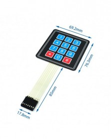
Hó/esőcsepp-érzékelő érzékelő modul, kétoldalas eső időjárási modul páratartalom az Arduino Robo számára
159 Ft 325 FtProduct description:
1. The sensor adopts high-quality FR-04 double-sided material, a large area of 5.0*4.0CM, and the surface is treated with nickel plating, which has better performance in terms of oxidation resistance, conductivity, and life;
2. Comparator output, clean signal, good waveform, strong driving ability, more than 15mA;
Adjusting the sensitivity of power distribution positioner;
4. Working voltage 3.3V-5V
5. Output form: digital switch output (0 and 1) and analog AO voltage output;
6. Equipped with fixing bolt holes for easy installation
7. Small board PCB size: 3.2cm x 1.4cm
Use a wide voltage LM393 comparator
Product use: Arduino robot kit, raindrops, rain sensor, can be used for monitoring various weather conditions, and converted into a digital signal and AO output.
Features:
Connected to the 5V power supply, the power indicator is on, and when there is no water drop on the sensor board, the DO output is high, the switch indicator is off, a drop of water is dropped, the DO output is low, and the switch indicator is on.
Brush off the water droplets on it, and then return to the output high-level state. . . .
The AO analog output can be connected to the AD port of the single-chip microcomputer to detect the amount of rain falling on it.
The DO TTL digital output can also be connected to the microcontroller to detect whether there is rain.
Wiring:
1. VCC: Connect to the positive pole of the power supply (3-5V)
2. GND: connect to the negative pole of the power supply
3. DO: TTL switch signal output
4. AO: analog signal output
Shipping list
1*Rain Sensor
1*Rain Module
2*Dupont Cables -
XL6009 DC-DC állítható tápegység-növelő modul Ultra LM2577, nagy teljesítményű, alacsony hullámosság
166 Ft 338 Ft15W power module with enable port
Size: 49(L)*23.4(W)*11.4(H) mm (without potentiometer)
Module parameters
Module nature: non-isolated boost module (BOOST)
Input voltage: 5-32V
Output voltage: (1) Continuously adjustable (5-50V)
(2) Fixed output 5V
Output current: 2.5A(MAX)
Input current: 4A (MAX)
Output power: natural cooling 15W, plus heat sink 25W (MAX) actual power
Maximum output power = input voltage * 4A * conversion efficiency
Output ripple: input 12V output 24 0.5A ripple 30MV 20M bandwidth
Operating temperature: (-40°C to 85°C) (Ambient temperature exceeds 40°C, please reduce power usage, or strengthen heat dissipation)
Full load temperature rise: 45℃
Working frequency: 400khz
No-load current: 5V to 12V 15mA, 8.4V to 12V 7mA, 12V to 24V 9mA, 12V to 36V 18mA, 24V to 48V 9mA, 24V to 36V 6mA.
Load Regulation: ±0.5%
Voltage regulation rate: ±0.5%
Dynamic response speed: 5% 200uS
Enable control port: yes, default high level 1.4V-VIN (ON)
Short circuit protection: none (please add a fuse or protection circuit to the input)
Input reverse polarity protection: none
Installation method: can be screwed (fixing hole 3 mm), 2 fixing holes
Wiring method: welding, after adding pins, it can be directly welded on the PCB -
XL6009 DC-DC buck-boost modul bemeneti széles feszültség alkalmazkodik a napelemes automatikus buck-boosthoz
177 Ft 362 FtModule description:
The voltage is pulled down to below 7V or less when the car starts, and as high as 15V or more at high engine speeds. It is difficult for electrical appliances working on 12V to work normally. This automatic buck-boost module solves this problem. No matter the input voltage is 5V, 12V or 32V, the output can be stabilized at 12V.
1. Ultra-wide input voltage range: 5V~32V;
2. Ultra-wide output voltage range: 1.25V~35V (with automatic buck-boost, within the working range, any voltage input can be regulated to any voltage
output);
3. Built-in 4A high-efficiency MOSFET switch, making the efficiency up to 94% ; (LM2577 current is only 3A)
4. The ultra-high switching frequency is 400KHz, the ripple is smaller, and the volume is smaller. (LM2577 frequency is only 50KHz)
5. The module adopts SEP IC topology circuit, which is a mature buck-boost solution.
6. The main chip adopts XL6009, with ultra-high switching frequency 400KHz, smaller ripple and smaller volume. (LM2577 frequency is only 50KHz)
Technical parameter:
Model Specifications---DSN6000AUD Automatic Buck-Boost Module
Module properties---non-isolated boost (BOOST)
Rectification mode---non-synchronous rectification
Input range---3. 8V~32V
Output range---1.25V~35V
Input current---3A (maximum), no-load 18mA (5V input, 8V output, no-load less than 18mA. The higher the voltage, the greater the no-load current.)
Conversion efficiency---<94% (the greater the pressure difference, the lower the efficiency)
Switching frequency---400KHz
Output ripple---50mV (the higher the voltage, the bigger the current, the bigger the ripple)
Load Regulation---±0.5%
Voltage regulation rate---±0.5%
Working temperature---40℃~ 85℃
Dimensions---48mm * 25mm * 14mm (L*W*H)
Instructions for use:
1. Connect to the power supply (5-32V), the power indicator light is on, and the module is working normally.
2. Adjust the blue potentiometer knob (usually turn clockwise to boost, counterclockwise
Step down) and use a multimeter to monitor the output voltage until it reaches the required voltage.
3. Some customers report that the output voltage of the module cannot be adjusted and is always equal to the input voltage. When you encounter this kind of problem, please turn it counterclockwise first
The potentiometer is more than 10 turns, and then the module can be used to adjust the voltage normally.
Precautions:
1. It is recommended to use the current within 2. 7A for long-term work. In order to ensure stable output, please maintain a minimum voltage difference of 1.5V.
2. The wiring is connected as shown in the connection diagram shown in the highlights. Please do not connect it in reverse. The wrong connection method may cause the power module to burn out.
Applications:
1. Vehicle regulated power supply, you only need to connect the input end of this module to the car cigarette lighter to supply power, you can adjust the potentiometer, and the output voltage can be
It can be adjusted arbitrarily at 1.25-30V to supply power to many devices such as your mobile phone, MP3, MP4, PSP charging, etc. It is very simple and convenient.
2. Power supply to electronic equipment, when the equipment needs 3-35V power supply and the corresponding voltage power supply in hand, this module can be used to easily convert the voltage
Adjust to the required voltage to solve the problem.
3. System working voltage test, when doing projects, you can use this module to debug the working voltage range of various voltage test systems, which is very easy and convenient
easy.
4. Applications with unstable voltage such as automobile voltage regulation, solar photovoltaic power generation, wind power generation, etc. -
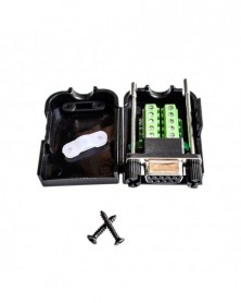
TTL-RS485 modul, automatikus hardveráramlás a vezérlőkártyához, RS485 kölcsönös átalakítás TTL jelre, egychipes
166 Ft 338 FtTTL to RS485 module RS485 mutual conversion to TTL signal Single chip microcomputer serial port UART lightning protection hardware automatic flow control
The power supply of this product is a wide voltage (3.0V~40V), which realizes the compatibility of 3.3V system and 5.0V system, and both 3.3V and 5.0V signals can be matched. This product is equipped with terminal blocks and silicone wire for direct wiring use. All original imported chips are used. It has strong performance, lightning protection design, strong anti-interference ability, industrial grade, and 1 year warranty!
This transparent transmission module realizes the mutual conversion of TTL signal and RS485 signal, but everyone must know that 485 is half-duplex communication. This communication method can realize two-way communication, but it cannot be carried out in both directions at the same time. Take turns alternately; that is to say, each segment of the communication channel can be the sender or the receiver, but at the same time, the information can only have one transmission direction.
Realize the automatic flow control of RS485 signal, automatic switching of the sending and receiving direction, using this module is as simple as operating the serial port.
Baud rate: 110~256000bps
Module features:
(1) This module fully considers the lightning protection design and anti-interference design of the 485 bus, and has extremely high EMC (electromagnetic compatibility) and EMI (electromagnetic anti-interference) performance. When long-distance transmission in the field, connect the "earth" end of the module Connecting to the earth can play a good role in anti-interference and lightning protection, making the 485 bus safer; it is not necessary to connect to the earth during indoor short-distance transmission.
(2) With standard 2.54 pitch pin headers, it is convenient for your secondary development
(3) It has a matching resistance of 120 ohms. Short-circuiting R0 can enable the matching resistance. It is recommended to short-circuit it for long-distance transmission.
(4) Support multi-machine communication, at least 40 nodes can be connected to the same network
(5) It can be hot-swapped, and the signal will not be blocked
(6) Anti-interference wiring and copper laying method to prevent signal interference -
6 szál 22V24V-os elektromos kéziszerszám, napelemes világítás, 18650 speciális lítium akkumulátor védőlap BMS
162 Ft 330 FtNote: The lithium battery protection board cannot be used for lithium iron phosphate batteries, hernia lights, hand drill battery packs, electric fish machine battery packs, electric bicycle battery packs, children's car batteries, power motors above 550, and 1W fisheye LEDs. Lamps, please pay attention to customers who purchase the above combination! .
The power range described is applicable to the following products:
Massager battery pack, LED lamp backup power supply, 12V electronic products, solar street lamp battery pack, monitoring backup power supply, and other products.
Note: For products with a current above 3A, the battery discharge rate must be above 3C.
The magnification calculation formula: for a battery with a 1C magnification, the capacity of 2000 is equal to 2AH*1=2A working current.
3C rate battery, 2000 capacity is equal to 2AH*3=6A working current.
In use, the battery will heat up, which means that the battery rate is not applicable. In this case, the battery cannot be used for a long time, and the battery will be damaged quickly.
Note 1: Wiring 0V(B-), 3.7V(B1), 7.4V(B2), 11.1V(B3), 14.8V(B4), 18.5V(B5), 22.2V(B ) strictly according to the diagram, Don't short circuit on purpose!
Note 2: After the line is connected, it needs to be charged before output.
Note 3: When connecting 6 groups of batteries in series, please ensure that the voltage of each group of batteries is the same. If they are not the same, please charge each group of batteries separately and then use them in series. During the discharge test, the battery with the fastest voltage drop is the poor battery.
Explain: Don't mix good batteries and bad batteries together! The closer the capacity/internal resistance of the 6 groups of batteries, the better! (4 good batteries 2 bad batteries = 6 bad batteries).
Description and explanation:
6 strings (for 6 18650 batteries or polymer lithium batteries in series combination)
21.6V (rated voltage of polymer battery)
22.2V (18650 or 3.7V lithium battery rated voltage)
25.2V (Voltage after fully charged lithium battery)
Discharge 22A (refers to the upper limit discharge current limit)
6serieslithiumionbatteryprotectionboardelectricalparameters
Basic item
Specification
Unit
Remarks
Current
Continuous discharge current
14
A
Instantaneous discharge current
22
A
Recharge
Charging voltage
Lithium battery charger 25.2V
V
recharging current
25(MAX)
A
Overcharge protection
Overcharge detection voltage
4.28±0.05
V
Single core
Overcharge protection delay
0.5
S
Overcharge release voltage
4.08±0.05
V
Single core
Power balance
Cell balance detection voltage
/
V
Cell balance release voltage
/
V
Cell balance current
/
mA
Over discharge protection
Over discharge detection voltage
2.55±0.08
V
Over discharge detection delay
0.1
S
Over discharge release voltage
2.9±0.1
V
Overcurrent protection
Overcurrent detection voltage
150
mV
Overcurrent detection delay
9
MS
Overcurrent protection current
75±5
A
Overcurrent protection release condition
Disconnect load
Short circuit protection
Short circuit protection conditions
Short circuit of external load
Short circuit detection delay
250
uS
Short circuit protection release condition
Disconnect load
Temperature protection
Temperature protection
/
℃
On demand
Internal resistance
Main circuit conduction internal resistance
≤20
mΩ
Self-consumption
Working current
≤30
uA
Sleep current(when the battery is over-discharged)
≤10
uA
Operating temperature
temperature range
-30~ 80
℃
size
/
53.5*35.5*3.6
mm
weight
/
8
g