Kereskedelmi, irodai és ipari
-
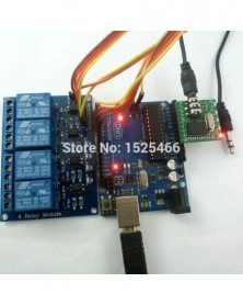
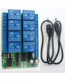
DTMF Audio Remote Relay Kit MT8870 Telefon Hangdekóder vezérlés DC 5V 12V 24V 48V Feszültség_Arduino DUE UNO MEGA Raspberry
1 187 Ft 2 423 FtProduct Name: DTMF Audio Remote Relay Kit MT8870 Phone Voice Decoder Control DC 5V 12V 24V 48V Voltage for_Ardiuno DUE UNO MEGA Raspberry pi
Module No.: CE005
Package:(Does not include UNO/MEGA2560 Board):
1 PCS DC5V 4 Channel UNO/MEGA2560 Relay Board ;
1 PCS MT8870 DTMF decoder module;
1 PCS Male to Male audio wire (3.5mm jack );
Description:
DC5V 4CH Ardiuno Relay Board:
5V 4-Channel Relay interface board,and each one needs 15-20mA Driver Current
Relay can Control DC 1-48V Circuit OR AC85-265V Circuit
Indication LED's for Relay output status
Size : 75mm*55mm*19.3mm
MT8870 DTMF decoder module:
Onboard Complex Frequency Decoder IC MT8870DS
DC Power Supply Voltage:4.5V-5.5V(Typical: 5V)
Operating Temperature :-40- 85 °C
IO Drive : Current Maximum 10mA.
PCB Size : 25.4x25.4MM
For more decoder module information, please click here
uno/mega2560 Code fragment:
After purchase, please contact me for complete code!
//*******************************************//
#include
int STD = A0;
int Q1 = A1;
int Q2 = A2;
int Q3 = A3;
int Q4 = A4;
int CH1 = 2;
int CH2 = 3;
int CH3 = 4;
int CH4 = 5;
....
//Check once every 5 ms
void dtmf_decode(void)
{
....
}
void setup()
{
.....
}
void loop()
{
//Complete the decoding
if(Decod_finished)
{
Decod_finished = 0;
switch(Q_dat){
case 1 : Serial.print(" Activate : Channel 1 \n" ); digitalWrite(CH1, LOW);delay(delay_time);digitalWrite(CH1, HIGH); break;
case 2 : Serial.print(" Activate : Channel 2 \n" ); digitalWrite(CH2, LOW);delay(delay_time);digitalWrite(CH2, HIGH);break;
case 3 : Serial.print(" Activate : Channel 3 \n" ); digitalWrite(CH3, LOW);delay(delay_time);digitalWrite(CH3, HIGH); break;
case 4 : Serial.print(" Activate : Channel 4 \n" ); digitalWrite(CH4, LOW); delay(delay_time);digitalWrite(CH4, HIGH);break;
default : Serial.print("Invalid channel \n" ); break;
}
.....
//****************************************************************************//
-
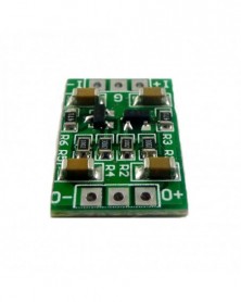
Szín: - 3 DB 10-300MA 3V 3.6V gombelem Újratölthető lítium akkumulátor Töltéskezelő modul 3.3V 4.2V Töltő NI-MH Ni-CD
430 Ft 877 Ft
Product Name: 10-300MA 3V 3.6V Coin Cell Rechargeable lithium battery Charge management module 3.3V 4.2V Charger for NI-MH Ni-CD Li-ion LiFe
Packing list:
3 PCS 3V 3.6V NI-MH Ni-CD Li-ion Li-Polymer Coin Cell Rechargeable lithium battery Charger
(Please choose the parameters you need when purchasing)
Description:
3.3V A Version :
Input voltage : DC 3.9-6V(Recommend DC 4.2V/4.5V/5V)
Charging voltage : 3.3V
Charging current : 50A/100MA/200MA
Charge the 3V rechargeable Coin Cell battery.
Such as: VL2330 ML2032 ML1220 MS621 ML2016 MS414GE
4.2V B Version :
Input voltage : DC 4.5-6V(Recommend DC 5V)
Charging voltage : 4.2V
Charging current : 50A/100MA/200MA
Charge the 3.6V rechargeable Coin Cell battery OR 3.7V lithium battery.
Such as:LIR1054 LIR1220 LIR1254 LIR1454 LIR1620 LIR1632 LIR1654
LIR2016 LIR2025 LIR2032 LIR2050 LIR2430 LIR2450 LIR2477 CR2477
Automatic charge current adjustment based on the output capability of input power supply
Suitable for Solar-Powered System
Suitable for Charging Manganese Lithium, LiFePO4 and Lithium Coin Battery
Precharge Conditioning for Reviving.Deeply Discharged Cells and Minimizing Heat. Dissipation During Initial Stage of Charge
Constant Charge Current from 10mA to to 300mA(By changing the RCS resistance)
Constant-Current/Constant-Voltage Operation with Thermal Regulation to Maximize Charge Rate Without Risk of Overheating
Automatic Low-Power Sleep Mode When Input Supply Voltage is Removed
C/10 Charge Termination
Automatic Recharge
Operating ambient temperature : -40° to 85°
Storage temperature : -65° to 125°
Size 15.3mm x 10.2mm x 2.5mm(very small)
Weight : 0.45g(Very lightl)
Please contact me for detailed chip manual
The CB06CRMA is a complete constant-current /constant voltage linear charger for coin batteries. The device contains an on-chip power MOSFET and eliminates the need for the external sense resistor and blocking diode. An on-chip adaptive block can adjust charging current automatically based on the output capability of input power supply, so CB06CRMAis ideally suited for solar powered system. Thermal feedback regulates the charge current to limit the die temperature during high power operation or high ambient temperature.
The regulation voltage is internally fixed at 3.3V with 1% accuracy, it can also be adjusted upwards with an external resistor. The charge current can be set externally with a single resistor. When the input supply is removed, the CB06CRMA automatically enters a low power sleep mode , dropping the battery drain current to less than 3uA. Other features include undervoltage lockout, automatic recharge and charging indicator.
Application:
Wearable equipment
Smart home
Medical equipment,Calculator
Water meters, gas and electricity
Measuring instruments, sensors
for <1000MA Polymer lithium battery
for <1000MA Li-ion lithium battery
-
Szín: - DC 12V 24V 8I8O többfunkciós Modbus RTU relémodul támogatás 03 06 16 Funkciókód RS485 kapcsolóvezérlő kártya
1 575 Ft 3 215 Ft
Product Name: DC 12V 24V 8I8O Multifunction Modbus RTU Relay Module Support 03 06 16 Function Code RS485 Switch Control Board DIN35 Rail Box
Package inlcuded:
1PCS DC 12V/24V 8 IO Input & 8 Output DIN35 C45 Rail Box RS485 Relay Module
If you need standard Modbus RTU protocol, need more reliable relay, need RS485 interface with TVS, please click here: click here
Description:
1: DC 12V (12V Version), DC 24V (24V Version)
2: Standby current (all relays closed) 13MA, 1 relay open 41MA, 2 relays open 69MA, 3 relays open 95MA,4 relays open 123MA,5 relays open 149MA,6 relays open 174MA, 7 relays open 198MA,8 relays open 225MA
3 8 photoelectric isolation Input ports (NPN low level active ), the input and output relationship can be set to associated (default) and non-associated through commands.
4: ''open'' ''close'' ''Momentary'' ''Self-locking'' ''Interlock'' ''Delay'' 6 Commands
5: MODBUS RTU command, Support 03 06 16 function code
6: Under the ''Delay'' command ,the maximum delay is 255 seconds;
7 MODBUS commands can be made serial HyperTerminal (serial assistant) OR ''Modbus Poll'' Enter;
8 Under the MODBUS command mode, it can support up to 64 devices in parallel
9 The default baud rate is 9600BPS. The baud rate can be selected through jumpers: 2400 4800 9600 19200BPS
10 Size: 136 * 72 * 20mm(Only PCB Board);140 * 88* 42mm(with Din Rail Box)
11 Weight: 134g(Only PCB Board);223g(with Din Rail Box)
12 Maximum load: 10A / 250VAC, 10A / 125VAC, 10A / 30VDC, 10A / 28VDC, 10A / 12VDC
For more information, please contact me
DIN rail Box parameters:
Product model: UM72
Color: green
Width: suitable for PCB board width UM72(72mm)
Insulation grade: flame-retardant VO grade
Backplane length: suitable for 136 mm PCB boards
Net weight: 99g
Installation: DIN35 and C45 rail
Application
PLC IO expansion board
Smart Home,Home Automation ,Wiser Home;
PTZ CCTV Camera
Security Monitoring
Identification system;
Motor FW & BW
Automatic curtain control
Typical applications:
1 The dial switch (slave address) is invalid and can only control one module at a time.
MODBUS RTU command mode (HEX), you can control a variety of ways: Serial Hyper Terminal Control (need to manually add the CRC), Modbus Poll software control (software automatically add the CRC), PLC or MCU process control
Wiring Diagram:
1 DC 12V/24 control circuit,Wiring diagram below. ''LOAD'' may be camera,LED lights, fans, motors and other DC 12V/24V equipment
2 DC 1-110V OR AC 85-265V control circuit,Wiring diagram below(Note:If not DC 12V/24V load, need another DC 12V/24V power supply). ''LOAD'' may be LED lights, fans, motors Lights, fluorescent lights, solar water heaters and other DC AC equipmen
Test Software(We offer a demo video):
Serial HyperTerminal:
Modbus Poll -
Szín: - Többcellás 2S 3S 4S Type-C – 8,4 V 12,6 V 16,8 V Step-Up Boost LiPo polimer Li-Ion töltő 7,4 V 11,1 V 14,8 V
293 Ft 597 FtProduct Name: Multi-Cell 2S 3S 4S DC 3-6V To 8.4V 12.6V 16.8V Step-Up Boost LiPo Polymer Li-Ion Charger 7.4V 11.1V 14.8V 18650 Lithium Battery
Packing list:
1 PCS 2/3/4-cell 7.4V 11.1V 14.8V Type-C 3-6V Boost Li-Ion battery charger
(Please select the appropriate version according to your battery voltage and power supply current before buying)
Description:
2-Cell(2S) 8.4V Version:
Input voltage : DC 3-6V(Recommend DC 3.7V 5V)
Input current : 1A(1A Version);2A(2A Version);4A(4A Version)
Charging voltage : 8.4V
Charging current : 0.55A(1A Version);1.1A(2A Version);2.2A(4A Version)
3-Cell(3S) 12.6V Version:
Input voltage : DC 3-6V(Recommend DC 3.7V 5V)
Input current : 1A(1A Version);2A(2A Version);4A(4A Version)
Charging voltage : 12.6V
Charging current : 0.37A(1A Version);0.74A(2A Version);1.48A(4A Version)
4-Cell(4S) 16.8V Version:
Input voltage : DC 3-6V(Recommend DC 3.7V 5V)
Input current : 1A(1A Version);2A(2A Version);4A(4A Version)
Charging voltage : 16.8V
Charging current : 0.28A(1A Version);0.56A(2A Version);1.12A(4A Version)
Switching Frequency up to 1MHz
Quasi-CV mode to Compensate for the Voltage Loss on Battery Internal Resistance and Trace Resistance
Automatic Recharge
Protection for Battery Voltage Being Low than Input and Short Battery
Good adaptability to Input Supply with Limited Driving Capability
Battery Overvoltage Protection
Led indicator : ''CR'' LED is charge status indicator
''OK'' LED is fully charged OR Constant voltage mode;
Operating Ambient Temperature-40℃ to +85℃
Size 39mm x 18mm x 6.3mm
Weight : 5g
Applications:
PDA, MP3 Players, MP4 Players
Digital Cameras
Bluetooth Applications
Game Players
Notebook
li-on li-po Lithium Battery 18650
Mobile phone
Solar charging
Audio equipment
Portable Devices
POS , Electric Fan
TYPE-C charging equipment
The input current is determined by the value of the two RCS
The charging voltage is determined by the chip and cannot be modified by resistance
-
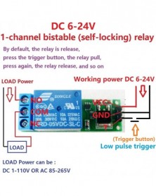
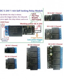
mini 6-24V flip-flop retesz relé modul Bistabil önzáró kapcsoló Alacsony impulzusú triggerkártya
265 Ft 541 FtProduct Name:mini 6-24V Flip-Flop Latch Relay Module Bistable Self-locking Switch Low pulse trigger Board
Packing list:
1 pcs 1 Channel DC 6-24V Self-locking Relay Module
If you need 5V version, click here
Description:
Working voltage: DC 6-24V
Working current: 60-70MA
Standby current: 1UA
Load current : AC 250V/10A, DC 30V/10A
Trigger mode: Low pulse trigger
Size: 48mm * 16mm * 18.5mm (L * W * H), Very small size
Weight: 14.3 g
This is a bistable (self-locking) relay module,Trigger once, the relay pull (and holds);Trigger again, the relay releases (and holds)
Module interface:
1. VCC: positive power supply (VCC)
2. GND: negative power supply (GND)
3. T : Low pulse trigger
Relay outputs:
1. NO: normally open relay interface
2. COM: Common Interface Relays
3. NC: normally closed relay interface
USE : By default, the relay is release, press the trigger button, the relay pull, press again, the relay release, the third press, the relay pull, and so on
Typical applications:
Automotive electronics
Industrial equipment
Motor
LED
Smart Home
Emergency lighting
MCU development board
Toy car
-
8CH IIC I2C logikai szintátalakító kétirányú modul és DC-DC 5V–3,3V Setp-dowm Buck AMS1117 tábla For_Arduino
150 Ft 307 FtProduct Name : 8CH IIC I2C Logic Level Converter Bi-Directional Module & DC-DC 5V to 3.3V Setp-dowm Buck AMS1117 Module For_Arduino Breadboard
No matter how many pieces you buy the board, you only need to pay 1 piece Shipping costs
Module No.: TB371
Packing list:
1 pcs 2 in 1 5V to 3.3V DC-DC Buck Module & 8 channels Logic level converter;
Description:
1 On board DC 5V to 3.3V DC-DC Step-Down Power Supply Buck Module,IC AMS1117-3.3;
2 On board 8 channels 5V to 3.3V(also 3.3V to 5V) Logic level converter,base Limiting resistor;
3 Arduino Breadboard friendly;
4 PCB size:25* 15mm
Level conversion principle:
Between 5V and 3.3V level plus 470 ohm current limiting resistor, to avoid being burned of 3.3V port.
So, when the LOW side no-load, HIGH side plus 5V level,LOW side test is still at 5V level,vice versa.
This is a normal phenomenon, not the level conversion function does not work.
Schematics:
-
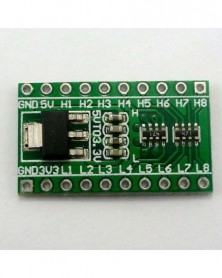
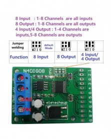
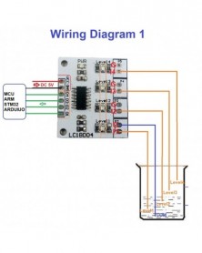
Szín: - 8 csatornás bemeneti/kimeneti UART RS485 Modbus RTU vezérlő PLC bővítőkártya Arduino UNO MEGA NANO STM32 AVR PIC
319 Ft 651 Ft
8ch Input/Output UART RS485 Modbus RTU Controller PLC Expansion board for Arduiuo UNO MEGA NANO STM32 AVR PIC
Package inlcuded:
1 x 8-channel Multifunction input Output module(Please select the version you need)
Description:
1 Working voltage: DC 12V (6-25V)
2 Working current: 9-16MA
3 MODBUS RTU 03 06 16 command control mode
4 Three functional modes can be selected by jumpers: 8 channel input/8 channel output/4 input 4 output
5 Input mode: support 3.3V/5V TTL level input, there are two input modes: low level input (default) and high level input
6 Output mode: 5V/3.3V TTL level, low level (default)/high level output
7 In MODBUS command mode, it can support up to 247 devices to be used in parallel
8 Input port status supports query (default) and automatic reporting
9 The default baud rate is 9600BPS, which can be configured to support 1200 2400 4800 19200 baud rate
10 Size: 44*31*15
11 Weight: 9 grams (no Pin), 10 grams (with Pin), 12.5 grams (with Terminals)
Instruction manual Please ask us after the purchase
Application
Automated industry PLC
UNO MEGA MCU AVR STM32
Digital in to RS485/RS485 to Digital out
Smart Home,Home Automation ;
Identification system;
CCTV Camera PTZ Control;
Security system;
LED dot matrix screen;
RS485 remote control;
Choose different functions through jumpers on the board:
As 8-channel inputs Please refer to ''N4DIG08 MODBUS RTU instruction (8-channel input)''
As 8-channel outputs Please refer to ''N4DIG08 MODBUS RTU instruction (8-channel output)''
As 4 input 4output Please refer to ''N4DIG08 MODBUS RTU instruction (4 Input 4 Output)''
As an 8-channel input wiring diagram:
As an 8-channel output wiring diagram:
As a 4 input 4 output wiring diagram:
RS485 Wiring diagram:
-
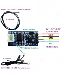
Szín: - -20-125 Celsius RS485 TTL RS232 hőmérséklet érzékelő átalakító modul 10K 3950 NTC termisztor ellenálláshoz
174 Ft 355 Ft
Product Name: -20-125 Celsius RS485 TTL RS232 Temperature Sensor Converter Module for 10K 3950 NTC Thermistor Resistor replace DS18B20 PT100
Packing list:
1 pcs NTA8A01 RS485-TTL232 NTC Thermistor sensor converter(Please choose the version you need)
NTA8A01 NTC Temperature converter Module Description:
Working voltage: 5V version: DC 3.7-5.5V; 12V version: 6-25V
Working current: 8-13MA
MODBUS RTU protocol, 03 read command, 06 write command.
Serial port baud rate: 9600 (default), N, 8, 1
By modifying the 485 address, up to 247 modules can be cascaded (more than 16 please use R485 repeater)
Adapted sensor: B3950 10K 1% NTC thermistor Resistor
Temperature measurement range (using our NTC sensor): -20 ° C to 125 ° C.
Temperature measurement accuracy (using our NTC sensor): 1% .
Size: 30 X 15 X 6MM
Weight: 5V version 2g, 12V version 2.5g
For more information, please contact us!!!
NTC sensor specifications:
Product Name: 5*25mmNTC Waterproof Probe
Total length : 50CM
Resistance value: 10K
Resistance accuracy: ±1%
Resistance B value: 3950 ± 1%
Temperature range: -20 ° C -125 ° C
Wire size: 2651 26# parallel line temperature 105 °C
Plug model: XH2.54-2P
NTC Probe: A version without mounting holes, B version with mounting holes (4MM/M4)
Note:
1 This module does not have an NTC sensor. The NTC sensor needs to be purchased separately (B3950 10K 1% );The module's measured resistance value is 1% , and the theoretical temperature range is -273-200°C. The final temperature measurement accuracy and temperature range are determined by NTC thermistor.
2 Be sure to use the correct sensor (B3950 10K 1% NTC), otherwise the temperature will not be accurate
Typical application:
PLC control system
NTC thermistor sensor
Thermostatic Controls
Industrial Systems
Thermometers
Thermally Sensitive Systems
Indoor and outdoor temperature measurement
Temperature in vegetable garden
Weather forecasting, and monitoring
Temperature in Computer Room
Warehouse temperature
-
Szín: - DC 5V 4 digitális vízszintjelző tábla folyadékérzékelő vezérlő modul az Arduino UNO NANO haltartály
177 Ft 361 Ft
Product Name: DC 5V 4 Digital Water Level Indicator Board Liquid Sensor Controller Module for Arduiuo UNO NANO Fish tank Water tower
8 channel version click: click here
Package inlcuded:
1x DC 5V 4 Digital Water Liquid Level Indicator Module
Description:
1 Working voltage: DC 5V
2 Working current 7-12MA
3 One power indicator light, four water level indicator lights
4 Four water level output interfaces (low level 0V, high level 3.7V),for MCU IO
5 Four water level sensor interfaces (2P XH2.54)
6 Size: 32mm X 28mm X 11mm(With Pin),32mm X 28mm X 3.5mm(No Pin)
7 Weight: 4.6g(With Pin),3.3g(No Pin)
8 channel version click: click here
Note:
1 Package does not contain probe (wire).2P Male XH2.54mm Pitch Wire Cable can be used as a probe,which can be purchased separately or prepared by yourself.
2 For safety, use an DC power supply with good isolation
Application
for Arduiuo UNO MEGA2560 NANO IO
for FPGA/CPLD ARM STM32
Home water tower automatic water supply system
Aquarium Fish tank Water Changer System
Fill the water tower automatically
Automatic pumping from water tower
Conductive liquid automatic control
Automatic feeding system for poultry and livestock
Farm automatic water supply system
And other occasions that require automatic water supply and water exchange.
Solenoid valve water pump motor automatic control
Interface description:
VCC :Power of positive(DC 5V)
GND :Power of negative(DC 5V)
D1 D2 D3 D4: water level output interfaces (low level 0V, high level 3.7V)
I1 I2 I3 I4 : water level sensor interfaces (2P XH2.54)
Wiring diagram:
Make the probe(Need to be purchased separately):
1 Prepare 2PCS(or more) XH2.54MM wires
(You can prepare this kind of wire by yourself, or buy it from our shop)
2 Multiple wires can be spliced to lengthen the probe length.
(Please do waterproof treatment at the splicing.)
3 Please cut the female interface short and keep a distance of 5-10MM
(This prevents water droplets from sticking to the probe. )
-
2db 100mw UART RS232 vezeték nélküli RF adó-vevő 2.4G modul Arduino UNO-hoz
1 134 Ft 2 315 FtProduct Name:2 pcs 100mw 2.4G Serial ports Wireless Transmit & Receive RF Transceiver Module 5V 3V TTL232 for Arduiuo UNO Internet of things
Packing list:
2 pcs 2.4G 100mw RS232(TTL Lever) Wireless Transceiver Module
Overview:
The transceiver module is based on 2.4GHz frequency band wireless transparent data-transmission module.
This Module supports most basic AT commands: baud rate, ID number, frequency settings and inquiries; factory settings; version information.
When the module is in AT module, users can use serial-port to issue AT commands to set the module's parameters.
When the module is in transparent data transfer mode, the user transmit data, frame number data module, add packaged rowcount, and then automatically transmit , at reliable range, the module will automatically re-transmit data to ensure successful transmission.
Performance Parameter:
Working voltage: 3.3V-5.5V;
RS232 Interface ( 3.3V/5V TTL level)
Frequency range: 2402~2482MHz
Transmit power: 20dBm(100mw);
Receiver sensitivity: -87dBm;
Operating temperature: -40~ 85 ° C;
Transparent transmission mode baud rate:
2400,4800,9600(Default),14400,19200,38400,57600,115200,12800,25600
AT mode configured baud rate fix is: 9600;
Open ground Transmission distance : 300-400M
Pinout :
1, VDD:3.3V-5V power supply ;
2, GND: Power Ground;
3, TXD: serial port output, MCU or USB to serial port RXD;
4, RXD: serial port input, MCU or USB to serial port TXD;
5, CMD: Enter PIN AT mode, active low level;
AT Commands Data Sheet : Please leave a message ;
Typical applications:
2402-2482MHz ISM/SRD band systems
for Arduiuo UNO MEGA2560 DUE MCU
Consumer electronics
Internet of Things
Access control, Attendance, Logistics
Smart Furniture
Robert
Wireless sensor
Smart Home / Home Automation
Application example:
Wireless communication between UNO and PC(Also application with other 3.3V/5V level MCU ,for example: Raspberry pi FPGA/CPLD STM32 C8051 C51 PIC AVR MSP430)
for this Applications you also need:
1: USB to ttl cable; Click here
2: UNO/MEGA2560/DUE; Click here
ARDUIUO IDE Serial data Transceiver:
Copy the following code:
//----------------------------------------------------------------------//
// Pin 13 has an LED connected on most ARDUIUO boards.
int led = 13;
String comdata = "";
void setup()
{
// initialize the digital pin as an output.
pinMode(led, OUTPUT);
Serial.begin(9600);
Serial.println("Hello, I am Arduiuo!");
}
//Serial data transceiver
void loop()
{
while (Serial.available() > 0)
{
digitalWrite(led, HIGH); // turn the LED on (HIGH is the voltage level)
comdata = char(Serial.read());
delay(2);
}
if (comdata.length() > 0)
{
Serial.println(comdata);
comdata = "";
}
digitalWrite(led, LOW); // turn the LED off by making the voltage LOW
}
//----------------------------------------------------------------------// -
AD22B04 DC 12V 4ch MT8870 DTMF hangjel dekóder telefon hangos távirányító relé kapcsoló modul LED motor PLC intelligens
1 321 Ft 2 695 FtTypical applications:
Home lighting system
DTMF Remote control switch
Smart Home / Home Automation
DC 12V LED lighting
Fluorescent lamp
12V DC Motor
Fluorescent lamp
Automotive electronics
Industrial automation and control
Control 4 Channel DC 12V electrical equipment: LED / Automotive electronics
General electrical equipment control:DC 1-110V or AC 85-265V
All kinds of motor reversing control: DC 1-48V or AC 85-265V
Product Name: AD22B04 DC 12V 4ch MT8870 DTMF Tone Signal Decoder Phone Voice Remote Control Relay Switch Module for LED Motor PLC Smart Home
Packing list :
1 PCS AD22B04 DC 12V 4 Channel DTMF Decoder Relay Board ;
1 PCS Male to Male audio wire (3.5mm jack );
Functional characteristics:
1 Product model: AD22B04
2.working voltage DC 12V, with reverse polarity protection
3.Operating Current: Standby 11-13 MA, 1 relay "open" 44MA, 2 relays "Open" 77MA, 3 relays "Open" 110MA, 4 relays"open" 140MA
4 eight modes of operation:Non-locking (Momentary ), self-locking (Toggle),inter-locking (Latch), 5/20/60/120/250-second delay
5 The default control command is 1/2/3/4.Example: Dial 1 to control relay 1, dial 2 to control relay 2, dial 3 to control relay 3, dial 4 to control relay 4; control commands can be changed any 1-4 bits. (For more details, refer to " AD22B04_4 channel DTMF controller commands setting manual ").
6 Size: 50 * 80 * 19.5mm
7 Weight: 59 grams
8 Maximum load: 10A / 250VAC, 10A / 125VAC, 10A / 30VDC, 10A / 28VDC, 10A / 12VDC
Use Method:
This is the DTMF audio controller with four channels, any phone or fixed telephone with DTMF key code remotely controls product relay "open" and "close".(the majority of smartphones and functions machine are DTMF code). Our software "DTMF Dial" (installed in a computer) can be also provided to control relays.
As shown above, by phone remote control relay. You need two phones, one as a receiver (phone_1), the other one as a transmitter (phone_2); mobile phone_1 connected by DTMF audio cable 3.5MM audio controller (the controller to be powered), and then using phone_2 ( may be a fixed telephone) call the phone_1, phone_1 answered, so that two phone call each other; then dial 1/2/3/4 by phone_2 keypad to control four relays .
As shown above, you can install one of our "DTMF Dial" software in your computer, through the software control DTMF audio controller. At first, use 3.5MM audio cable to the computer video port and audio port controller, then click on the software to control relays 1/2/3/4.
Caution:
1 DTMF audio controller must use stable work of DC 12V power supply (recommendations 1A or above the power adapter)
2 remote control the controller by a mobile phone, the receiver must be the phone with 3.5MM audio interface, the transmitter can be a cell phone or landline
3 as a receiver of the phone or a computer installed the "DTMF Dial" software must output a sound (not muted), or they will not control relays.
Glossary:
NO: Normal open
COM: Common terminal
NC: Normal Connect
Relay open: COM connected NO but disconnected NC
Relay close: COM disconnected NO but NC connected COM.
Non-locking (Momentary ): Dial 1 (2/3/4 is the same), relay 1 "Open", relay close after 1 second delay
Self-locking: Dial 1, relay 1 "Open", dial 1 again, relay 1 "off", and so on
Inter-lock: Dial 1, relay 1 "Open", other relays "Off"; dial 2, relay 2 "Open", other relays "off", and so on
"Delay": Dial 1, relay 1 "Open", relay 1 "Close" after a time
Mode selection:
Eight modes of operation, electric iron jumper (picture above) on the pads
-
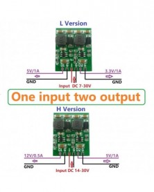
Szín: - Bemenet -feszültség Kimenet -2,5V 3,3V 5V 7,5V 10V 12V Precíziós feszültség Referenciaforrás kártya Cserélje
172 Ft 350 FtClick on the picture or search SKU for product details
We are a professional manufacturer, if you don't find the product you need, please contact us directly.
Product SKU Click Picture Description
Boost-Buck
to - voltage DD0315NA
Input voltage : DC 3~ 15V,
Output : DC -3.3V -5V -6V -9V -12V -15V;
Maximum output current : 180-500MA
Boost-Buck
to - voltage DDUB12NA Input voltage : DC 4.8V- 28V,
Output : DC -5V/-10V/-12V/-15V;
Maximum output current : 250-500MA
Boost
to /-voltage DD1718PA Input voltage : DC 3~ 18V,
Output : DC ±5 ±6 ±9 ±12 ±15 ±24
Maximum output current : 100-200MA
Boost-Buck
to /-voltage DD39AJPA Input voltage : DC 3.6~ 30V,
Output : DC ±3~±30V adjustable
Maximum output current : 200-3000MA
Boost-Buck
to /-voltage DD1912PA Input voltage : DC 3~ 24V,
Output : DC ±5V/±6V/±9V/±10V/±12V/±15V/±18V±24V
Maximum output current : 100-1000MA
1% /-voltage
reference Module ZD3605PA Input voltage : DC -3.5~ -20V,
Output : DC ±2.5V ±3.3V ±5V ±7.5V ±10V ±12V
Maximum output current : 14MA
Product Name: Input -Voltage Out -2.5V 3.3V 5V 7.5V 10V 12V Precision Voltage Reference source Board Replace AD584 LM399 LM4040 AD588
Packing list:
1 PCS TL431 voltage reference source Module
Description:
TL431 Positive & Negative Dual Output ±1% Precision voltage reference source Module
±2.5V :
Input Voltage ±3.5-10.1V,Output Voltage ±2.5V
Input Current 2.5-16MA,MAX Output Current 0.6-14MA
±3.3V :
Input Voltage ±4.3-10.9V,Output Voltage ±3.3V
Input Current 2.5-15MA,MAX Output Current 0.6-13MA
± 5V :
Input Voltage ±6-12.6V,Output Voltage ±5V
Input Current 2.1-16MA,MAX Output Current 0.1-13MA
±7.5V :
Input Voltage ±8.5-15.1V,Output Voltage ±7.5V
Input Current 3-16MA,MAX Output Current 1-14MA
±10V :
Input Voltage ±11-17.6V,Output Voltage ±10V
Input Current 3-15MA,MAX Output Current 1-13MA
±12V :
Input Voltage ±13-19.6V,Output Voltage ±12V
Input Current 3-14MA,MAX Output Current 1-12MA
Accuracy : ±1%
Operating temperature range : -40~ 125 Degrees Celsius
Storage temperature range : -65~ 150 Degrees Celsius
2.54mm pin pitch,for MCU Development Board Breadboard friendly.
Size : 19*13*2.8mm
Weight : 0.9g
Note:
1 This is a voltage reference source, and its output current is small and cannot be used as a power supply.
2 If the input voltage is too small or the output current is too large, the output will be distorted
3 If the input voltage is too large, the module will heat up
Applications
Operational Amplifier : LM324 LM358 AD101 AD201 Etc.
ADC : ADC0809 MAX160 AD7705 Etc.
DAC :DAC0832 PCF8591 TL5615 MPC4822 TL5610
Replace AD584 LM399 LM4040 MC1403 LM326 AD637 AD584
Audio equipment
RS232 RS485 RS422 Bus
LCD voltage reference
Instrumentation equipment
Wifi/Router/Ethernet devices
-
AD22A08 DC 12V 8 csatornás DTMF relé MT8870 dekóder telefon távirányító kapcsoló
1 883 Ft 3 843 FtTypical applications:
Home lighting system
DTMF Remote control switch
Smart Home / Home Automation
DC 12V LED lighting
Fluorescent lamp
12V DC Motor
Fluorescent lamp
Automotive electronics
Industrial automation and control
Control 8 Channel DC 12V electrical equipment: LED / Automotive electronics
General electrical equipment control:DC 1-110V or AC 85-265V
Product Name: AD22A08 DC 12V 8 channels DTMF Relay MT8870 Decoder Phone Remote Control switch
Packing list :
1 PCS AD22A08 DC 12V 8 Channel DTMF Decoder Relay Board ;
1 PCS Male to Male audio wire (3.5mm jack );
Functional characteristics:
1 Product model: AD22A08
2.working voltage DC 12V, with reverse polarity protection
3.Operating Current: Standby 11-13 MA, 1 relay "open" 44MA, 2 relays "Open" 77MA, 3 relays "Open" 110MA, 4 relays"open" 140MA, 5 relays open 170MA,6 relays open 197MA,7 relays open 223MA,8 relays open 247MA.
4 Eight modes of operation:Non-locking (Momentary ), self-locking (Toggle),inter-locking (Latch), 5/20/60/120/250-second delay
5 The default control command is 1/2/3/4/5/6/7/8.Example: Dial 1 to control relay 1, dial 2 to control relay 2, dial 3 to control relay 3, dial 4 to control relay 4; control commands can be changed any 1-4 bits. (For more details, refer to " AD22A08_8 channel DTMF controller commands setting manual ").
6 Size: 94 * 62 * 19.5mm
7 Weight: 114 grams
8 Maximum load: 10A / 250VAC, 10A / 125VAC, 10A / 30VDC, 10A / 28VDC, 10A / 12VDC
Note:
1 Please use a small ripple DC power supply (Recommended: Power with earth wire)
2 Please adjust the sound output to 80-90%
Use Method:
This is the DTMF audio controller with four channels, any phone or fixed telephone with DTMF key code remotely controls product relay "open" and "close".(the majority of smartphones and functions machine are DTMF code). Our software "DTMF Dial" (installed in a computer) can be also provided to control relays.
As shown above, by phone remote control relay. You need two phones, one as a receiver (phone_1), the other one as a transmitter (phone_2); mobile phone_1 connected by DTMF audio cable 3.5MM audio controller (the controller to be powered), and then using phone_2 ( may be a fixed telephone) call the phone_1, phone_1 answered, so that two phone call each other; then dial 1/2/3/4 by phone_2 keypad to control four relays .
As shown above, you can install one of our "DTMF Dial" software in your computer, through the software control DTMF audio controller. At first, use 3.5MM audio cable to the computer video port and audio port controller, then click on the software to control relays 1/2/3/4.
Caution:
1 DTMF audio controller must use stable work of DC 12V power supply (recommendations 1A or above the power adapter)
2 remote control the controller by a mobile phone, the receiver must be the phone with 3.5MM audio interface, the transmitter can be a cell phone or landline
3 as a receiver of the phone or a computer installed the "DTMF Dial" software must output a sound (not muted), or they will not control relays.
Glossary:
NO: Normal open
COM: Common terminal
NC: Normal Connect
Relay open: COM connected NO but disconnected NC
Relay close: COM disconnected NO but NC connected COM.
Non-locking (Momentary ): Dial 1 (2/3/4 is the same), relay 1 "Open", relay close after 1 second delay
Self-locking: Dial 1, relay 1 "Open", dial 1 again, relay 1 "off", and so on
Inter-lock: Dial 1, relay 1 "Open", other relays "Off"; dial 2, relay 2 "Open", other relays "off", and so on
"Delay": Dial 1, relay 1 "Open", relay 1 "Close" after a time
Mode selection:
Eight modes of operation, electric iron jumper (picture above) on the pads
-
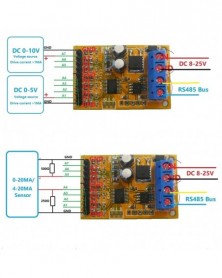
7 csatornás 5V 10V analóg feszültségfelvétel mintavevő RS485 ModBus RTU modul PLC oszcilloszkóphoz ADC 4-20ma érzékelő
282 Ft 576 Ft
Product Name: 7ch 5V 10V Analog Voltage Sampler RS485 ModBus RTU Module for PLC Oscilloscope ADC 4-20ma Sensor
Package inlcuded:
1 x R4AVA07 9V 12V 24V 7 Channel Voltage analog Sampler RS485 module
Description:
1: Operating Voltage : DC 8-25V(DC 9V 12V 15V 24V)
2: Operating Current : 10-15MA
3: MODBUS RTU Command support 03 06 function code
4: The A1/2/3/4 channel voltage measurement range is 0-5V, and the A5/6/7 channel voltage measurement range is 0-10V. The drive capability of the tested voltage source must be greater than 1MA, otherwise the measurement cannot be accurate (MCU IO voltage cannot be measuring)
5: Voltage measurement accuracy of 1% , calibration can be calibrated if the error is greater than 1%
6 :MODBUS commands can be made serial HyperTerminal (serial assistant) OR PLC Enter;
7 :Under the MODBUS command mode, it can support up to 247 devices in parallel
8 :Size: 45 * 30 * 15mm
9 :Weight: 10g
The drive capability of the tested voltage source must be greater than 1MA, otherwise the measurement cannot be accurate (MCU IO voltage cannot be measuring), Recommend to buy a new version. click here : N4AIA04
Instruction manual Please ask us after the purchase
Application
4-20MA/0-20MA Sensor
Voltage analog acquisition
Automated industry PLC
Smart Home,Home Automation ;
Identification system;
RS485 Remote monitoring;
Multimeter voltmeter
Signal generator Oscilloscope
Interface introduction
Wiring diagram
-
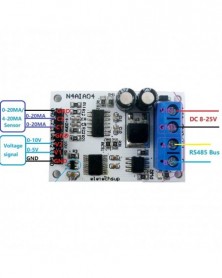
DC 12V 4-20mA 0-5V 0-10V Feszültségjelgyűjtés RS485 Modbus RTU modul PLC áramadó mérőműszerekhez
361 Ft 737 Ft
Product Name: DC 12V 4-20mA 0-5V 0-10V Voltage Signal Acquisition RS485 Modbus RTU Module for PLC Current Transmitter Measuring Instruments
Package inlcuded:
1 x N4AIA04 9V 12V 24V 4 Channel Voltage/Current analog acquisition RS485 module
Description:
1: Operating Voltage : DC 8-25V(DC 9V 12V 15V 24V)
2: Operating Current : 10-14MA
3: MODBUS RTU Command support 03 06 function code
4: V1(CH1) channel voltage measurement range is 0-5V, V2(CH2) channel voltage measurement range is 0-10V, C1/C2(CH3/4) channel current measurement range is 0-20MA/4-20MA
5: Voltage resolution is 0.01V, measurement accuracy is 1% ; current resolution is 0.1MA, measurement accuracy is 1% ; if the error is greater than 1% , it can be calibrated
6 :MODBUS commands can be made serial HyperTerminal (serial assistant) OR PLC Enter;
7 :Under the MODBUS command mode, it can support up to 247 devices in parallel
8 :Size: 45 * 30 * 15mm
9 :Weight: 11 g
Instruction manual Please ask us after the purchase
Application
4-20MA/0-20MA Sensor
Voltage/Current analog acquisition
Automated industry PLC
Smart Home,Home Automation ;
Identification system;
RS485 Remote monitoring;
Multimeter voltmeter
Electronic Measuring Instruments
Interface introduction
Wiring diagram
-
Szín: - DC 5V 8 portos vízszint érzékelő kijelzőkártya folyadékvezérlő érzékelő kapcsoló modul az Arduino UNO
285 Ft 581 Ft
Product Name: DC 5V 8 Port Water Level Detect Display Board Liquid Controller Sensor Switch Module for Arduino UNO MEGA2560 NANO MCU STM32
Package inlcuded:
1x DC 5V 8 Outputs Water Liquid Level Detect Display Board
Products with pump control are highly recommended,Click on the blank: click here
Description:
1 Working voltage: DC 5V
2 Working current 14-18MA
3 One power indicator light, Digital tube shows water level: 0 1 2 3 4 5 6 7 8
4 8 water level output interfaces (low level 0V, high level 3.7V),for MCU IO
5 8 water level sensor interfaces (2P XH2.54)
6 Size: 48mm X 33mm X 12mm
7 Weight: 11.6g(With Pin),9.2g(No Pin)
Note:
1 Package does not contain probe (wire).2P Male XH2.54mm Pitch Wire Cable can be used as a probe,which can be purchased separately or prepared by yourself.
2 For safety, use an DC power supply with good isolation
Application
for Arduino UNO MEGA2560 NANO
Home water tower automatic water supply system
Aquarium Fish tank Water Changer System
Fill the water tower automatically
Automatic pumping from water tower
Conductive liquid automatic control
Automatic feeding system for poultry and livestock
Farm automatic water supply system
And other occasions that require automatic water supply and water exchange.
Solenoid valve water pump motor automatic control
Interface description:
VCC :Power of positive(DC 5V )
GND :Power of negative(DC 5V -)
O1 O2 O3...O8 : water level output interfaces (2.54MM Pin;low level 0V, high level 3.7V)
Leve1Leve2...Leve8 : water level sensor interfaces (2P XH2.54)
Wiring diagram:
Make the probe(Need to be purchased separately):
1 Prepare 2PCS(or more) XH2.54MM wires
(You can prepare this kind of wire by yourself, or buy it from our shop)
2 Multiple wires can be spliced to lengthen the probe length.
(Please do waterproof treatment at the splicing.)
3 Please cut the female interface short and keep a distance of 5-10MM
(This prevents water droplets from sticking to the probe. )
-
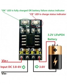
Szín: - Dedikált 3,2 V-os LiFePO4 akkumulátortöltő modul 3,6 V 1A CV/CC túlfeszültség védelemmel, automatikus
191 Ft 390 FtProduct Name: Dedicated 3.2V LiFePO4 Battery Charger Module 3.6V 1A CV/ CC wtih Overvoltage Protection Automatic Recharge Low-Power Sleep Mod
Packing list:
1 PCS 1A 3.2V/3.6V 1S LiFePO4 Battery Dedicated charging module
Description:
Complete Charge Management for Single Cell LiFePO4 Battery
Power supply voltage DC 3.8-6V,Charging output voltage DC 3.6V;
The maximum charge current / output current is 1A, but you can change the current by changing the value of the R1 resistor.
Precharge Conditioning for Reviving Deeply Discharged Cells and Minimizing Heat Dissipation During Initial Stage of Charge
Constant-Current/Constant-Voltage/Constant-Temperature Operation with Thermal Regulation to Maximize Charge Rate Without Risk of Overheating
Automatic Low-Power Sleep Mode When Input Supply Voltage is Removed
C/10 Charge Termination
Automatic Recharge
Battery Temperature Sensing
Battery Overvoltage Protection
Led indicator : ''CR'' LED is charge status indicator
''OK'' LED is fully charged OR Constant voltage mode;
Operating Ambient Temperature-40℃ to +85℃
Size 18mm x 10.16mm x 2.7mm
Weight : 0.9g(With Pin),0.6g(No Pin)
If you need a chip brochure please contact me
Applications:
Car battery charging
Children's toy car, toy airplane
Solar battery charging
Mobile Loadspeaker
Electric Bicycle Charger
UPS Uninterruptible power supply
Portable Industrial and Medical Equipment
Standalone Battery Chargers
Hand-held Equipment
Battery-Backup Systems
Portable Industrial and Medical Equipment
Miner's lamp
LiFePO4 battery applications
The charging current can be changed by changing the value of resistor R1
0805 1% SMD resistor is recommended
-
Szín: - 1-8s 1,2V-9,6V NiMH NiCd újratölthető akkumulátortöltő töltő modul kártya bemenet DC 5V
204 Ft 416 Ft
Product Name: 1-8s 1.2V-9.6V NiMH NiCd Rechargeable Battery Charger Charging Module Board Input DC 5V
Packing list:
1 PCS 1-8 cell NiCd/NiMH batteries Charger Module
(Please choose the parameters you need when purchasing)
Description:
1-Cell(1S) Version:
Input voltage : DC 4.5V-5.5V(Recommend DC 5V)
Charging voltage about : 1.35V-1.7V
Charging current about : 231mA-240mA
2-Cell(2S) Version:
Input voltage : DC 4.5V-5.5V(Recommend DC 5V)
Charging voltage about : 2.7V-3.4V
Charging current about :230mA-240mA
3-Cell(3S) Version:
Input voltage : DC 4.5V-5.5V(Recommend DC 5V)
Charging voltage about : 4.05V-5.1V
Charging current about : 230mA-240mA
4-Cell(4S) Version:
Input voltage : DC 4.5V-5.5V(Recommend DC 5V)
Charging voltage about : 5.7V-6.8V
Charging current about : 230mA-240mA
5-Cell(5S) Version:
Input voltage : DC 4.5V-5.5V(Recommend DC 5V)
Charging voltage about : 6.75V-8.5V
Charging current about : 230mA-240mA
6-Cell(6S) Version:
Input voltage : DC 4.5V-5.5V(Recommend DC 5V)
Charging voltage about : 8.1V-10.2V
Charging current about : 230mA-240mA
7-Cell(7S) Version:
Input voltage : DC 4.5V-5.5V(Recommend DC 5V)
Charging voltage about : 9.45V-11.9V
Charging current about : 190mA-210mA
8-Cell(8S) Version:
Input voltage : DC 4.5V-5.5V(Recommend DC 5V)
Charging voltage about : 10.8V-13.6V
Charging current about : 190mA-210mA
USB power protection
Short circuit protection and zero volt battery activation
Battery protection
Operating ambient temperature : -40° to 85°
Storage temperature : -65° to 125°
Size 30mm x 15mm x 4mm
Weight : 1.5g
Note: The output voltage cannot be measured with a multimeter without a battery. But can be observed with an oscilloscope.
Tip: If your battery is 1-3Cell, please choose a high current version: NIMHCRTA
Applications:
kids toys car
Digital Cameras
Solar charging
Bluetooth Applications
Audio equipment
Digital Camera
Electronic Dictionary
Portable Devices
Mobile power, UPS
1-8Cell Nickel Metal Hydride Battery Charger
1-8Cell NiCd Battery Charger
USB power protection:
When charging multiple batteries, the USB power supply needs to supply a large current. In order to ensure that no USB power is damaged, the NIUP11TA adds USB power protection. When the USB power supply voltage is pulled down to a certain threshold, reduce the charging current to protect the USB power supply. When the USB power supply voltage rises, adjust the charging current to the maximum value.
Short circuit protection and zero volt battery activation:
NIUP11TA can intelligently detect whether the output is short-circuited and indicate an error. The NIUP11TA allows long-term shorts in the output without damaging any circuitry and USB power, and the output is shorted and maintains low power consumption.
The NIUP11TA has a zero-volt battery activation function that determines a zero-volt battery when the short-circuit is detected for the first time after power-on. The horse activates the zero-volt battery, and the zero-volt battery activates and enters the normal charging process. If the zero volt battery is not activated, it will be judged to be a short circuit and the indicator light will start flashing.
Battery protection:
1) If the battery voltage is higher than 1.35V, the battery is considered to be close to full capacity. After plugging in, it will not be charged, and the indicator light will be extinguished to prevent the battery capacity from dropping due to the memory effect of the nickel-cadmium battery.
2) After the battery is connected, the number of battery packs will be judged. If the voltage is not within the corresponding range, charging will not be performed.
Charging process:
1) Battery insertion detection
When the charger is powered up, it will automatically detect the presence or absence of battery insertion. After detecting the zero-volt battery, it will be activated automatically. When the short-circuit is detected, an error will be indicated. If the number of battery packs is not matched with the circuit, an error will be reported. After the correct battery pack is inserted, normal charging will be performed.
2) Pre-charge
If the battery pack connected to the battery pack is less than 1V, it indicates that the battery is discharged too much. It needs to be activated after a small current is activated to prevent damage to the battery. Pre-charging requires a current of 100 mA and a fast charge when the single cell voltage is greater than 1V.
3) Fast charging
If the battery pack connected to the battery pack is already greater than 1V, it indicates that the battery has passed the precharge threshold and can be quickly charged. Fast charging requires current to be controlled at 250mA. The fast charging process should periodically detect the battery voltage and charging current, and detect the battery voltage -v or 0△V, and jump to make up the charging.
4) make up the charge
Fast charging has been used to charge the battery voltage to 1.3V or higher with a large current. If fast charging is used, the temperature of the battery will rise rapidly. It needs to be changed to a smaller current to make up the charge. At this time, the current is controlled at 200mA. Make up the charging time for 20 minutes, and then jump to trickle charging after the end of the charge.
5) trickle charging
In order to make up for the self-discharge of the battery, it will enter the trickle charge after the end of charging. The trickle charge current is 40mA. After entering the trickle charge, the indicator light has been extinguished. When the user removes the battery, it will enter the next charge cycle.
6) Battery take-out detection
When charging is entered, the system will continue to take the battery removal test. After detecting that the battery is removed, it will enter the next charging cycle. -
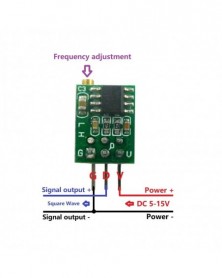
Szín: - 1Hz-6Khz Állítható jelgenerátor Square Wave generátor Modul Arduino Smart Car NE555
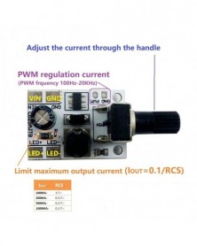
144 Ft 293 FtProduct Name: 1Hz-6Khz Adjustable signal generator Square Wave generator Module Arduino Smart Car NE555
Package inlcuded:
1 x NE555 Frequency Adjustable signal generator
Function Description:
1: Output terminal of the output square wave signal, the amplitude is approximately equal to input voltage.
2: Output duty cycle is not adjustable, basic stability of duty cycle of the output signal in the process of adjusting the frequency (50% -65% ).
3: Frequency through built-in multi-turn potentiometer adjustment, adjustment range: L version is 0.8Hz-60Hz;H Verson is 50Hz-6kHz
4: 3P 2.54mm Pin header
Power:
Supply Voltage DC 5V-15V , No-load current is about 3mA.
Output drive current:
The output circuit is capable of sinking or sourcing current up to 200 mA. Operation is specified for supplies of
5 V to 15 V. With a 5-V supply, output levels are compatible with TTL inputs.
Uses:
Used as signal source in the circuit;
Method of use:
1. Input power then work ;
2. Terminated with a power supply filter capacitor 0.1uf to be more stable.
3. Clockwise adjustment potentiometer, frequency increases, adjustment potentiometer counterclockwise, frequency decreases.
4: Size: 14* 10.5 * 7.4mm(Very small)
5: Weight: 1.4g
Note:
1. Above parameters are measured at 5V, may be different in other voltage.
2. This product is not a sophisticated circuit, not suitable for high precision.
-
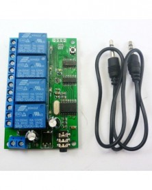
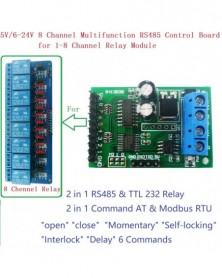
Szín: - 8CH DC 5V 12V 24V RS485 RS232 (TTL) Modbus RTU vezérlőmodul UART relé kapcsolókártyához PLC
318 Ft 648 Ft
Product Name: 8CH DC 5V 12V 24V RS485 RS232 (TTL) Modbus RTU Control Module UART for Relay Switch Board PLC
Package inlcuded:
1 x 5V/6-24V 8 Channel Multifunction RS485 Control Board for 1-8 CH Relay Module
Description:
1: Operating Voltage : DC 5V(5V Version) / DC 6-24V(6-24 Version)
2: Operating Current : 10-15MA
3: ''open'' ''close'' ''Momentary'' ''Self-locking'' ''Interlock'' ''Delay'' 6 Commands
4: Two instruction-control mode : AT command and MODBUS command
5: Under the AT command ,the maximum delay is 9999 seconds
Under the MODBUS command ,the maximum delay is 255 seconds
6 AT commands can be made serial HyperTerminal (serial assistant) Enter;
MODBUS commands can be made serial HyperTerminal (serial assistant) OR ''Modbus Poll'' Enter;
7 Under the MODBUS command mode, it can support up to 247 devices in parallel
8 With RS485 and RS232 (TTL) dual bus interface
9 Output control pins 8, 5V TTL level, low level (default) / high level output
10 Size: 45 * 30 * 15mm
11 Weight: 10g
Instruction manual Please ask us after the purchase
Application
Automated industry PLC
Relay Module
Smart Home,Home Automation ;
Identification system;
Motor FW & BW;
CCTV Camera PTZ Control;
Security system;
LED dot matrix screen;
RS485 remote control;
Command mode selection :( figure above) M0 disconnect is MODBUS command mode. M0 Connect is AT command mode.
Output level selection : ( figure above) M1 disconnect is Low level output. M1 Connect is Hight level output
Slave ID: Different ''Sliver ID'' can be set by command, the maximum number is 247
Under the MODBUS command mode,the slave ID must be correct
command Description, Please refer to '' 8 Channel Multifunction RS485 Module commamd''
Typical applications:
1 AT command mode (M0 Connect), in this mode can be through the serial HyperTerminal (serial assistant) enter a simple AT command control relay. AT command mode time up to 9999 seconds
2 MODBUS command mode (M0 disconnect), you can control a variety of ways: Serial Hyper Terminal Control (need to manually add the CRC), Modbus Poll software control (software automatically add the CRC), PLC or MCU process control
It can control 1-8 channels 5V/6V/9V/12V/24V Relay Module
With RS485 interface and RS232 (TTL) interface
Version identification:
The 6-24V version comes with a 78M05 chip, and the back of the PCB board is labeled 12/24V.
The 5V version does not have a 78M05 chip, and the back of the PCB board is labeled as 5V.
Test Software(We offer a demo video):
Serial HyperTerminal:
Modbus Poll
-
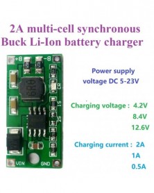
Szín: - DC 5-23V - 4,2V 8,4V 12,6V 1S 2S 3S többcellás Li-Ion lítium akkumulátortöltő szoláris töltéshez Hordozható
306 Ft 625 FtProduct Name: DC 5-23V to 4.2V 8.4V 12.6V 1S 2S 3S Multi-Cell Li-Ion Lithium Battery Charger for Solar charging Portable device
Packing list:
1 PCS 0.5A/1A/2A1/2/3-S synchronous Buck Li-Ion battery charger
(Please choose the parameters you need when purchasing)
Description:
1-Cell(1S) 4.2V Version:
Input voltage : DC 4.5V-23V(Recommend DC 5V/6V/9V/12V/15V)
Charging voltage : 4.2V
Charging current : 1A/2A(Please choose the parameters you need when purchasing)
2-Cell(2S) 8.4V Version:
Input voltage : DC 10-23V(Recommend DC 12V/14.8V/15V/18V)
Charging voltage : 8.4V
Charging current : 0.5A/1A(Please choose the parameters you need when purchasing)
3-Cell(3S) 12.6V Version:
Input voltage : DC 14.8-23V(Recommend DC 14.8V/15V/18V)
Charging voltage : 12.6V
Charging current : 0.5A/1A(Please choose the parameters you need when purchasing)
Led indicator :
Bright: Charging Off: full Blinking: almost full; If the charging current is too large (or the battery capacity is small), it will quickly enter the flashing state, and the charging current should be reduced.
Operating ambient temperature : -40° to 85°
Storage temperature : -65° to 125°
Size : 30*15*5.5mm
Weight : 2g
Applications:
Cellular Telephones,
PDA, MP3 Players, MP4 Players
Digital Cameras
Bluetooth Applications
Solar charging
Game Players
Notebook
li-on Lithium Battery 18650
Mobile phone
Solar charging
MP3/MP4 player
Audio equipment
Portable Devices
-
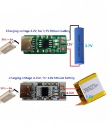
Szín: - 1S Type-C – 4,2 V 4,35 V Step-down Buck LiPo Polymer Li-Ion töltő 3,7 V 3,8 V 18650 lítium akkumulátorhoz
95 Ft 193 FtProduct Name: 1S Type-C To 4.2V 4.35V Step-down Buck LiPo Polymer Li-Ion Charger for 3.7V 3.8V 18650 Lithium Battery
Packing list:
1 PCS 1A DC 5V to 4.2V/4.35V Li-ion Li-Po Lithium Battery Charger
Description:
Type-C Charger for Lithium Ion cell phone battery
Power supply: DC 5V/>=1A
Charging voltage: 4.2V/4.35V
Protection of battery cell reverse connection
Charging current :1A
Complete linear Charger in SOP8 Package for single Cell Lithium-Ion Batteries.
Constant-Current/Constant-Voltage operation with thermal regulation to maximize Rate Without risk of overheating
Preset 4.2V (4.34V) charge voltage with ±1% accuracy
Automatic Recharge
Two Status Indication for Charge status, no battery and battery failure indicators
C/10 charge termination
55μA supply current in shutdown
2.9V trickle current charge threshold
Soft-Start limits inrush current
Led indicator : ''CR'' LED is charge status indicator
''OK'' LED is fully charged OR Constant voltage mode;
Operating Ambient Temperature-40℃ to +85℃
Size : 26mm x 12mm x 4.5mm
Weight : 1.5g
If you need a chip brochure please contact me
The charging current can be changed by changing the value of resistor R1
0805 1% SMD resistor is recommended
-
2 az 1-ben Auto Boost-Buck 1-6V–5V DC DC átalakító modul Arduino DUE YUN Pro mini MEGA2560 Raspberry pi 3-hoz
197 Ft 402 FtBelow item is powered by Canton-Power Ltd .
Product Name: 2 in 1 Auto Boost-Buck 1-6V to 5V DC DC Converter module for Arduiuo DUE YUN Pro mini MEGA2560 raspberry pi 3
Packing list:
1 PCS DD0603SB_5V 1-6V TO 5V( -5% ) DC DC Boost-Buck Converter Module
Description:
Input voltage DC 1 ~ 6V, output DC 5V( -5% )
The maximum input voltage can not exceed 6.5V
Auto Buck-Boost Converter Module working frequency 1MHZ.efficiency 61% -85% .
Operating temperature range : -25~ 85 Degrees Celsius
Storage temperature range : -45~ 125 Degrees Celsius
Size : 22mm x 15mm x 5.7mm(Very small)
Weight : 2.3g(Very light)
Applications
Battery powered equipment
FPGA CPLD MCU Breadboard Power Supply
DUE YUN Pro mini MEGA2560
electrical tools
Small power motors
18650 Solar Charger li lion battery
Camera, Video camera
Toy car
power bank
LED Lighting
Wireless communication equipment
Audio equipment
Attention :
This is a DC-DC voltage converter module,Must be noted when using:
1 Input voltage can not be greater than the maximum input range
2 Output power can not be greater than the maximum load for a long time
3 Input power must be greater than the output power, because the power consumption of the module itself
Q & A:
Q : Why output voltage is less than the nominal voltage
A : Input power supply power is too low.Test the input voltage with a multimeter,a t this time of the input voltage is very low
-
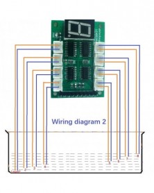
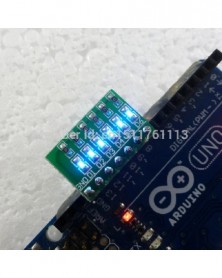
Rapid Prototyping LED Breadboard Arduino UNO MEGA2560 MEGA NANO PRO MINI MCU LoL Shiel málna pi Atmega328 ATMEGA16U2
150 Ft 307 FtProduct Name:Rapid Prototyping LED Breadboard for Ardiuno UNO MEGA2560 MEGA NANO PRO MINI MCU LoL Shiel raspberry pi Atmega328 ATMEGA16U2
No matter how many pieces you buy the board, you only need to pay 1 piece Shipping costs
Module No.: TB311
Packing list:
1 pcs 6 bit Blue LED's Board(Does not include ARDIUNO UNO R3);
Description:
Can be inserted directly into Ardiuno uno mega2560,Ideal for linking up to your Ardiuno UNO Mini Nano Mega2560 etc,or others MCU ( AVR STM32 ARM7 ARM9 ARM10 PIC AT89C51 STC MSP430 FPGA CPLD etc.)
1 6 bit Blue Common Cathode LEDS.
2 7 PIN OUT 2.54mm
3 1K ohm Limiting resistor
4 Power Supply Voltage: 3.3-12V;
5 Size: 17.78MM x 11.43MM.
Circuit schematics :
Connection with Ardiuno(Only 6 bit LED's Board ,Does not include ARDIUNO UNO R3) :
Circuit schematics :
Ardiuno uno/mega2560 Code
//******************************************************//
/*
Ardiuno_6led
This example code is in the public domain.
*/
// give it a name:
int D1 = 13;
int D2 = 12;
int D3 = 11;
int D4 = 10;
int D5 = 9;
int D6 = 8;
// the setup routine runs once when you press reset:
void setup() {
// initialize the digital pin as an output.
pinMode(D1, OUTPUT);
pinMode(D2, OUTPUT);
pinMode(D3, OUTPUT);
pinMode(D4, OUTPUT);
pinMode(D5, OUTPUT);
pinMode(D6, OUTPUT);
}
// the loop routine runs over and over again forever:
void loop() {
digitalWrite(D1, HIGH); // turn the LED on (HIGH is the voltage level)
delay(200); // wait for a 200 Millisecond
digitalWrite(D1, LOW); // turn the LED off by making the voltage LOW
digitalWrite(D2, HIGH); // turn the LED on (HIGH is the voltage level)
delay(200); // wait for a Millisecond
digitalWrite(D2, LOW); // turn the LED off by making the voltage LOW
digitalWrite(D3, HIGH); // turn the LED on (HIGH is the voltage level)
delay(200); // wait for a Millisecond
digitalWrite(D3, LOW); // turn the LED off by making the voltage LOW
digitalWrite(D4, HIGH); // turn the LED on (HIGH is the voltage level)
delay(200); // wait for a Millisecond
digitalWrite(D4, LOW); // turn the LED off by making the voltage LOW
digitalWrite(D5, HIGH); // turn the LED on (HIGH is the voltage level)
delay(200); // wait for a Millisecond
digitalWrite(D5, LOW); // turn the LED off by making the voltage LOW
digitalWrite(D6, HIGH); // turn the LED on (HIGH is the voltage level)
delay(200); // wait for a Millisecond
digitalWrite(D6, LOW); // turn the LED off by making the voltage LOW
}
//******************************************************// -
Szín: - 5V-24 1-4 csatornás flip-flop relémodul Bistabil önzáró trigger időkapcsoló PLC kártya be/kikapcsolása
208 Ft 425 FtProduct Name:5V-24 1-4CH Flip-Flop Relay Module Bistable Self-locking Trigger Time Switch Turn on/off PLC Board
Packing list:
1 pcs 1/2/4 Channel DC 5V/12V Bistable Self-locking Relay Module
Please select the version you need
Description:
1 Channel DC 5V Self-locking Relay Module(version 1) :
Working voltage: DC 5V
Working current: 62-70MA
Standby current: 0.1mA
Load current: AC 250V / 10A, DC 30V / 10A
Trigger mode: Low pulse trigger
Size: 35mm * 16mm * 18.5mm (L * W * H), Very small size
Weight: 12.5 g
1 Channel DC 12V Self-locking Relay Module(version 2) :
Working voltage: DC 6-24V(Recommended DC 9V 12V)
Working current: 61-70MA
Standby current: 0.12mA
Load current : AC 250V/10A, DC 30V/10A
Trigger mode: Low pulse trigger
Size: 48mm * 16mm * 18.5mm (L * W * H), Very small size
Weight: 14 g
2 Channel DC 5V Self-locking Relay Module(version 3) :
Working voltage: DC 5V
Working current: 1 relay 70MA;2 relay 140MA;
Standby current: 0.2mA
Load current: AC 250V / 10A, DC 30V / 10A
Trigger mode: Low pulse trigger
Size: 36mm * 32.3mm * 18.5mm (L * W * H)
Weight: 24.5 g
2 Channel DC 12V Self-locking Relay Module(version 4) :
Working voltage: DC 6-24V(Recommended DC 9V 12V)
Working current: 1 relay 70MA;2 relay 140MA;
Standby current: 0.25mA
Load current : AC 250V/10A, DC 30V/10A
Trigger mode: Low pulse trigger
Size: 48mm * 32.3mm * 18.5mm (L * W * H), Very small size
Weight: 27.6 g
4 Channel DC 5V Self-locking Relay Module(version 5) :
Working voltage: DC 5V
Working current: 1 relay 70MA;2 relay 140MA;3 relay 210MA;4 relay 280MA
Standby current: 0.41mA
Load current: AC 250V / 10A, DC 30V / 10A
Trigger mode: Low pulse trigger
Size: 65mm * 42mm * 18.5mm (L * W * H)
Weight: 52.4 g
4 Channel DC 12V Self-locking Relay Module(version 6) :
Working voltage: DC 6-24V(Recommended DC 9V 12V 24V)
Working current: 1 relay 37MA;2 relay 73 MA; 3 relay 1 10MA; 4 relay 146 MA
Standby current: 2mA
Load current: AC 250V / 10A, DC 30V / 10A
Trigger mode: Low pulse trigger
Size: 65mm * 47mm * 18.5mm (L * W * H)
Weight: 56.8g
USE 1:
By default, the relay is release, press the trigger button, the relay pull, press again, the relay release, the third press, the relay pull, and so on.
USE 2:
By default, the relay is release, MCU output low-pulse(0.3-1seconds), the relay pull, low-pulse again, the relay release, the third low-pulse, the relay pull, and so on.
Module interface:
1. V: positive power supply (VCC)
2. G: negative power supply (GND)
3. T (T1/T2/T3/T4): Low pulse trigger
Relay outputs:
1. NO: normally open relay interface
2. COM: Common Interface Relays
3. NC: normally closed relay interface
USE : By default, the relay is release, press the trigger button, the relay pull, press again, the relay release, the third press, the relay pull, and so on
Typical applications:
Automotive electronics
Motor/PLC/LED
Smart Home/Home automation
Emergency lighting
MCU development board
Toy car
UNO MEGA2560 raspberry pi
diy electronic kit -
DC 6-24V 20W állítható fényerejű LED meghajtó PWM vezérlő DC-DC fokozatmentes állandó áram átalakító
193 Ft 394 FtProduct Name : DC 6-24V 20W Adjustable Brightness LED Driver PWM Controller DC-DC Step-down Constant Current Converter
Packing list:
1 PCS 20-900MA 6-25V Multifunction Handle adjustment LED driver Module
Description:
6-25V 900mA Step-down High Brightness LED Driver with 5000:1 Dimming
Working voltage : DC 6-25V(Perfect for 6V 9V 12V 18V 24V LED Driver)
Output Current: 20-900MA;By changing the RCS resistance, the maximum current can reach 1200MA
Maximum output power: 20W
Current regulation: 1 through through the handle, 2 through PWM control
Single pin on/off and brightness control using DC voltage or PWM
Up to 1MHz switching frequency
Typical 5% output current accuracy
Inherent open-circuit LED protection
High efficiency (up to 97% )
High-Side Current Sense
Hysteretic Control: No Compensation
Adjustable Constant LED Current
Size : 28 x 20 x 16MM(Handle not included)
Handle Size : Length 13MM,Diameter 6MM
Weight : 5g
Application 1: Wiring in accordance with the following figure, Adjust the current through the handle.
Application 2: Ignore the adjustable resistance, control the output current through the PWM port, the current is 0-900MA adjustable
Application 3 : Add an enable control switch based on application 1.
-
Szín: - 4-20MA/0-5V/0-10V 4 csatornás áram/feszültség analóg adatgyűjtés RS485 Modbus RTU ADC modul
517 Ft 1 056 FtBrand Name : eletechsup
Certification : None
Origin : CN(Origin)
is_customized : Yes
Contact Load : Low Power
Voltage : 12V
Model Number : N43IC04
Protect Feature : Epoxy
Power Source : DC
Usage : General Purpose
Product Name: DC 12V DAC 4-20MA/0-5V/0-10V 4ch Current/Voltage Analog Acquisition RS485 Modbus RTU ADC Module
Package inlcuded:
1 x N43IC04 4ch Current Analog Acquisition RS485 Modbus RTU ADC Module
OR 1 x N43VD04 4ch Voltage Analog Acquisition RS485 Modbus RTU ADC Module
Features:
1: Operating Voltage : DC 8-25V
2: Operating Current : 10-15MA
3: MODBUS RTU Command support 03 06 16 function code
4: The Current measurement range is 0-10mA, 0-20mA and 0-50mA, The Voltage measurement range is 0-5V, 0-10V and 0-20V. depending on the back of the module
5 The current resolution is 0.01 mA and Voltage resolution is 0.01V, with a measurement accuracy of 1% and can be calibrated if the error is greater than 1%
6 :MODBUS commands can be made serial Hyper Terminal (serial assistant) OR PLC Enter;
7 :Under the MODBUS command mode, it can support up to 247 devices in parallel
8 :Size: 45 * 30 * 15mm
9 :Weight: 10 g
Modbus RTU Command Please refer to : ''N43IC04 modbus rtu protocol''
RS485 bus connection method -
Szín: - 10 W 2 csatornás többszörös kapcsolóüzemű tápegység modul 3,3 V 5 V 12 V kettős kimenetű DC DC Step-Down
205 Ft 418 Ft
Product Name : 10W 2 Channels Multiple Switching Power Supply Module 3.3V 5V 12V Dual Output DC DC Step-Down Buck Converter Board
Packing list:
1 PCS 10W 2 Channel Dual output DC DC Buck Converter
Description:
L Version:Input DC 7-30V,Output1 DC 5V/Output2 DC 3.3V
H Version:Input DC 14-30V,Output1 DC 12V/Output2 DC 5V
L Version Maximum Output Current : 5V/1A;3.3V/1A
H Version Maximum Output Current : 12V/0.5A;5V/1A
DC-DC Step-Down Converter module working frequency 550KHz. efficiency is 75-90% .
Quiescent current: about 1MA
Overtemperature shutdown, input under-voltage protection, BS-voltage protection, and short circuit protection.
2.54mm pin pitch, Arduiuo UNO MEGA2560 Breadboard MCU Development Board friendly
Size : 25mm x 21mm x 5.8mm(Small)
Weight : about 3g(Light)
Pin description:
O1 : Output 1 positive
G : Output 1 negative -
I : Input positive
G : Input negative -
O2 : Output 2 positive
G : Output 2 negative -
Attention :
This is a DC-DC voltage converter module,Must be noted when using:
1 Input voltage can not be greater than the maximum input range
2 Output power can not be greater than the maximum load for a long time
3 Input power must be greater than the output power, because the power consumption of the module itself
Applications:
3.3V 5V 12V MCU ARM CPU FPGA/CPLD
12V 5V 3.3V lithium battery-powered systems
Small Motor Toy
WIFI esp8266 HC-12 Bluetooth Module
CCTV camera
Wireless Module:Nrf24l01 CC1101 CC2500 CC2530 Zigbee
Smart home / home automation
Distributed Power Systems
Battery Charger
Pre-Regulator for Linear Regulators
FM radio
Battery powered equipment
Audio amplifier
-
Szín: - 4 csatornás 3,3 V 5 V 12 V 24 V digitális logikai szint átalakító modul PNP/NPN-ről NPN optikai leválasztó
119 Ft 243 FtProduct Name: 4ch 3.3V 5V 12V 24V Digital Logic Level Conversion Module PNP/NPN to NPN Optical Isolation Board for Arduiuo UNO NANO STM32 AVR
Packing included:
1 PCS 4-chanels 3.3V 5V 12V 24V to photoelectric isolation logic level conversion module
Features
1. Multiple usage Used for signal isolation, PLC level conversion, PNP/NPN to PNP signal, signal level voltage conversion, etc.
2. Use original brand new Taiwanese coupler
3. Limit switching frequency up to 10KHZ
4 Arduiuo NANO UNO esp8266 raspberry pi
5. Size:38mm*20mm*5mm
6. Weight:3.9g
Module wiring terminal and definition:
Function Label Instruction
Signal Input 1 The first signal input anode
1- The first signal input cathode
2 The second signal input anode
2- The second signal input cathode
3 The third signal input anode
3- The third signal input cathode
4 The fourth signal input anode
4- The fourth signal input cathode
Power Input VCC DC power anode(*)
GND DC power supply cathode
Signal Output O1 The first signal output
O2 The second signal output
O3 The third signal output
O4 The fourth signal output
(*):The DC power supply is the same as the signal output voltage. For example, if the signal is from 3.3V to 5V, then VCC=5V input.
Schematic diagram of the internal structure of the module:
Module connection diagram:
Common anode signal(NPN) input
Input and output truth table
Signal Input Signal Output
H(High level)5V L(Low level)0V
L(Low level)0V H(High level)24V
Note:In this example, the anode of the signal power supply is DC 5v, and the anode of the module power supply is DC 24V
Common cathode signal input:
Common cathode signal(PNP) input:
Input and output truth table
Signal Input Signal Output
H(High level)5V H(High level)24V
L(Low level)0V L(Low level)0V
Note:In this example,Module power supply is DC 24V
Differential signal input:
Input and output truth table
Signal Input Signal Output
H(High level) H(High level)24V
L(Low level) L(Low level)0V
Note:In this example,Module power supply is DC 24V
-
Szín: - 3,3 V 5 V 8 bites kék/piros közös anódos/katódos LED jelző Modul barkácskészlet Arduino NANO UNO raspberry pi 4
77 Ft 157 FtProduct Name: 3.3V 5V 8 Bit Blue/Red Common anode/cathode LED indicator Module diy kit for Arduiuo NANO UNO raspberry pi 4 nodemcu
Packing list:
1 pcs DC 3-24V 8 Bit Blue/Red Common anode/cathode LED Bar;
Description:
Can be inserted directly into Breadboard,Ideal for linking up to your Arduiuo UNO Mini Nano Mega2560 DUE Breadboard etc,or others MCU ( AVR STM32 ARM7 ARM9 ARM10 ARM11 PIC C8051 STC MSP430 FPGA/CPLD etc.)
DC 3.3V 3.7V 5V 12V 24V 8 Bit Blue/Red Common anode/cathode LED Bar
Color : Blue/Red
Working Voltage : DC 3-24V
Polarity : Common anode/Common cathode
Interface : 2.54MM with PIN/2.54MM no PIN
Size: 22.86 x 14.13 x 2.11 mm
Weight : 1.3g(with Pin),0.75g(no Pin)
Application :
MCU/ARM/FPGA/Atmega328p
PLC Motor
Electronic diy kit
ESP8266/nodemcu
NANO/UNO/MEGA2560/Breadboard
Raspberry pi 4/robot
Circuit schematics :
Connection with UNO
Arduiuo uno/mega2560 Code
//******************************************************//
/*
Arduiuo_8led
This example code is in the public domain.
*/
// give it a name:
int D1 = 9;
int D2 = 8;
int D3 = 7;
int D4 = 6;
int D5 = 5;
int D6 = 4;
int D7 = 3;
int D8 = 2;
// the setup routine runs once when you press reset:
void setup() {
// initialize the digital pin as an output.
pinMode(D1, OUTPUT);
pinMode(D2, OUTPUT);
pinMode(D3, OUTPUT);
pinMode(D4, OUTPUT);
pinMode(D5, OUTPUT);
pinMode(D6, OUTPUT);
pinMode(D7, OUTPUT);
pinMode(D8, OUTPUT);
}
// the loop routine runs over and over again forever:
void loop() {
digitalWrite(D1, HIGH); // turn the LED on (HIGH is the voltage level)
delay(200); // wait for a 200 Millisecond
digitalWrite(D1, LOW); // turn the LED off by making the voltage LOW
digitalWrite(D2, HIGH); // turn the LED on (HIGH is the voltage level)
delay(200); // wait for a Millisecond
digitalWrite(D2, LOW); // turn the LED off by making the voltage LOW
digitalWrite(D3, HIGH); // turn the LED on (HIGH is the voltage level)
delay(200); // wait for a Millisecond
digitalWrite(D3, LOW); // turn the LED off by making the voltage LOW
digitalWrite(D4, HIGH); // turn the LED on (HIGH is the voltage level)
delay(200); // wait for a Millisecond
digitalWrite(D4, LOW); // turn the LED off by making the voltage LOW
digitalWrite(D5, HIGH); // turn the LED on (HIGH is the voltage level)
delay(200); // wait for a Millisecond
digitalWrite(D5, LOW); // turn the LED off by making the voltage LOW
digitalWrite(D6, HIGH); // turn the LED on (HIGH is the voltage level)
delay(200); // wait for a Millisecond
digitalWrite(D6, LOW); // turn the LED off by making the voltage LOW
digitalWrite(D7, HIGH); // turn the LED on (HIGH is the voltage level)
delay(200); // wait for a Millisecond
digitalWrite(D7, LOW); // turn the LED off by making the voltage LOW
digitalWrite(D8, HIGH); // turn the LED on (HIGH is the voltage level)
delay(200); // wait for a Millisecond
digitalWrite(D8, LOW); // turn the LED off by making the voltage LOW
}
//******************************************************// -
SG11A02 1-10 kHz üzemi ciklus és frekvencia állítható PWM négyzethullámú impulzusgenerátor modul NE555 LM358 CD4017 DDS
215 Ft 439 FtProduct Name: 1-10kHz Duty Cycle & Frequency Adjustable PWM Square Wave Pulse Generator Module replace NE555 LM358 CD4017 DDS AD9850 AD9851
Package inlcuded:
1 x 1Hz~10Khz Duty Cycle & Frequency Adjustable signal generator
Description:
VCC : DC 5V(3.8~5.5V) Power supply positive
GND : Power Supply Negative
PWM : 1Hz-10kHz(Accuracy:0.6% ) Square wave output(5V TTL Level,maximum output current 20MA).
PCB size : 19.4*12*6.7mm
Weight : 1.5g
power-down storage parameters
Frequency and Duty Cycle continuously adjustable, Stepping: See the image below
USE:
Short press (less than 2S) : Fine adjustment
Long press (more than 2S) : Quick adjustment
Wiring Diagram:
Size &Weight:
10khz Waveform:
500Hz Waveform:
1Hz Waveform:
-
Szín: - 30-1500MA állítható állandó áramú LED meghajtó DC 3,3V 3,7V 4,2V 5V PWM vezérlőkártya Buck tápmodul
84 Ft 172 FtProduct Name : 30-1500MA Adjustable Constant Current LED Driver DC 3.3V 3.7V 4.2V 5V PWM Control Board Buck Power module
Packing list:
1 PCS 30-1500MA LED Driver Module(with Pin and no Pin optional)
Description:
Working voltage : DC 2.8-6V(Perfect for 3V 3.3V 3.7V 5V 6V LED Driver)
Output Current: 30-1500MA
Maximum output power: 9W
Can drive 1-16pcs 3-6V LEDs (maximum current does not exceed 1.5A)
Current regulation: 1 through adjustable resistance; 2 through PWM control
Chip Temperature Regulation
Over LED Current Protection
Operating Temperature Range
Size : 18mm x 10.3mm x 2.8mm
Weight : with Pin 0.86g,no Pin 0.56g
Application 1: Wiring in accordance with the following figure, use a suitable screwdriver gently and slowly rotate the adjustable resistance.
Application 2: Adjust the adjustable resistance to 0 ohms (or maximize the current according to Application 1) and then use the MCU output PWM signal to control the LED output current
the frequency of the PWM signal should be less than 2KHz
LD06AJSA/B is a current regulation integrated circuit operating from an input voltage of 2.8V to 6V, the constant
output current can be set up to 1.5A with an external resistor. The LD06AJSA/B consists of high precision reference
voltage, amplifier, current mirror, etc. The on-chip power transistor and current sense block greatly reduce the
external component count, which makes the LD06AJSA/B ideal for LED driver.
When the CE pin is high, the input voltage is greater than 2.8V, and is larger than the LED forward voltage plus
the required voltage drop, LD06AJSA/B functions normally to deliver constant current from the LED pin.
The LD06AJSA/B adopts the temperature regulation instead of temperature protection function, the temperature
regulation can make the LED being turned on continuously in case of high ambient temperature or high voltage
drop. When the LD06AJSA/B junction temperature reaches about 135 ° C, the internal temperature regulation block
reduces the LED current so that the junction temperature will not rise any more. This feature allows the users to
maximize the use of the power handling capability of the chip, do not worry about the chip overheating and
damage to the chip or external components.
The LD06AJSA/B also has the chip enable function, which can shutdown the whole chip to limit the current
consumption within 1uA.
The LD06AJSA/B also adopts the over current protection block. When LED current approaches 1.9A(Typical), the
over current protection block begins to function to prevent the LED current from increasing further. -
BE/KI DC-DC fokozó-növelő konverter 3V 3.3V 3.7V 4.2V 5V–12V Feszültségszabályzó WIFI Router PLC RS485 RS232 számára
158 Ft 322 FtBelow item is powered by eletechsup Ltd .
Product Name: ON/OFF DC-DC Step-up Boost Converter 3V 3.3V 3.7V 4.2V 5V to 9V Voltage Regulate for WIFI Router PLC RS485 RS232
Packing list:
1 PCS 6W DDEN12MA_12V 2.6V-5.5V TO 12V DC-DC Boost Converter Module
Description:
Input voltage DC 2.6 ~ 5.5V,output DC 12V±3%
Maximum output : 12V/550MA(See the table below for details)
DC DC Boost Converter Module working frequency 1MHZ.
Up to 94% Efficiency (usually is 75% -91% )
Quiescent current : Turn on output 210uA,Turn off output 5uA.
Operating temperature range : -40~ 85 Degrees Celsius
Storage temperature range : -65~ 150 Degrees Celsius
2.54mm pin pitch,for Arduino UNO MEGA2560 MCU Development Board Breadboard friendly.
Size(Does not include pin) : 20 x 15 x 6MM
Weight : 1.8g
Protection :
Over current protection(OCP)
Over voltage protection(OVP)
Short circuit protection(SCP)
Over temperature protection(OTP)
Pin description:
Pin description:
Vi : Input positive( )
En : Output enable, Connect to GND turn on output, Not connected(Or Connect to Vi) turn off output
This pin can also be controlled by MCU, low level turn on output, high level Turn off output
G : Input and Output negative(GND/-)
Vo: Output positive( )
Applications
Battery powered equipment
Instrumentation, multimeter
Small power motors
PTZ Camera webcam
IP Camera
Toy car boat
Model aircraft
power bank
LED Lighting
WIFI Router
PLC RS485 devices
Attention :
This is a DC-DC voltage converter module,Must be noted when using:
1 Input voltage can not be greater than the maximum input range
2 Output power can not be greater than the maximum load for a long time
3 Input power must be greater than the output power, because the power consumption of the module itself
Q & A:
Q : Why output voltage is less than the nominal voltage
A : Input power supply power is too low.Test the input voltage with a multimeter,a t this time of the input voltage is very low
-
3 V 3,3 V 3,7 V 4,5 V – 5 V DC DC átalakító Lépésnövelő Árammód PWM feszültségátalakító modul
197 Ft 402 FtProduct Name : 3V 3.3V 3.7V 4.5V to 5V DC DC Converter Step-Up Boost Current Mode PWM Voltage Transformation Module
Packing list:
1 PCS 5W 3V-5V TO 5V Boost Step-UP Voltage Regulator Module
Description:
Input voltage 2.6~6V, output 5V (deviation -6% )
Maximum input current : 1.2A
Long-term work Current : 1A
Conversion efficiency : 79-91%
Start Voltage 2.6V, Output Current 50MA
INPUT 2.8V 1A; OUTPUT 5V 290MA
INPUT 3V 1A; OUTPUT 5V 480MA
INPUT 3.3V 1A; OUTPUT 5V 590MA
INPUT 3.7V 1A; OUTPUT 5V 650MA
INPUT 4.5V 1A; OUTPUT 5V 790MA
DC-DC Boost module working frequency 1.0MHZ.
Operating ambient temperature : -40~ 85 Degrees Celsius
2.54mm pin pitch,Arduiuo UNO DUE Breadboard FPGA/CPLD Development Board friendly.
Over Temperature Protection
Over Voltage Protection
Excluding Pin Size 20.5mm x 10.16mm x 5.6mm(Very small)
Weight : about 1.4g(Very light)
Applications:
MCU Development Board,FPGA/CPLD UNO MEGA2560 DUE 8051 AVR C8051 etc
RS485 PLC Modbus RTU
VCR
PDA
LED Lighting
5V Relay board
Wireless communication equipment
315M 433M Wireless remote controller
Attention :
This is a DC-DC voltage converter module,Must be noted when using:
1 Input voltage can not be greater than the maximum input range
2 Output power can not be greater than the maximum load for a long time
3 Input power must be greater than the output power, because the power consumption of the module itself
Q & A:
Q : Why output voltage is less than the nominal voltage
A : Input power supply power is too low.Test the input voltage with a multimeter, a t this time of the input voltage is very low -
Szín: - 72W 1-3A DC 6V 9V 12V 24V 36V 48V Állítható állandó áramú LED meghajtó modul MCU IO PWM vezérlőkártya
318 Ft 648 FtProduct Name : 72W 1-3A DC 6V 9V 12V 24V 36V 48V Adjustable Constant Current LED Driver Module MCU IO PWM Controller Board
Packing list:
1 PCS 6V 9V 12V 24V 36V 48V 1-3AHigh-powerMultifunction LED driver Module
Description:
DC 6-50V 1-3A Step-down High Brightness LED Driver with 5000:1 Dimming
Working voltage : L Version DC 6-16V, H Version DC 8-50V(Perfect for 6V 9V 12V 18V 24V 36V 48V LED Driver)
Output Current: 1A/2A/3A;By changing the RCS resistance, the maximum current can reach 4A
Maximum output power: 72W(36V/2A)
Current regulation: 1 through adjustable resistance; 2 through PWM control
Single pin on/off and brightness control using MCU IO or PWM
Up to 1MHz switching frequency
Typical 5% output current accuracy
Inherent open-circuit LED protection
High efficiency (up to 97% )
High-Side Current Sense
Over temperature drop current function
Adjustable Constant LED Current
Size : 45mm x 21mm x 16mm
Weight : 11g(No terminal),14g(with terminal)
Note : Different versions have different operating voltages and maximum output currents, please see the table below:
Application 1: Wiring in accordance with the following figure, use a suitable screwdriver gently and slowly rotate the adjustable resistance.
Application 2: Ignore the adjustable resistance, control the output current through the PWM port, the current is 0-900MA adjustable
Application 3 : Add an enable control switch based on application 1.
-
DC 3-12V 433Mhz ASK OOK EV1527 Kódolt tanulási kód Adómodul otthoni betörésbiztonsági riasztórendszerhez Vezeték
370 Ft 755 Ft
Product Name : DC 5V 12V 1 CH 433Mhz ASK OOK PT2262 SC2262 Encoded Transmitter Module for GSM SMS Home Burglar Security Alarm System
Packing list:
1 PCS 433Mhz ASK OOK EV1527 Encoded Transmitter Module
Note:
This is our company wireless control receivers Accessories
If used in other applications, please read the the parameters carefully before purchase
Technical Data :
Power supply : DC 3-12V(Recommendation : 5V 12V)
Operating current: 9 mA;
Oscillation mode: SAW resonator;
Modulation mode: ASK/OOK;
Operating frequency : 433.92MHZ ;
Encoding IC : EV1527 OR compatiable IC;
Output power : 60MW;
RC Resistance : 300K;
Pin Description:
Typical applications: