Kereskedelmi, irodai és ipari
-
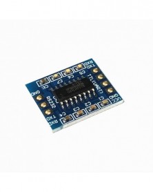
DC 12V időkésleltetési relé NE555 időrelé árnyékolás időzítő relé időzítő vezérlő kapcsoló autó relék
142 Ft 296 FtVehicle equipment-delay to prevent car ignition, prevention of
high sudden current to burn components and devices.
This is a 5V / 12V Conduction delay relay module
This is a brand new and high quality delay turn-on module.
the use of high-performance timing CPU design.
the power indicator LED and switch trigger timing indication
LEDs;
The output can be connected to AC 250V 10A DC 30V 10A
load;
There is the chronopotentiometry regulation time, adjustable
from 0 to 10 seconds by default, or by changing the
capacitance adjustment time longer
Specification:
1.Module based on: NE555 chip.
2.Delay modue:delay connect module
3.Input voltage: DC 12V
4.Control voltage: AC 0~250V / max. 10A, DC 0~30V / max. 10A the operating voltage: 12 volts DC; (otherwise 5V optional)
5.Max. load: 2200W
Main Chip (NE555) Characteristics:
1.Timing from microseconds to long hours
2.Simple circuit design
3.Precision Pulse Generation / Timing,
4.Adjustable Duty Cycle -
L9110S DC léptetőmotor meghajtó kártya H Bridge L9110
57 Ft 119 FtDescription:
1 L9110S-chip motor drive
2 Module supply voltage: 2.5-12V
3 Suitable Motor range: between motor operating voltage 2.5v-12V, the maximum operating current of 0.8A, the current smart car voltage and current market are within this range
4 Drive two DC motors, or a 4-wire 2-phase stepping motor.
5 PCB board size: 2.8cm * 2.1cm ultra-small size, suitable for assembly
6 Is provided with a fixed mounting holes, diameter: 3mm
modules Interfaces:
6P black bent pin description:
1 VCC external voltage 2.5V-12V
2 GND External GND
3 AIA external microcontroller IO port
4 AIB external microcontroller IO port
5 BIA external microcontroller IO port
6 BIB external microcontroller IO port
4P green terminal:
1 OA1 OB1 contact DC 2-pin, non-directional
2 OA2 OB2 contact DC 2-pin, non-directional
Use:
ON VCC, GND module power indicator light
AIA input high, AIB input low, [OA1 OB1] motor is transferred;
AIA input low, AIB input high, [OA1 OB1] motor reversal;
BIA input high, BIB input low,] [OA2 OB2 motor is transferred;
BIA input low, BIB input high,] [OA2 OB2 motor reversal;
Package includes:
1 x L9110S H-bridge Stepper Motor Dual DC motor Driver Controller Board -
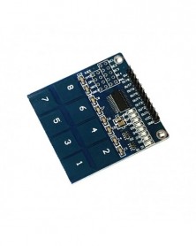
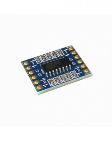
TTP226 8 csatornás digitális érintésérzékelő modul kapacitív érintéskapcsoló
127 Ft 265 FtTTP226 8 Channel Digital Touch Sensor Module Capacitive Touch Switch
Product information
Description:
1, onboard TTP226 capacitive 8 keys touch sensor IC
2, onboard 8 channel level status indicator
3, working voltage: 2.4V-5.5V
4, the module can set the output mode, the key output mode, the maximum output time and fast / low power selection
5, PCB board size: 47.5 (mm) x46 (mm)
Package including:
1pc x TTP226 8 Channel Digital Touch Sensor Module Capacitive Touch Switch
TTP226 8 Channel Digital Touch Sensor Module Capacitive Touch Switch
Product information
Description:
1, onboard TTP226 capacitive 8 keys touch sensor IC
2, onboard 8 channel level status indicator
3, working voltage: 2.4V-5.5V
4, the module can set the output mode, the key output mode, the maximum output time and fast / low power selection
5, PCB board size: 47.5 (mm) x46 (mm)
Package including:
1pc x TTP226 8 Channel Digital Touch Sensor Module Capacitive Touch Switch -
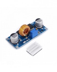
5A XL4015 DC-DC Step Down állítható tápegység modul LED lítium töltő
141 Ft 293 FtModule performance and features:
Module Properties: non-isolated step-down module (BUCK)
Input voltage: 4-38V (input please try not to exceed 38V)
Output voltage: 1.25-36V continuously adjustable
Output Current: 0-5A, recommended in 4.5A.
Output Power: 75W recommendations in the use of more than 50W, please add heat sink.
Operating temperature: -40 to 85 degrees
Operating frequency: 180KHz
Conversion efficiency: up to 96% (efficiency of input and output voltage, current, pressure related)
Load regulation: S (I) ≤0.8%
Voltage Regulation: S (u) ≤0.8%
Power Indicator: YES
Short circuit protection: YES (limit current 8A)
Overtemperature protection: (automatically shut off the output after overtemperature)
Input Reverse Polarity Protection: None (if necessary please enter the string into the high current diode)
Installation: 2 3mm screws
Connection: Welding, V-IN is the input, V-OUT output
Module dimensions: length 54mm width 23mm height 18mm
-
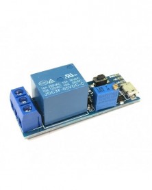
5V-30V Micro USB tápellátás állítható késleltetésű relé időzítő vezérlő modul trigger késleltetés kapcsoló
93 Ft 193 FtWide voltage 5V-30V trigger delay relay module timer module delay switch Wide voltage 5V-30V trigger delay relay module timer module delay on delay switch
Module highlights:
The time can be adjusted by the potentiometer to meet your most occasions. With MicroUSB 5.0V power input, it is very convenient to use. 5--30V power supply voltage. External trigger and on-board key trigger. With relay pull-in indicator. Strong anti-interference ability, the relay will not malfunction under various interference, suitable for industrial control.
Module characteristics:
1. Working voltage: any voltage between 5-30V wide, MicroUSB and welding terminal power supply interface 2. Working mode: After supplying power to the module, the state of the output terminal of the module is: normally open (NO) is disconnected from the common terminal (COM), and normally closed (NC) is connected with the common terminal (COM). Give a low-pulse signal at the external trigger terminal (TRIG) or touch the trigger button, the relay sucks and the work indicator lights up. At this time, the status of the relay output terminal is: normally open (NO) and the common terminal (COM) are conducting, The normally closed (NC) is disconnected from the common terminal (COM). After 0-24 seconds (this time can be adjusted according to your needs), the relay is disconnected, and the relay returns to the state before triggering. 3. The time can be adjusted by the potentiometer. The default is 0-24 seconds. If it takes longer, you can replace the larger capacitor (C2) or potentiometer by yourself. Delay time formula: T = 1.1RC. For example: if the capacitance is 22uf and the resistance is 1M, then T = 1.1 * 0.000022 * 1000000 = 24.2 seconds. 4. With relay pull-in indicator. 5. The module can control: 10A 250VAC (AC), 10A 30VDC (DC) load. 6. With relay continuous current protection. 7. The signal end of the module is designed with a pull-up and filter circuit, which has strong anti-interference ability and is suitable for industrial control. Many manufacturers have added optocouplers for isolation, but the module is not isolated from the ground of the trigger signal, which does not provide anti-interference effect. After testing, it is found that the stability of the trigger terminal can be improved to resist interference. No matter the module is in an electromagnetic interference environment or when the module is powered on and off, the relay will not malfunction. 8. Size: 5.4 * 1.9 * 1.8cm (length * width * height) 9. Weight: 16g
Applications:
1. Anti-theft alarm delay, building sound and light control light switch, etc. 2. On-time delay of on-board equipment prevents excessive current from burning the vehicle equipment when the vehicle is on fire. 3. Sequential start-up is required to prevent multiple devices from starting at the same time when the current is too large to burn down the appliance.
-
F233-01 Négyirányú infravörös nyomkövetés / 4 csatornás nyomkövető modul / távvezeték / akadálykerülő / autó
147 Ft 307 FtFour-way infrared tracing / 4 channel tracking module / transmission line modules / obstacle avoidance / car / robot sensors
Specifications:
Working voltage: DC 3.3V-5V
Working current: try to choose more than 1A power supply
Working temperature: - 10oC - 50oC
Mounting aperture: M3 screws
Detection range: 1mm to 60 CM adjustable, the closer the performance more stable, white reflects the farthest distance.
Size: in the control panel of 42mm * 38mm * 12mm (length * width * height)
Small forward 25mm * 12mm * 12mm (length * width * height)
Output interface: 6 wire interface (1234 to 4 signal output ends, positive power, - for the negative power is ground)
The output signal: TTL level (can be directly connected to I/0 microcontroller, infrared light reflected back to the sensor induction, the red indicator light, output low level; no infrared light, the indicator light does not shine, the output high.)
Applications:
A Smart car or a robot hunt ( including the black and white lines ) , walking along the black line path , also known as tracing .
(2) smart car to avoid the cliff , anti- fall.
3 smart car to avoid obstacles
-
1db NodeMcu Node MCU Base ESP8266 Tesztelő Barkács kenyérlap alapteszter NodeMcu V3-hoz
197 Ft 411 FtDescription:
1.This is a breadboard for the LOLIN NodeMCU Development Board ESP8266-12E for IDE see other listing
2.Please note this has a pin spacing of 28MM between the rows unlike the unit made by DOIT witch is 23 MM
3.This is compatible with the LOLIN NodeMCU not the DOIT device
Package Included
1x Nodemcu Base Plate
-
MCP2551 nagy sebességű CAN protokoll vezérlő busz interfész modul
73 Ft 153 FtMCP2551 CAN protocol controller high-speed bus interface module
MCP2551 is a fault-tolerant, high-speed CAN devices can be used as CAN protocol controller and the physical bus interface. MCP2551 provides differential receive capability to the CAN protocol controller, which is fully in line with ISO-11898 standards, including energy 24V requirements.
Typically, each node on the CAN system must have a device, the digital signal is converted into CAN controller generates a signal for bus transport. It also provides high voltage spikes between CAN controller and CAN bus joined the buffer, these high-pressure spikes may be generated by an external device.
Support 1MB / S's run rate.
· Meet the ISO-11898 standard physical layer requirements.
· Suitable for 12V and 24V systems. Slope external control, reduce RFI.
Automatic detection TXD input ground fault.
· Power-on reset and voltage brown-out protection.
· Unpowered node or Brown will not affect CAN bus.
· Low current standby operation.
* Up to 112 nodes can be connected. -
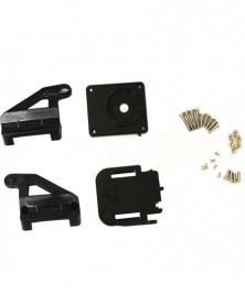
FPV Aerial Camera Mikro nylon műanyag kéttengelyes szervo gimbal mini konzol
81 Ft 168 FtRemarks: This gimbal is in bulk and needs to be assembled with servos and cameras
The two-axis plastic gimbal weighs 20 grams and is suitable for 9g-12g servos. It has beautiful appearance, precise production, no hypocrisy and no shaking, and has a steering gear wire winding clip.
The whole picture is 4 pieces of plastic parts including screws, not including the servos and cameras in the picture
Please also note: At present, this type of gimbal is only suitable for 28*28 camera modules, not suitable for 32 or 38 cameras -
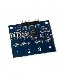
ÚJ 4 csatornás digitális érintésérzékelő kapacitív kapcsolómodul gomb TTP224
124 Ft 258 FtDescription
Specification:
1. Onboard TTP224 campacitive 4 key touch induction IC.
2. Onboard the 4 way level indicator.
3. Operating voltage:2.4V-5.5V.
4. Module can set the output mode,output longest time,and fast/low power selection.
5. PCB board size:35(mm)×29(mm).
Package included:
1 × TTP224 4-way capacitive touch switch digital touch sensor module switch button. -
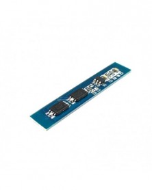
2S 5A 18650 lítium akkumulátor töltésvédő kártya modul töltő 7,4 V 8,4 V pad modul nagy áramerősség védelem
84 Ft 176 FtFeatures:
1) high-precision voltage detection circuit;
2) terminal device of the charger using high voltage;
3) Built-in three-stage overcurrent detection circuit (overcurrent 1, overcurrent protection 2, or short-circuit current);
4) MOS transistor can control charge and discharge;
5) Low standby power consumption.
Parameter:
Above charge voltage: 4.25-4.35v ± 05 v
Beyond dishcarge voltage: 2.5-3.0v ± 05 v
Continuous DC Max: 5A
Max peak current: 7A
Operating temperature: -40 --- 50
Storage temperature: -40- 80
Small current: less than 5uA
Life cycle: more than 50000 hours
Resistance: less than 300mΩ
Short cut protection: Protective, charge able to repair
Size: 38 * 8 * 2mm
2 S BMS Cnnection instruction:
B positive battery connect;
B-Negative battery connection;
MB Connect the point between battery1 & battery 2;
P Positive charge / discharge;
P-Negative charge / discharge.
Package Includes:
1*2S 5A Li-ion Lithium Battery 18650 Charger Protection Board Pad Module 7.4V 8.4V
-
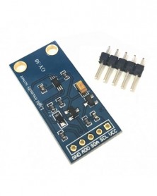
GY-30 A modul BH1750FVI digitális optikai fényintenzitás-érzékelője
129 Ft 269 FtDigital light intensity detection Model: GY-302
Dimensions: 13.9mm X 18.5mm
Original BH1750FVI chip using ROHM
Power supply :3-5v
Data range 0-65535
Sensor built 16bitAD converter
Direct digital output, omitting complex calculations, calibration is omitted
Does not distinguish between ambient light
Spectral characteristics close to visual sensitivity
Brightness can be a wide range of high-precision measurement lux
Digital Light intensity detection module: GY-30
The ROHM genuine BH1750FVI chip
Power supply :3-5v
Illumination range :0-65535 lx
The sensor built 16bitAD converter
Direct digital output, complex calculation is omitted, omitting calibration
Does not distinguish between ambient light
Close to the visual sensitivity of the spectral characteristics
1 lux high-precision measurement of a wide range of brightness -
Szín: 1EXAR (egyes 20x16 mm - RS232 SP3232 TTL - RS232 modul RS232 - TTL kefevonal soros port modul
63 Ft 131 FtConnection instructions:
Note: TTL and RS232 must be connected to TXD and RXD. RXD to TXD. Cross-matching
TTL (UART) end:
VCC: Connect to DC 3V-5.5V
GND: Connect to GND
TXD: Connect to the TTL end RXD of the external device
RXD: Connect to the TTL terminal TXD of the external device
RS232 terminal:
RXD: Connect to the external device RS232 terminal TXD
TXD: Connect to the RS232 terminal RXD of the external device
GND: Connect to GND -
Szín: 3EXAR (egyes 51x15 mm - RS232 SP3232 TTL - RS232 modul RS232 - TTL kefevonal soros port modul
109 Ft 227 FtConnection instructions:
Note: TTL and RS232 must be connected to TXD and RXD. RXD to TXD. Cross-matching
TTL (UART) end:
VCC: Connect to DC 3V-5.5V
GND: Connect to GND
TXD: Connect to the TTL end RXD of the external device
RXD: Connect to the TTL terminal TXD of the external device
RS232 terminal:
RXD: Connect to the external device RS232 terminal TXD
TXD: Connect to the RS232 terminal RXD of the external device
GND: Connect to GND -
Szín: 5EXARdouble20,7x16mm - RS232 SP3232 TTL - RS232 modul RS232 - TTL kefevonal soros port modul
69 Ft 144 FtConnection instructions:
Note: TTL and RS232 must be connected to TXD and RXD. RXD to TXD. Cross-matching
TTL (UART) end:
VCC: Connect to DC 3V-5.5V
GND: Connect to GND
TXD: Connect to the TTL end RXD of the external device
RXD: Connect to the TTL terminal TXD of the external device
RS232 terminal:
RXD: Connect to the external device RS232 terminal TXD
TXD: Connect to the RS232 terminal RXD of the external device
GND: Connect to GND -
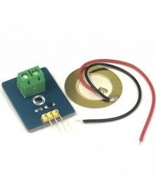
Dob szimuláló piezoelektromos érzékelő analóg kerámia vibrációs érzékelő modul piezoelektromos
92 Ft 192 FtIntroduction
WAVGAT analog piezoelectric ceramic vibration sensor based on piezoelectric ceramic chip analog vibration makes use of the anti-transformation process of piezoelectric ceramic making the electric signals vibrate. When piezoelectric ceramic chip is vibrating, the sensor signal terminal will generate electrical signals. The sensor can be used with Arduino dedicated sensor shield, and Arduino analog port can perceive weak vibration signals, so that it can work out the interactive works related to vibration, such as electronic drum interactive work. Please connect analog voltage ceramic vibration sensor to the Arduino UNO controller's analog port A0 in accordance with the procedure, then observe the output value of serial port when the vibration degree is different, it can realize interactive works related to the vibration.
Specification
Supply Voltage: 3.3V to 5V
Working Current :<1mA
Working Temperature Range:-10°~+70°
Output Signal:analog signal
Sample Code
void setup()
{
Serial.begin(9600); //Open the serial to set the baud rate for 9600bps
}
void loop()
{
int val;
val=analogRead(0); //Connect the analog piezoelectric ceramic vibration sensor to analog interface 0
Serial.print("Vibration is ");
Serial.println(val,DEC);//Print the analog value read via serial port
delay(100);
}
Result
Wiring as the above diagram and burning the code, after power-on, open the serial monitor, then set the baud rate for 9600 and vibrate ceramic chip, as the graph shown below. -
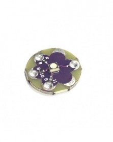
LilyPad TriColor LED RGB fényforrás modul
90 Ft 187 FtLilyPad Tri-Color LED
\\
Description:Blink any color you need! Use the Tri-Color LED board as a simple indicator, or by pulsing the red, green, and blue channels, you can create any color. Very bright output. This is a common anode design-to turn on a channel you simply need to ground one of the R/G/B pins to illuminate that channel.
LilyPad is a wearable technology developed by Leah Buechley and cooperatively designed by Leah and SparkFun. Each LilyPad was creatively designed to have large connecting pads to allow them to be sewn into clothing. Various input, output, power, and sensor boards are available. They 're even washable!
\\
Note:A portion of this sale is given back to Dr. Leah Buechley for continued development and education of e-textiles.
\\
================================================= ================================================= =================
\\
\\
\\ -
PWM egyenáramú motor fordulatszám vezérlő automatikus szabályozó vezérlő DC 1,8 V - 3 V 5 V 6 V 12 V 15 V 2 A alacsony
138 Ft 288 FtFeature: This product is suitable for the speed regulation of DC motor, fan, fish tank oxygen pump and other products in DC 1.8V--15V. The DC motor speed controller uses pulse width modulation (PWM) DC voltage to control the speed of the DC motor. The duty cycle can be fully adjusted from 0% to 100% . The motor speed controller is with a self-recovery fuse 2A and a Power LED light It can easily provide a continuous current of 2A to your DC motor or other DC load. Input supply voltage: 1.8V-15VDC
Specification: Motor type: DC Motor Model number: LWC-L-010 Input voltage: DC 1.8V-3V-5V-6V-12V Output voltage: linear under load Output current: 0-2A Sustained current: 2A Speed control type: current control Speed adjustment way: potentiometer (linear) Speed range: 0-100% Connection types: fence type terminal Module size: 32 mm * 32 mm * 15 mm Package Included: 1 * PWM DC Motor Controller Module with Potentiometer Switch DC 1.8 -12V 2A -
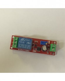
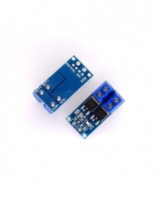
Szín: 12V - Normál esetben nyitott trigger késleltető kapcsoló relé 5V9V12V késleltető áramkör időzítő
127 Ft 264 Ft1. Product application:
This module is a delay module that uses key switches, touch switches, micro switches, and other normally open self-reset switches to trigger. It can also be triggered by normally open sensors, such as vibration sensors, reed switches, etc. Can form a vibration alarm sensing device. Mainly used in machinery and equipment, automation equipment modification, PLC industrial control, vibration alarm settings, robots, intelligent products.
two. product description:
1. Using advanced high-quality timing chip control, accurate timing;
2. Use high-power relay to control the load, up to 10A;
3. It has a protection diode to prevent the power connection from being reversed to better protect the module;
4. The trigger terminal adopts optocoupler isolation, which has strong interference and interference ability and avoids false triggering;
5. With 8 optional time ranges, the shortest is 0.1 second, and the longest is 1 hour;
6. The delay has a potentiometer adjustment, the clockwise adjustment time will be longer;
7. With power indication and delay switch indication;
8. The relay output has normally open and normally closed interfaces.
three. Features:
Normally open trigger function introduction: Before the module is triggered, the circuit at the trigger end is in an open state. If there is an instantaneous switch closure or continuous closure, the module can be triggered to delay and the relay is closed.
1. Connect the 5V DC power supply to the module, and wait for the trigger terminal to see if there is a switch close trigger signal
2. When the trigger terminal of the module senses that the switch is closed, the module will start the delay function, and the relay will be closed at the same time, and the delay will end, and the relay will open;
3. When the module is triggered in the delay, if a trigger signal is received again, the module will re-time and automatically trigger the last time until the delay is over.
The trigger terminal can support the trigger delay of the following sensors:
1. Touch the switch
2. Micro switch
3. Self-reset switch
4. Normally open type vibration sensor
5. Normally open reed switch
6. Normally open door magnetic sensor
7. Tilt sensor switch
8. Water level switch
four. Electrical parameters:
Power supply voltage: 5V, 12VDC
Quiescent current: 4.8mA Maximum power consumption: 70mA
Trigger time: 1ms or more is enough
Relay load capacity: 250V 10A AC 30V 10A DC (In actual applications, it is best to reduce the power by half, which is beneficial to prolong the service life of the product)
Relay life: 100,000 times (maximum power)
Fives. Selection method of delay time range:
Switch S1.S2.S4 to different positions to select different time ranges, and the potentiometer is to adjust the time within the corresponding range -
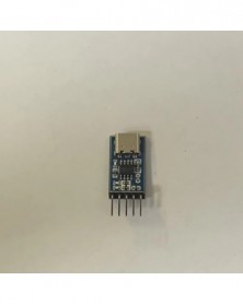
TYPE-C USB-TTL soros port CH340N modul CH340 DC 5V/3.3V Upgrade MCU Download Brush Line
81 Ft 168 FtProduct description:
This product is a Type-C to TTL serial port module, using CH340N USB bus adapter chip, with 3 indicator lights on the board, 1 is the power indicator, and the other 2 are communication indicators.
Because there is no serial port on our current computer, we generally use a USB to serial port module, with only one purpose, to map the computer's USB port to a serial port.
Size:25x14x5mm
Material:PCB
colour:Blue
Package Contents:
1 x Module
Only the above package content, other products are not included.
Note: Light shooting and different displays may cause the color of the item in the picture a little different from the real thing. The measurement allowed error is /- 1-3cm. -
KY-005 3 tűs infravörös emissziós érzékelő modul a barkács indítókészlethez KY005
77 Ft 161 FtInfrared emission control, also known as infrared emitting diodes, diode class belongs. It can be directly converted into electrical energy near infrared
Light (black light), and can radiate out of the light emitting device is mainly used in various photoelectric switches and remote control transmitter circuit. Infrared emission control structure, principles and common light-emitting diodes are similar, but different semiconductor materials used. Typically use gallium arsenide infrared emitting diode (GaAs), gallium aluminum arsenic (GaAlAs) and other materials, the use of transparent or light blue, black resin package.
Firing distance, launch angle (15 degrees, 30 degrees, 45 degrees, 60 degrees, 90 degrees, 120 degrees, 180 degrees), the light intensity emitted wavelength. The above physical parameters, need to understand its electrical performance parameters: the diameter of the common market, 3mm, 5mm for low-power infrared emission control, 8mm, 10mm for medium power and high-power launch tube. Forward voltage low-power transmitting tubes: 1.1-1.5V, current 20ma, the power of the forward voltage: 1.4-1.65V 50-100ma, high-power launch tubes for the forward voltage:. 1.5-1.9V200-350ma Yu Electronic make 1-10W power infrared emission control can be applied to infrared surveillance lighting. -
4 tűs KY-026 IR lángérzékelő tűzérzékelő modul érzékeli a barkácskészlet infravörös vevőjét
111 Ft 231 FtDescription:
High sensitivity IR receiver
Extremely sensitive to wave between 760-1100nm
Power supply indicator lamp
Comparator output indicator lamp
AO, real-time thermister voltage signal output
DO, high / low electric level signal output
Analog quantity output
Threshold rollover electric level output
Threshold adjusted by potentiometer
Detection Angle Range: About 60 degrees
Power Supply: 0-15 V DC
Hole Inner Diameter: Approx. 3mm
Size (L x W): Approx. 36 x 16mm -
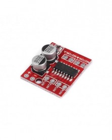
Egyenáramú motor meghajtó modul irányváltó PWM sebesség, kettős H híd léptetőmotor mini Victory L298N
87 Ft 181 FtDual DC motor driver module, forward or reverse, PWM speed control, dual H-bridge stepper motor, mini, beyond L298N
Description: motor drive module is ideal for use in battery-powered smart car, toy cars, robots. Supply voltage 2V ~ 10V, can drive two DC motors or a 4-wire 2-phase stepper motors ,can achieve forward rotation or reverse rotation, it is possible to adjust the rotation speed. Each can provide continuous current of 1.5A, peak current up to 2.5A, thermal protection and can be automatically restored.
Product Highlights:
1. Use of imported original chip, built-in low on-resistance MOS switch, minimal heat, no heat sink, small size, low power consumption, is ideal for battery powered.
(L298N internal transistor switch, low efficiency, high fever, need to add heat sink, bulky, L298N very easy to burn)
2. Dual 1.5A * 2, the peak current to be 2.5A, built-in thermal protection circuit, do not be afraid motor stall burned, automatic recovery after the temperature dropped.
3. Small size, light weight, 0 standby current, is the ideal choice for your car model.
[Attach function diagram]
INx connected to the MCU I / O port, MOTOR-A and MOTOR-B is connected to the motor.
DC motor drive logic truth table:
Product parameters:
1. Dual H-bridge motor driver, can drive two DC motors or a 4-wire two-phase stepper motor;
2. The module supply voltage 2V-10V;
3. Signal input voltage 1.8-7V;
4. Single Operating current 1.5A, peak current up to 2.5A, low standby current (less than 0.1uA);
5. Built-in common conduction circuit, when the input pin is left floating, the motor does not malfunction;
6. Built-in thermal protection circuit with hysteresis effects (TSD), without worrying about motor stall;
7. Product Size: 24.7 * 21 * 5mm (length, width, height), ultra-small size;
8. The mounting hole diameter: 2 mm.
9. Weight: 5g
Precautions:
1. Power positive and negative reversed will certainly cause damage to the circuit.
2. Output is shorted to ground or output short circuit, and the motor stall, the chip will heat protection, but in the near or exceeding 10V voltage and peak current is greater than 2.5A situation can also cause chip burned. -
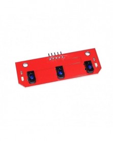
3-utas nyomkövető modul / vadászmodulok / Robottartozékokhoz drop
121 Ft 252 FtProduct Description:
1,3 road tracking sensors, the robot making necessary
2, the use of infrared light detection, anti-jamming capability, using CTRT5000 sensor, adjustable sensitivity, stable performance
3, the operating voltage 5V, output low white lines
4, exquisite workmanship, with lights, a fixed bolt hole for easy installation -
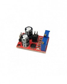
5V-12V NE555 impulzusfrekvenciás munkaciklus, állítható modul négyzethullámú jelgenerátor 10kHz -200kHz
94 Ft 196 Ftthe scope of this module:
1 is used as a square wave signal generator generates a square wave signal used for experimental development. 2 to drive a stepper motor for generating a square wave drive signal. 3 adjustable pulse generated for use by MCU. 4 adjustable pulse generation, control circuitry associated.
Description:
1, Size: 3.1CM * 2.2CM 1, the main chip: NE555; 2, Input voltage: 5V-15VDC. 5V power supply, the output current can 15MA around; 12V power supply, the output current can 35MA around; 3, the input current: 100MA 4, the output amplitude: 4.2V V-PP to 11.4V V-PP. (Different depending on the input voltage, the output amplitude will be different) 5, the maximum output current: 15MA (5V power supply, V-PP greater than 50% ), 35MA (12V power supply, V-PP greater than 50% )
Advantages:
1, the output with LED indication, there is no output straightforward (low LED volume, high LED off frequency is relatively low, the LED flashes); 2, the output level selectable frequency range, the output frequency is more continuously adjustable; LF file: 1Hz ~ 50Hz IF file: 50Hz ~ 1kHz High-frequency file: 1KHz ~ 10kHz HF file: 10kHz ~ 200kHz 3, the output duty cycle can fine-tune, duty cycle and frequency is not separately adjustable, adjusting the duty cycle will change the frequency 4, the output frequency is adjustable; Period T = 0.7 (RA 2 RB) C RA, RB is 0-10K adjustable; Low profile when C = 0.001UF; IF stalls C = 0.1UF; High-frequency file C = 1UF; HF stalls C = 100UF, so the frequency of the waveform buyers can own calculations.;
Package Included:
1 x Module
-
5 DB Esővízszint-érzékelő Vízcseppek észlelési mélysége
136 Ft 283 FtRain Water Level Sensor Module Detection Liquid Surface Depth Height For Arduino
Product Details:
Water Level Sensor
Condition: New
Operating voltage: DC3-5V
Operating current: less than 20mA
Sensor Type: Analog
Detection Area: 40mmx16mm
Production process: FR4 double-sided HASL
Operating temperature:10-30
Humidity: 10% -90% non-condensing
Product Dimensions: 62mm x 20mm x 8mm
Color is red, shown as pictures
PLS NOTE that due to lighting effects, monitor's brightness / contrast settings etc, there could be some slight differences in the color tone of the pictures and the actual item!
Package Included:
1 x Water Level Sensor -
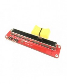
Csúsztassa potenciométer 10K lineáris modul kettős kimenet
141 Ft 293 FtFeatures:
100% Brand new and high quality!
USES the high quality slide appliances, stable and reliable performance
Dual analog output, 0 - VCC analog voltage signal
Specifications:
Size: 90 * 20 mm
Color: Red
Voltage: 3.3 V, 5 V
Port: analog
Resistance: 10 k
Platform: For Arduino, For MCU, For ARM, and other single chip micro
Package Included:
1PCS *Slide Potentiometer 10K Linear Module Dual Output for Arduino AVR Electronic Block -
Hall érzékelő modul 3144E 4 tűs Hall kapcsoló sebesség mágneses kapcsolók sebességszámláló érzékelő modul
81 Ft 169 Ft100% brand new and high quality
Features:
When the sensor senses a magnetic field, the digital output is low and the signal light is on; if no magnetic field is sensed, the digital output is high and the signal is not lit.
With power indicator and signal indicator.
Small volume, high sensitivity, fast response speed, good temperature performance, high accuracy, high reliability.
LM393 comparator output, good waveform, strong driving ability.
It can be used for motor speed measurement, position detection, etc.
Output Mode: digital switching output (0 and 1) AO port is not valid.
Specification:
Material: FR4 Electronic components
Operating Voltage: 3.3-5 V
Size: app.3.1X1.4cm/1.2X0.55cm(LxW)
Quantity: 1 Pc
Note:
No retail package
Transition: 1cm=10mm=0.39inch
Please allow 0-1cm error due to manual measurement, please make sure you do not mind before you bid.
Due to the difference between different monitors, the picture may not reflect the actual color of the item. Thank you!
Package includes:
1 x Hall Effect Sensor -
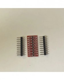
I2C IIC 8 csatornás logikai szintátalakító modul kétirányú modul 3,3 V-ról 5 V-ra
81 Ft 168 FtDescription: If you've ever tried to connect a 3.3V device to a 5V system, you know what a challenge can be. A bidirectional logic level translator is a small device that safely steps down a 5V signal to 3.3V while boosting 3.3V to 5V. This level shifter is also available for 2.8V and 1.8V devices. What sets this logic level translator apart from our previous versions is that you can successfully set high and low voltages and safely raise and lower them on the same channel. Each level shifter has the ability to convert 4 pins on the high side to 4 pins on the low side, with two inputs and two outputs for each side
Level shifters are very easy to use. The board needs to be powered by the two voltage sources (high voltage and low voltage) used by the system. High voltage (eg 5V) to "HV" pin, low voltage (eg 3.3V) to "LV", ground from system to "GND" pin
Compatible with 5-3V systems
VIN is connected to 5V system power supply
5A to 5V system
5B is connected to 5V system
GND connects to 5V system GND
3V3 connects to 3V system power supply
3A connection to 3V system
3B connection to 3V system
GND connects to 3V system GND
Dimensions: 28×19mm / 1.1×0.74 inches -
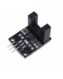
Nyaláb fotoelektromos érzékelő Elektromos számlálómodul LM393 motorszámláló sebesség érzékelő modul tesztmodul
91 Ft 189 Ftsize:32mm(L)*11mm(W)*20mm(H)
Main chip:LM393,Correlation type infrared head
Working voltage:DC 5V
Features:
1,signal output indication
2,sigle-way signal output
3,output effective signal is low level
4,sensitivity non-adjustable
5,can be used to Workpiece count and Motor speed detect
6,Circuit board outputs switch quantity -
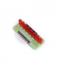
8 utas vízlámpa lámpás LED mikrokontroller modul Intelligens járműtartozékok
91 Ft 189 Ft8 way water lamp, horse lantern module
Singlechip expansion module
Finished plate
Specifications:
1.PCB size: 47mm (long) *19mm (wide) *1.6mm (thick)
2.LED:5mm red red emitting diode
3. rejection 470 ohm or 1000 ohm -
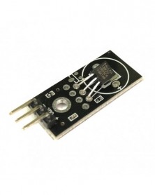
DS18B20 egybuszos digitális hőmérséklet-érzékelő modul
99 Ft 207 FtFirst, the parameters:
1. Size: 28.2mm (length) * 13.1mm (width) * 5.5mm (height)
2. Weight: 5g
3. Operating voltage: 3V - 5.5V
4. Sensor Model: DS18B20
5. The signal output format: digital signal
6. Temperature measurement range: -55 'C --125 ‘C
7. Measuring accuracy: 0.5 'C
8. Resolution: 9--12 bits
9. with fixing screw holes for easy installation and fixation. Aperture 2.6mm
Second, the wiring instructions:
" ": Positive power supply
"-": Negative one
"Out": connected microcontroller IO port -
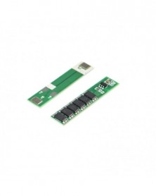
Az egysoros 186503.7 v lítium akkumulátorvédő lemez 6MOS egyre többször ponthegeszthető a túltöltés és a túltöltés
96 Ft 199 FtSingle-string 186503.7 v Lithium Battery Protection Plate 6MOS can be spot-welded more and more, to prevent over-charge and over-discharge -
Szín: Type-c 1M fekete - Mini Micro Print Type-C USB-KÁBEL 50CM 1M
92 Ft 192 FtMini Micro Print Type-C USB CABLE 50CM 1M -
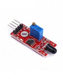
IR lángérzékelő modul érzékelő Smartsense hőmérsékletérzékeléshez Alkalmas
81 Ft 169 FtUses:
Various flame, fire detection
Module Features:
One can detect a flame or in a 760 nanometer wavelength of ~ 1100 nm range of the light, lighter flame test distance of 80cm, for the greater flame, the farther the distance test
2, the detection angle of 60 degrees or so, particularly sensitive to the flame spectrum
3, sensitivity adjustable (shown in blue digital potentiometer adjustment)
4, the comparator output signal clean, good waveform, driving ability, more than 15mA
5, with adjustable precision potentiometer sensitivity adjustment
6, the working voltage of 3.3V-5V
7, the output format: digital switching outputs (0 and 1)
8, a fixed bolt holes for easy installation
9, small plates PCB Size: 3.2cm x 1.4cm
10, using a wide voltage LM393 comparator
Module for use:
1, the flame sensor flame most sensitive to ordinary light is also a rection, generally used as a flame alarm purposes.
2, a small plate output interface can be directly connected to the microcontroller IO port
3, with the flame sensor to maintain a certain distance, so as not to damage the sensor temperature, the flame of a lighter test distance 80cm, for the greater flame, the farther the distance test
-
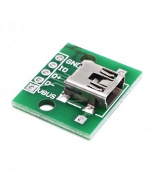
USB-DIP csatlakozóaljzat MINI5P javítás 2,54 mm-es egyenes dugós hegesztett adapterkártyához (U8)
67 Ft 139 FtUSB to DIP female header MINI5P patch to 2.54mm straight plug welded adapter board (U8) -
Reed érzékelő modul magnetron modul reed kapcsoló mágneses kapcsoló
87 Ft 182 FtUses:
PBX, photocopiers, washing machines, refrigerators , cameras, Xiaoduwangui , door , window magnetic , electromagnetic relays, electronic weighing, level meter , gas meter , water meter , etc. have been well used.
Module Features :
1, imported normally open reed
2 , the comparator output signal is clean, good waveform , driving ability , more than 15mA.
3, the working voltage of 3.3V-5V
4, the output format : digital switching outputs ( 0 and 1 )
5 , a fixed bolt holes for easy installation
6, small PCB board size : 3.2cm x 1.4cm
7 , using a wide voltage LM393 comparator
Reed features:
Reed is a dry reed pipe for short, is a kind of passive electronic switching element contacts , with a simple structure , small size easy to control , etc., which is generally a sealed enclosure glass tube are installed there are two elastic spring plate of iron , also called rhodium metal filling with inert gas . Normally, the two reed glass tube made of special materials are separated . When a magnetic substance near the glass tube under the action of the magnetic field lines of the two reed tube is magnetized to attract each other in contact spring will pull together to make a circuit node connected to the communication . External magnetic disappear after two reeds are separated because of their flexibility , the line also disconnected. Therefore, as a signal to control the use of a magnetic field line switching devices , reed can be used as a sensor for counting , limit , etc. ( in the security system is mainly used for door sensor , magnetic window production ) , but also is widely used in a variety of communications devices. In practice, this is usually controlled by the permanent magnet is turned on or not two pieces of metal , it is also called " magnetron ."
Module for use:
1 Reed needs and with the use of magnets in magnetic induction to a certain time, will form a conduction state , the module output low, when there is no magnetic force , was disconnected state , the output high , reed and sensing distance beyond the magnet within 1.5cm of insensitivity or may no trigger phenomenon ;
2 module DO output can be MCU I / O port is directly connected through the microcontroller can detect dry reed pipe trigger state ;
3 output and relay module DO IN terminal connected to form high-power reed switches, high voltage direct control . -
Mini DC-DC Boost Step Up Converter 3V 3.2V 3.3V 3.7V 5V 9V – 12V Feszültségszabályozó PCB kártya modul 5V/8V/9V
62 Ft 129 FtSpecification:
1.Input voltage: DC 2.5V-Vout
2.Fixed Output voltage: 12V
Can set the DC 5V/8V/9V output
Output capacity:
input 3.7V battery, output 5V 1A, 8V 0.5A, 9V 0.45A, 12V 0.3A
Input 5V, output 8V 0.7A, 9V 0.7A, 12V 0.5A -
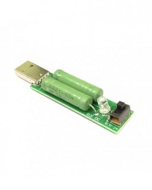
USB mini kisülési terhelési ellenállás 2A/1A Kapcsolóval 1A zöld led, 2A piros led
102 Ft 213 Ft1. Using toggle switch, two-color work lights: 1A and 2A can be directly switched current discharge. When the switch 1A work, the green light. When the switch 2A work, the red light.
2. Large area copper, increase the cooling holes: the back of the expansion of the copper area, increase the cooling hole. Enhanced cooling function.
3. True 5 ohm winding resistance: The discharge resistance uses a customizable true 5 ohm winding resistance (higher cost), resulting in more accurate test results (closer to 2A and 1A).
Tutorial
Function switch: When your power supply maximum output is 1A, then switch to 1A file to test; when your power output is 2A or above, switch to 2A file for testing.
Judgment criteria: Insert the USB output port of the detected USB power supply / mobile power supply, 1A work, the green light. When the switch 2A work, the red light.
Note:
1. The work of the loader, winding resistance due to high current, will inevitably produce very, very high temperature, so in use, and just use a short time, So as not to be burned! Do not allow flammable materials to touch the tester to avoid fire! In short the use of the process must be highly vigilant!
2. Taking into account the resistance around the particularity of the initial use of electricity for some time after the emergence of a small white smoke and odor phenomenon is due to external paint also contains a very small amount of water, power high-temperature heating, water evaporation white smoke, Paint by high-temperature baking smell, after the use of a period of time completely disappeared. This phenomenon will appear, is a normal situation, do not worry about damage to the load tester, please rest assured that use. -
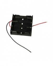
A négy 5-ös elemtartó dobozba 4 darab 5-ös elem fér bele Barkácsolás játéktartozékok vastag dróttal
71 Ft 147 FtBattery box four AA batteries can hold 4 AA batteries with thick wires
about 14.43 grams
Size: 62.94*57.54*15.79 -
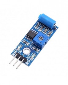
SW-420 normál zárt rezgésérzékelő modul riasztórendszerhez Barkácsolás intelligens jármű robot helikopter helikopter
83 Ft 172 FtSW-420 Motion Sensor Module
Condition: New
Purpose:
Used to trigger the effect of various vibration, theft alarm, intelligent car, earthquake alarm, motorcycle alarm, etc.
This module is compared with the normally open type vibration sensor module, vibration trigger for longer periods of time, can drive the relay module
Module features:
2. The comparator output, signal clean, good waveform, driving ability is strong, for more than 15 ma
3. The working voltage of 3.3V to 5V
4. Output form: digital switch output (0 and 1)
5. Has a fixed bolt hole, convenient installation
6. Small board PCB size: 3.2cm x 1.4cm
7. Use the LM393 wide voltage comparator
Module directions for use:
1. Product no vibration, vibration switch is closed on state, the output terminal output low level, the green light is lit
2. Product vibration, the vibration switch instantaneous disconnection, output the output high level, the green light is not bright
3. Output can be directly connected to microcontroller, through single chip microcomputer to detect the high and low level, thus to detect whether there is a vibration environment, call the police -
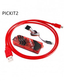
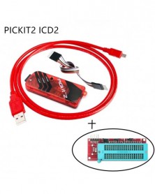
Szín: PIC KIT2 - PICKit2 PICKIT3 PICKit3.5 programozó PIC ICD2 PICKit 2 PICKIT 3 PICKIT 3.5 programozó adapter univerzális
1 286 Ft 2 679 FtProduct Description
PICkit3 is a development tool designed by Microchip for beginners to learn, evaluate and develop PIC series MCUs, integrating online simulation and downloading.
PIC series single-chip microcomputer is connected with PICkit3 through ICSP interface
Supported software:
Directly support Microchip's official IDE (integrated development environment software) MPLAB
Supported devices:
Support all PIC series microcontrollers with ICSP interface
Open the software, configure->select device PICKIT3 with a green light in front of it to indicate support.
8-bit Devices-PIC10F/12F/16F
PIC10F/12F/16F5X
PIC16F6xx
PIC16F7XX
PIC16F8XX
PIC16F9XX
PIC16F1XXX
8-bit Devices-PIC18F
PIC18CXX/FXX
PIC18F1XXX
PIC18F2XXX/4XXX/6XXX/8XXX
PIC18FXXJ
PIC18FXXK
16-bit Devices
dsPIC30F/33F, PIC24F/H
32-bit Devices
PIC32MX
Features
Programming function: Can burn and write FLASH ROM, EEPROM, etc.
Simulation function: supports various debugging methods such as full-speed running, single-step debugging, and breakpoint debugging.
Simulation performance: using USB interface for simulation debugging, single step debugging, breakpoint debugging, fast response speed!
Programming performance: using USB interface for ICSP download, fast download speed!
Use USB interface to connect to PC
PICkit3 development tool has built-in driver to realize high-speed USB communication.
Connection interface with target board
ICSP standard interface specified by PICkit3.
Firmware can be upgraded
In the future, Microchip will introduce more PIC models, and will also add new device models to the ICSP device support list. When you need to use the latest models in future development, upgrade kit3, and upgrade firmware programs, you will be able to support the new Model!
The upgrade method is automatic upgrade, and Microchip will provide an upgrade program.
Tool description:
The PICkit 3 programmer/debugger is a simple low-cost online debugger controlled by a PC running MPLAB IDE (v8.20 or higher) software on a Windows® platform.
PICkit3 can program and debug almost all series of PIC FLASH microcontroller chips such as Microchip's PIC10/12/16/18/24/32, dsPIC30/dsPIC33, etc. And PICkit3 can program Microchip's KEELOQ HCS series chips, MCP250xx CAN series chips, and EEPROM memory chips.
Compared with PICkit2, PICkit3 has the advantages of stable simulation, more supported models, and faster speed. It can stably support PIC16 PIC18 PIC24 DSPIC series MCU simulation and download.
Since the ICSP interface of PIC has only one row of 6PIN connectors, when connecting PICkit3 to the PIC target board, you need to pay attention to the left and right direction of the connection. Do not insert it backwards to avoid burning the PICkit3 downloader.
Status of PICkit3's LED indicator
The indicators have the following meanings:
Power:
Green, it lights up when it is powered on or connected to the target board.
Active:
Blue, it lights when the PICkit 3 has established communication with the PC or sending/receiving commands.
Status:
Green, lights up when the debugger is working normally (standby).
Yellow, lights up when the operation is busy.
Red, lights up when the debugger fails. -
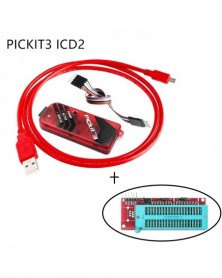
Szín: PIC KIT3 - PICKit2 PICKIT3 PICKit3.5 programozó PIC ICD2 PICKit 2 PICKIT 3 PICKIT 3.5 programozó adapter univerzális
1 791 Ft 3 732 FtProduct Description
PICkit3 is a development tool designed by Microchip for beginners to learn, evaluate and develop PIC series MCUs, integrating online simulation and downloading.
PIC series single-chip microcomputer is connected with PICkit3 through ICSP interface
Supported software:
Directly support Microchip's official IDE (integrated development environment software) MPLAB
Supported devices:
Support all PIC series microcontrollers with ICSP interface
Open the software, configure->select device PICKIT3 with a green light in front of it to indicate support.
8-bit Devices-PIC10F/12F/16F
PIC10F/12F/16F5X
PIC16F6xx
PIC16F7XX
PIC16F8XX
PIC16F9XX
PIC16F1XXX
8-bit Devices-PIC18F
PIC18CXX/FXX
PIC18F1XXX
PIC18F2XXX/4XXX/6XXX/8XXX
PIC18FXXJ
PIC18FXXK
16-bit Devices
dsPIC30F/33F, PIC24F/H
32-bit Devices
PIC32MX
Features
Programming function: Can burn and write FLASH ROM, EEPROM, etc.
Simulation function: supports various debugging methods such as full-speed running, single-step debugging, and breakpoint debugging.
Simulation performance: using USB interface for simulation debugging, single step debugging, breakpoint debugging, fast response speed!
Programming performance: using USB interface for ICSP download, fast download speed!
Use USB interface to connect to PC
PICkit3 development tool has built-in driver to realize high-speed USB communication.
Connection interface with target board
ICSP standard interface specified by PICkit3.
Firmware can be upgraded
In the future, Microchip will introduce more PIC models, and will also add new device models to the ICSP device support list. When you need to use the latest models in future development, upgrade kit3, and upgrade firmware programs, you will be able to support the new Model!
The upgrade method is automatic upgrade, and Microchip will provide an upgrade program.
Tool description:
The PICkit 3 programmer/debugger is a simple low-cost online debugger controlled by a PC running MPLAB IDE (v8.20 or higher) software on a Windows® platform.
PICkit3 can program and debug almost all series of PIC FLASH microcontroller chips such as Microchip's PIC10/12/16/18/24/32, dsPIC30/dsPIC33, etc. And PICkit3 can program Microchip's KEELOQ HCS series chips, MCP250xx CAN series chips, and EEPROM memory chips.
Compared with PICkit2, PICkit3 has the advantages of stable simulation, more supported models, and faster speed. It can stably support PIC16 PIC18 PIC24 DSPIC series MCU simulation and download.
Since the ICSP interface of PIC has only one row of 6PIN connectors, when connecting PICkit3 to the PIC target board, you need to pay attention to the left and right direction of the connection. Do not insert it backwards to avoid burning the PICkit3 downloader.
Status of PICkit3's LED indicator
The indicators have the following meanings:
Power:
Green, it lights up when it is powered on or connected to the target board.
Active:
Blue, it lights when the PICkit 3 has established communication with the PC or sending/receiving commands.
Status:
Green, lights up when the debugger is working normally (standby).
Yellow, lights up when the operation is busy.
Red, lights up when the debugger fails. -
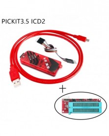
Szín: PIC KIT3.5 - PICKit2 PICKIT3 PICKit3.5 programozó PIC ICD2 PICKit 2 PICKIT 3 PICKIT 3.5 programozó adapter
2 014 Ft 4 196 FtProduct Description
PICkit3 is a development tool designed by Microchip for beginners to learn, evaluate and develop PIC series MCUs, integrating online simulation and downloading.
PIC series single-chip microcomputer is connected with PICkit3 through ICSP interface
Supported software:
Directly support Microchip's official IDE (integrated development environment software) MPLAB
Supported devices:
Support all PIC series microcontrollers with ICSP interface
Open the software, configure->select device PICKIT3 with a green light in front of it to indicate support.
8-bit Devices-PIC10F/12F/16F
PIC10F/12F/16F5X
PIC16F6xx
PIC16F7XX
PIC16F8XX
PIC16F9XX
PIC16F1XXX
8-bit Devices-PIC18F
PIC18CXX/FXX
PIC18F1XXX
PIC18F2XXX/4XXX/6XXX/8XXX
PIC18FXXJ
PIC18FXXK
16-bit Devices
dsPIC30F/33F, PIC24F/H
32-bit Devices
PIC32MX
Features
Programming function: Can burn and write FLASH ROM, EEPROM, etc.
Simulation function: supports various debugging methods such as full-speed running, single-step debugging, and breakpoint debugging.
Simulation performance: using USB interface for simulation debugging, single step debugging, breakpoint debugging, fast response speed!
Programming performance: using USB interface for ICSP download, fast download speed!
Use USB interface to connect to PC
PICkit3 development tool has built-in driver to realize high-speed USB communication.
Connection interface with target board
ICSP standard interface specified by PICkit3.
Firmware can be upgraded
In the future, Microchip will introduce more PIC models, and will also add new device models to the ICSP device support list. When you need to use the latest models in future development, upgrade kit3, and upgrade firmware programs, you will be able to support the new Model!
The upgrade method is automatic upgrade, and Microchip will provide an upgrade program.
Tool description:
The PICkit 3 programmer/debugger is a simple low-cost online debugger controlled by a PC running MPLAB IDE (v8.20 or higher) software on a Windows® platform.
PICkit3 can program and debug almost all series of PIC FLASH microcontroller chips such as Microchip's PIC10/12/16/18/24/32, dsPIC30/dsPIC33, etc. And PICkit3 can program Microchip's KEELOQ HCS series chips, MCP250xx CAN series chips, and EEPROM memory chips.
Compared with PICkit2, PICkit3 has the advantages of stable simulation, more supported models, and faster speed. It can stably support PIC16 PIC18 PIC24 DSPIC series MCU simulation and download.
Since the ICSP interface of PIC has only one row of 6PIN connectors, when connecting PICkit3 to the PIC target board, you need to pay attention to the left and right direction of the connection. Do not insert it backwards to avoid burning the PICkit3 downloader.
Status of PICkit3's LED indicator
The indicators have the following meanings:
Power:
Green, it lights up when it is powered on or connected to the target board.
Active:
Blue, it lights when the PICkit 3 has established communication with the PC or sending/receiving commands.
Status:
Green, lights up when the debugger is working normally (standby).
Yellow, lights up when the operation is busy.
Red, lights up when the debugger fails. -
Szín: PIC KIT2 ICD2 - PICKit2 PICKIT3 PICKit3.5 programozó PIC ICD2 PICKit 2 PICKIT 3 PICKIT 3.5 programozó adapter
1 372 Ft 2 858 FtProduct Description
PICkit3 is a development tool designed by Microchip for beginners to learn, evaluate and develop PIC series MCUs, integrating online simulation and downloading.
PIC series single-chip microcomputer is connected with PICkit3 through ICSP interface
Supported software:
Directly support Microchip's official IDE (integrated development environment software) MPLAB
Supported devices:
Support all PIC series microcontrollers with ICSP interface
Open the software, configure->select device PICKIT3 with a green light in front of it to indicate support.
8-bit Devices-PIC10F/12F/16F
PIC10F/12F/16F5X
PIC16F6xx
PIC16F7XX
PIC16F8XX
PIC16F9XX
PIC16F1XXX
8-bit Devices-PIC18F
PIC18CXX/FXX
PIC18F1XXX
PIC18F2XXX/4XXX/6XXX/8XXX
PIC18FXXJ
PIC18FXXK
16-bit Devices
dsPIC30F/33F, PIC24F/H
32-bit Devices
PIC32MX
Features
Programming function: Can burn and write FLASH ROM, EEPROM, etc.
Simulation function: supports various debugging methods such as full-speed running, single-step debugging, and breakpoint debugging.
Simulation performance: using USB interface for simulation debugging, single step debugging, breakpoint debugging, fast response speed!
Programming performance: using USB interface for ICSP download, fast download speed!
Use USB interface to connect to PC
PICkit3 development tool has built-in driver to realize high-speed USB communication.
Connection interface with target board
ICSP standard interface specified by PICkit3.
Firmware can be upgraded
In the future, Microchip will introduce more PIC models, and will also add new device models to the ICSP device support list. When you need to use the latest models in future development, upgrade kit3, and upgrade firmware programs, you will be able to support the new Model!
The upgrade method is automatic upgrade, and Microchip will provide an upgrade program.
Tool description:
The PICkit 3 programmer/debugger is a simple low-cost online debugger controlled by a PC running MPLAB IDE (v8.20 or higher) software on a Windows® platform.
PICkit3 can program and debug almost all series of PIC FLASH microcontroller chips such as Microchip's PIC10/12/16/18/24/32, dsPIC30/dsPIC33, etc. And PICkit3 can program Microchip's KEELOQ HCS series chips, MCP250xx CAN series chips, and EEPROM memory chips.
Compared with PICkit2, PICkit3 has the advantages of stable simulation, more supported models, and faster speed. It can stably support PIC16 PIC18 PIC24 DSPIC series MCU simulation and download.
Since the ICSP interface of PIC has only one row of 6PIN connectors, when connecting PICkit3 to the PIC target board, you need to pay attention to the left and right direction of the connection. Do not insert it backwards to avoid burning the PICkit3 downloader.
Status of PICkit3's LED indicator
The indicators have the following meanings:
Power:
Green, it lights up when it is powered on or connected to the target board.
Active:
Blue, it lights when the PICkit 3 has established communication with the PC or sending/receiving commands.
Status:
Green, lights up when the debugger is working normally (standby).
Yellow, lights up when the operation is busy.
Red, lights up when the debugger fails. -
Szín: PIC KIT3 ICD2 - PICKit2 PICKIT3 PICKit3.5 programozó PIC ICD2 PICKit 2 PICKIT 3 PICKIT 3.5 programozó adapter
1 877 Ft 3 911 FtProduct Description
PICkit3 is a development tool designed by Microchip for beginners to learn, evaluate and develop PIC series MCUs, integrating online simulation and downloading.
PIC series single-chip microcomputer is connected with PICkit3 through ICSP interface
Supported software:
Directly support Microchip's official IDE (integrated development environment software) MPLAB
Supported devices:
Support all PIC series microcontrollers with ICSP interface
Open the software, configure->select device PICKIT3 with a green light in front of it to indicate support.
8-bit Devices-PIC10F/12F/16F
PIC10F/12F/16F5X
PIC16F6xx
PIC16F7XX
PIC16F8XX
PIC16F9XX
PIC16F1XXX
8-bit Devices-PIC18F
PIC18CXX/FXX
PIC18F1XXX
PIC18F2XXX/4XXX/6XXX/8XXX
PIC18FXXJ
PIC18FXXK
16-bit Devices
dsPIC30F/33F, PIC24F/H
32-bit Devices
PIC32MX
Features
Programming function: Can burn and write FLASH ROM, EEPROM, etc.
Simulation function: supports various debugging methods such as full-speed running, single-step debugging, and breakpoint debugging.
Simulation performance: using USB interface for simulation debugging, single step debugging, breakpoint debugging, fast response speed!
Programming performance: using USB interface for ICSP download, fast download speed!
Use USB interface to connect to PC
PICkit3 development tool has built-in driver to realize high-speed USB communication.
Connection interface with target board
ICSP standard interface specified by PICkit3.
Firmware can be upgraded
In the future, Microchip will introduce more PIC models, and will also add new device models to the ICSP device support list. When you need to use the latest models in future development, upgrade kit3, and upgrade firmware programs, you will be able to support the new Model!
The upgrade method is automatic upgrade, and Microchip will provide an upgrade program.
Tool description:
The PICkit 3 programmer/debugger is a simple low-cost online debugger controlled by a PC running MPLAB IDE (v8.20 or higher) software on a Windows® platform.
PICkit3 can program and debug almost all series of PIC FLASH microcontroller chips such as Microchip's PIC10/12/16/18/24/32, dsPIC30/dsPIC33, etc. And PICkit3 can program Microchip's KEELOQ HCS series chips, MCP250xx CAN series chips, and EEPROM memory chips.
Compared with PICkit2, PICkit3 has the advantages of stable simulation, more supported models, and faster speed. It can stably support PIC16 PIC18 PIC24 DSPIC series MCU simulation and download.
Since the ICSP interface of PIC has only one row of 6PIN connectors, when connecting PICkit3 to the PIC target board, you need to pay attention to the left and right direction of the connection. Do not insert it backwards to avoid burning the PICkit3 downloader.
Status of PICkit3's LED indicator
The indicators have the following meanings:
Power:
Green, it lights up when it is powered on or connected to the target board.
Active:
Blue, it lights when the PICkit 3 has established communication with the PC or sending/receiving commands.
Status:
Green, lights up when the debugger is working normally (standby).
Yellow, lights up when the operation is busy.
Red, lights up when the debugger fails. -
Szín: PIC KIT3.5 ICD2 - PICKit2 PICKIT3 PICKit3.5 programozó PIC ICD2 PICKit 2 PICKIT 3 PICKIT 3.5 programozó adapter
2 100 Ft 4 375 FtProduct Description
PICkit3 is a development tool designed by Microchip for beginners to learn, evaluate and develop PIC series MCUs, integrating online simulation and downloading.
PIC series single-chip microcomputer is connected with PICkit3 through ICSP interface
Supported software:
Directly support Microchip's official IDE (integrated development environment software) MPLAB
Supported devices:
Support all PIC series microcontrollers with ICSP interface
Open the software, configure->select device PICKIT3 with a green light in front of it to indicate support.
8-bit Devices-PIC10F/12F/16F
PIC10F/12F/16F5X
PIC16F6xx
PIC16F7XX
PIC16F8XX
PIC16F9XX
PIC16F1XXX
8-bit Devices-PIC18F
PIC18CXX/FXX
PIC18F1XXX
PIC18F2XXX/4XXX/6XXX/8XXX
PIC18FXXJ
PIC18FXXK
16-bit Devices
dsPIC30F/33F, PIC24F/H
32-bit Devices
PIC32MX
Features
Programming function: Can burn and write FLASH ROM, EEPROM, etc.
Simulation function: supports various debugging methods such as full-speed running, single-step debugging, and breakpoint debugging.
Simulation performance: using USB interface for simulation debugging, single step debugging, breakpoint debugging, fast response speed!
Programming performance: using USB interface for ICSP download, fast download speed!
Use USB interface to connect to PC
PICkit3 development tool has built-in driver to realize high-speed USB communication.
Connection interface with target board
ICSP standard interface specified by PICkit3.
Firmware can be upgraded
In the future, Microchip will introduce more PIC models, and will also add new device models to the ICSP device support list. When you need to use the latest models in future development, upgrade kit3, and upgrade firmware programs, you will be able to support the new Model!
The upgrade method is automatic upgrade, and Microchip will provide an upgrade program.
Tool description:
The PICkit 3 programmer/debugger is a simple low-cost online debugger controlled by a PC running MPLAB IDE (v8.20 or higher) software on a Windows® platform.
PICkit3 can program and debug almost all series of PIC FLASH microcontroller chips such as Microchip's PIC10/12/16/18/24/32, dsPIC30/dsPIC33, etc. And PICkit3 can program Microchip's KEELOQ HCS series chips, MCP250xx CAN series chips, and EEPROM memory chips.
Compared with PICkit2, PICkit3 has the advantages of stable simulation, more supported models, and faster speed. It can stably support PIC16 PIC18 PIC24 DSPIC series MCU simulation and download.
Since the ICSP interface of PIC has only one row of 6PIN connectors, when connecting PICkit3 to the PIC target board, you need to pay attention to the left and right direction of the connection. Do not insert it backwards to avoid burning the PICkit3 downloader.
Status of PICkit3's LED indicator
The indicators have the following meanings:
Power:
Green, it lights up when it is powered on or connected to the target board.
Active:
Blue, it lights when the PICkit 3 has established communication with the PC or sending/receiving commands.
Status:
Green, lights up when the debugger is working normally (standby).
Yellow, lights up when the operation is busy.
Red, lights up when the debugger fails. -
12V24V digitális feszültség- és áramszabályozó modul, XL4016 nagy teljesítményű 8A DC szabályozókártya
657 Ft 1 369 FtIntroduction:
The module adopts XL4016 switch-type voltage regulator chip, cooperates with MBR10200 double rectification, and adds load protection circuit in the circuit to protect the load. The maximum instantaneous output current can reach 8A, and a fan is required to dissipate heat. It is recommended to be within 5A for long-term operation.
Main control chip used:
XL4016 is a switching step-down line DC-DC converter chip with a fixed switching frequency of 180KHz. The chip has excellent linear regulation and load regulation. The output voltage can be adjusted between 1.25V and 36V. The chip integrates reliability modules such as over-voltage protection, over-current protection, over-temperature protection, and short-circuit protection.
MBR Schottky diode is characterized by low forward voltage drop and high forward current. It can not only replace ordinary rectifier diodes for rectification circuits, but also replace fast recovery diodes for switching power supplies. In some cases, rectification is required. It is also suitable for occasions where the link loss voltage is low and the rectification is large.
LM358 operational amplifier
LM358 is a dual operational amplifier. There are two independent, high-gain, internal frequency-compensated operational amplifiers, which are suitable for single power supply with a wide range of power supply voltage, and also suitable for dual power supply mode. Under the recommended working conditions, the power supply current has nothing to do with the power supply voltage.
l Internal frequency compensation
l High DC voltage gain
l High potential gain (about 100dB)
l Low power consumption current, suitable for battery power supply
l Low input bias current, low input offset voltage and offset current
CD4051 electronic switch
CD4051 is a single-channel digital control analog electronic switch, with three binary input terminals A, B, C and INH input, with low on-resistance and very low cut-off leakage current. The digital signal with amplitude of 4.5~20V can control the peak value to 20V analog signal. For example, if VDD= 5V, VSS=0, VEE=-13.5V, the digital signal of 0~5V can control the analog signal of -13.5~4.5V. These switching circuits have extremely low static power consumption in the entire VDD-VSS and VDD-VEE power supply range, regardless of the logic state of the control signal. When INH input terminal = "1", all channels are cut off. Three-bit binary signal selection channel One of the 8 channels can be connected to the input terminal to the output.
XL1509 overview:
XL1509 is a 150KHz fixed frequency pulse width modulation (buck type) DC/DC converter. It has 2A load drive capability and high efficiency, low ripple and excellent linearity, good load regulation ability, and only requires a minimum of external components. Adjustable output is easy to use, built-in frequency compensation and fixed frequency oscillator.
The pulse width modulation control circuit can linearly adjust the duty cycle from 0 to 100% . With enabling function, built-in over-current and short-circuit protection functions, when over-current and short-circuit protection occurs, the operating frequency of the XL1509 is reduced from 150KHz to 50KHz. The built-in frequency compensation module minimizes damage to the external components of the XL1509. -
Nagy teljesítményű MOS cső térhatású kapcsoló trigger kapcsoló illesztőprogram modul PWM állítható elektronikus
102 Ft 213 FtProduct Description
High-power MOS tube Field effect tube Trigger switch drive module PWM adjustment electronic switch control board
Module highlights:
1. It adopts the original imported dual MOS parallel active output, lower internal resistance, higher current, strong power, 15A, 400W at room temperature, which can meet the use of most equipment;
2. Wide voltage, perfect support for PWM;
3. Easily realize the control of high-power equipment.
Product parameters and applications:
1: Working voltage: DC 5V--36V;
2: Trigger signal source: digital high and low level (DC3.3V--20V), can be connected to MCU IO port, PLC interface, DC power supply, etc., can be connected to PWM signal, signal frequency 0-20KHZ is perfectly supported.
3: Output capacity: DC 5V--36V, continuous current 15A at room temperature, power 400W! Under auxiliary heat dissipation conditions, the maximum current can reach 30A.
4: Application: The output terminal can control high-power equipment, motors, bulbs, LED strips, DC motors, micro water pumps, solenoid valves, etc., and can input PWM to control the motor speed, lamp brightness and so on.
5: Service life: unlimited switching; working temperature: -40—85°C; size: 3.4*1.7*1.2cm -
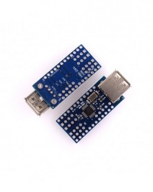
Mini USB Host Shield 2.0 az Arduino ADK tükörreflexes fejlesztőeszközhöz
1 540 Ft 3 209 FtDescription:
1. Support the Google for Android ADK, supporting for Android phone: G1, Nexus One, Nexus S, Droid X
(Mobile systems need to upgrade to for Android 2.3.4, tablet PCs need to upgrade to Android 3.1)
2. Provides APK package, and compiled source files ADK
3. Compatible with for arduino following hardware:
for arduino Uno 328
for arduino Diecimila / Duemilanove 328
for arduino Mega 2560 (recommended)
for arduino Mega 1280
4. After achieve the for arduino USB HOST function, you can communicate with other USB devices,
and support USB HUB function
5. Size: 38mm*18mm
6. Power Supply: DC3.3V
7. Interface: SPI