Kereskedelmi, irodai és ipari
-
3,7V 5V 6V 9V 12V-tól 15V/-15V DC DC átalakító Növelje Boost kettős feszültségű tápegység
275 Ft 549 Ft
Product Name: 3.7V 5V 6V 9V 12V to 15V/-15V DC DC Converter Step up Boost Dual Voltage Power supply
Packing list:
1 PCS 3.3V-13V TO ±15V Dual voltage DC DC Boost Converter Module
Description:
Input voltage DC 3.3 ~ 13V,output DC ±15V(Deviation is ±4% )
Maximum input current 1.8A
Maximum output current : Vo is 600A,-Vo is 120mA
Quiescent current: 3-4mA
DC DC Boost Converter Module working frequency 400kHz.
Operating temperature range : -40~ 125 Degrees Celsius
Storage temperature range : -65~ 150 Degrees Celsius
2.54mm pin pitch,for MCU Development Board Breadboard friendly.
Size : 25 x 16.3 x 6.6mm
Weight :3g
Internal Optimize Power MOSFET
High efficiency up to 90%
Built in Frequency Compensation
Built in Soft-Start Function
Built in Thermal Shutdown Function
Built in Current Limit Function
Note:
1 Due to the diode partial pressure, the voltage of -Vo is lower than Vo
2 In order to obtain a more stable voltage, it is recommended that the output is greater than 1MA
3 -Vo cannot be used alone, or no voltage output.But you can just use Vo
Applications
ADC/DAC/Operational Amplifier
RS232 RS485 RS422 Bus
Audio equipment
LCD power supply
Instrumentation equipment
ARM MCU FPGA/CPLD Board
Analog acquisition
Power amplifier/Speakers
multimeter
Attention :
This is a DC-DC voltage converter module,Must be noted when using:
1 Input voltage can not be greater than the maximum input range
2 Output power can not be greater than the maximum load for a long time
3 Input power must be greater than the output power, because the power consumption of the module itself
Q & A:
Q : Why output voltage is less than the nominal voltage
A : Input power supply power is too low.Test the input voltage with a multimeter,a t this time of the input voltage is very low
-
DC 3,5-12V 2A Touch Switch LED illesztőprogram vezérlő 5050 3528 SMD LED-hez
215 Ft 429 FtEasy to use :
Touch the "touch area", touch once "Turn on",Touch again "Turn off"
When "Turn on", Continuous touch reduce the brightness,Once again Continuous touch Increased brightness,And so on
Product Name: DC 3.5-12V 2A Touch Switch LED Driver Controller for 5050 3528 SMD LED
Packing list:
1 PCS DC 3.5-12V 2A Touch Switch LED Driver Controller
Description:
Working voltage : DC 3.5-13V(Perfect for 3.7V 5V 6V 9V 12V LED Driver)
Output Current: 30-2000MA
Maximum output power: 26W
Continuously adjustable brightness
Turn off consumption is only 10uA
Pin Size 31mm x 15mm x 3mm
Weight : about 1.3g
-
DC 6-24V 20W állítható fényerejű LED meghajtó PWM vezérlő DC-DC fokozatmentes állandó áram átalakító
183 Ft 365 FtProduct Name : DC 6-24V 20W Adjustable Brightness LED Driver PWM Controller DC-DC Step-down Constant Current Converter
Packing list:
1 PCS 20-900MA 6-25V Multifunction Handle adjustment LED driver Module
Description:
6-25V 900mA Step-down High Brightness LED Driver with 5000:1 Dimming
Working voltage : DC 6-25V(Perfect for 6V 9V 12V 18V 24V LED Driver)
Output Current: 20-900MA;By changing the RCS resistance, the maximum current can reach 1200MA
Maximum output power: 20W
Current regulation: 1 through through the handle, 2 through PWM control
Single pin on/off and brightness control using DC voltage or PWM
Up to 1MHz switching frequency
Typical 5% output current accuracy
Inherent open-circuit LED protection
High efficiency (up to 97% )
High-Side Current Sense
Hysteretic Control: No Compensation
Adjustable Constant LED Current
Size : 28 x 20 x 16MM(Handle not included)
Handle Size : Length 13MM,Diameter 6MM
Weight : 5g
Application 1: Wiring in accordance with the following figure, Adjust the current through the handle.
Application 2: Ignore the adjustable resistance, control the output current through the PWM port, the current is 0-900MA adjustable
Application 3 : Add an enable control switch based on application 1.
-
Auto Buck-Boost DC 1,5 V 1,8 V 2,5 V 3,3 V 3,7 V 5 V–3 V Boost-Buck átalakító kártya tápegység modul DD0603SB_3V
201 Ft 402 FtBelow item is powered by Canton-Power Ltd .
Product Name: Auto Buck-Boost DC DC 1.5V 1.8V 2.5V 3.3V 3.7V 5V to 3V Boost-Buck Converter Board Power Supply Module DD0603SB_3V
Packing list:
1 PCS DD0603SB_3V 0.9-6V TO 3V( -5% ) DC DC Boost-Buck Converter Module
Description:
Input voltage DC 0.9 ~ 6V, output DC 3V( -5% )
The maximum input voltage can not exceed 6.5V
Auto Buck-Boost Converter Module working frequency 1MHZ.efficiency 60% -85% .
Operating temperature range : -25~ 85 Degrees Celsius
Storage temperature range : -45~ 125 Degrees Celsius
Size : 22mm x 15mm x 5.7mm(Very small)
Weight : 2.3g(Very light)
Applications
Battery powered equipment
MCU Breadboard Power Supply
electrical tools
Small power motors
Camera, Video camera
Toy car
power bank
LED Lighting
Wireless communication equipment
Audio equipment
Attention :
This is a DC-DC voltage converter module,Must be noted when using:
1 Input voltage can not be greater than the maximum input range
2 Output power can not be greater than the maximum load for a long time
3 Input power must be greater than the output power, because the power consumption of the module itself
Q & A:
Q : Why output voltage is less than the nominal voltage
A : Input power supply power is too low.Test the input voltage with a multimeter,a t this time of the input voltage is very low
-
2 az 1-ben mini Low Noise Boost-Buck DC DC átalakító 1,8V-5V-3,3V szabályozott tápegység modul
236 Ft 472 Ft
Product Name: 2 in 1 mini Low Noise Boost-Buck DC DC Converter 1.8V-5V to 3.3V Regulated Power Supply Module
Packing list:
5 PCS 2 in 1 DC-DC Boost-Buck Converter 1.8V-5V to 3.3V module
Description:
Low Noise, Regulated Charge Pump DC/DC Converter
2 in 1 DC-DC Step-Down & Step-Up Converter module
Fixed 3.3V -4% Output
Voltage Input Range: 1.8~5V
Long time maximum output current 100mA
Short time maximum output current 150mA
working frequency 1.2MHz.
Short-Circuit Protection
No load input current : 0.65mA
Size 11mm x 7.6mm x 4.5mm(small)
Weight : 0.3g(Very very light)
Applications:
Low Power Wifi Module:ESP8266
Low-power Bluetooth module : HC-05 HC-06
Low-power Wireless UART module : HC-11 HC-12
Low-power wireless module : CC1101 CC2500 Nrf24l01
Low-power LED Driver
Attention :
This is a DC-DC voltage converter module,Must be noted when using:
1 Input voltage can not be greater than the maximum input range
2 Output power can not be greater than the maximum load for a long time
3 Input power must be greater than the output power, because the power consumption of the module itself
-
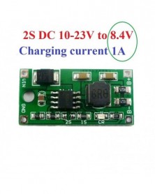
Szín: 1S2A - DC 5-23V - 4,2V 8,4V 12,6V 1S 2S 3S többcellás Li-Ion lítium akkumulátortöltő szoláris töltéshez
313 Ft 625 FtProduct Name: DC 5-23V to 4.2V 8.4V 12.6V 1S 2S 3S Multi-Cell Li-Ion Lithium Battery Charger for Solar charging Portable device
Packing list:
1 PCS 0.5A/1A/2A1/2/3-S synchronous Buck Li-Ion battery charger
(Please choose the parameters you need when purchasing)
Description:
1-Cell(1S) 4.2V Version:
Input voltage : DC 4.5V-23V(Recommend DC 5V/6V/9V/12V/15V)
Charging voltage : 4.2V
Charging current : 1A/2A(Please choose the parameters you need when purchasing)
2-Cell(2S) 8.4V Version:
Input voltage : DC 10-23V(Recommend DC 12V/14.8V/15V/18V)
Charging voltage : 8.4V
Charging current : 0.5A/1A(Please choose the parameters you need when purchasing)
3-Cell(3S) 12.6V Version:
Input voltage : DC 14.8-23V(Recommend DC 14.8V/15V/18V)
Charging voltage : 12.6V
Charging current : 0.5A/1A(Please choose the parameters you need when purchasing)
Led indicator :
Bright: Charging Off: full Blinking: almost full; If the charging current is too large (or the battery capacity is small), it will quickly enter the flashing state, and the charging current should be reduced.
Operating ambient temperature : -40° to 85°
Storage temperature : -65° to 125°
Size : 30*15*5.5mm
Weight : 2g
Applications:
Cellular Telephones,
PDA, MP3 Players, MP4 Players
Digital Cameras
Bluetooth Applications
Solar charging
Game Players
Notebook
li-on Lithium Battery 18650
Mobile phone
Solar charging
MP3/MP4 player
Audio equipment
Portable Devices
-
Szín: 1S1A - DC 5-23V - 4,2V 8,4V 12,6V 1S 2S 3S többcellás Li-Ion lítium akkumulátortöltő szoláris töltéshez
313 Ft 625 FtProduct Name: DC 5-23V to 4.2V 8.4V 12.6V 1S 2S 3S Multi-Cell Li-Ion Lithium Battery Charger for Solar charging Portable device
Packing list:
1 PCS 0.5A/1A/2A1/2/3-S synchronous Buck Li-Ion battery charger
(Please choose the parameters you need when purchasing)
Description:
1-Cell(1S) 4.2V Version:
Input voltage : DC 4.5V-23V(Recommend DC 5V/6V/9V/12V/15V)
Charging voltage : 4.2V
Charging current : 1A/2A(Please choose the parameters you need when purchasing)
2-Cell(2S) 8.4V Version:
Input voltage : DC 10-23V(Recommend DC 12V/14.8V/15V/18V)
Charging voltage : 8.4V
Charging current : 0.5A/1A(Please choose the parameters you need when purchasing)
3-Cell(3S) 12.6V Version:
Input voltage : DC 14.8-23V(Recommend DC 14.8V/15V/18V)
Charging voltage : 12.6V
Charging current : 0.5A/1A(Please choose the parameters you need when purchasing)
Led indicator :
Bright: Charging Off: full Blinking: almost full; If the charging current is too large (or the battery capacity is small), it will quickly enter the flashing state, and the charging current should be reduced.
Operating ambient temperature : -40° to 85°
Storage temperature : -65° to 125°
Size : 30*15*5.5mm
Weight : 2g
Applications:
Cellular Telephones,
PDA, MP3 Players, MP4 Players
Digital Cameras
Bluetooth Applications
Solar charging
Game Players
Notebook
li-on Lithium Battery 18650
Mobile phone
Solar charging
MP3/MP4 player
Audio equipment
Portable Devices
-
Szín: 2S1A - DC 5-23V - 4,2V 8,4V 12,6V 1S 2S 3S többcellás Li-Ion lítium akkumulátortöltő szoláris töltéshez
313 Ft 625 FtProduct Name: DC 5-23V to 4.2V 8.4V 12.6V 1S 2S 3S Multi-Cell Li-Ion Lithium Battery Charger for Solar charging Portable device
Packing list:
1 PCS 0.5A/1A/2A1/2/3-S synchronous Buck Li-Ion battery charger
(Please choose the parameters you need when purchasing)
Description:
1-Cell(1S) 4.2V Version:
Input voltage : DC 4.5V-23V(Recommend DC 5V/6V/9V/12V/15V)
Charging voltage : 4.2V
Charging current : 1A/2A(Please choose the parameters you need when purchasing)
2-Cell(2S) 8.4V Version:
Input voltage : DC 10-23V(Recommend DC 12V/14.8V/15V/18V)
Charging voltage : 8.4V
Charging current : 0.5A/1A(Please choose the parameters you need when purchasing)
3-Cell(3S) 12.6V Version:
Input voltage : DC 14.8-23V(Recommend DC 14.8V/15V/18V)
Charging voltage : 12.6V
Charging current : 0.5A/1A(Please choose the parameters you need when purchasing)
Led indicator :
Bright: Charging Off: full Blinking: almost full; If the charging current is too large (or the battery capacity is small), it will quickly enter the flashing state, and the charging current should be reduced.
Operating ambient temperature : -40° to 85°
Storage temperature : -65° to 125°
Size : 30*15*5.5mm
Weight : 2g
Applications:
Cellular Telephones,
PDA, MP3 Players, MP4 Players
Digital Cameras
Bluetooth Applications
Solar charging
Game Players
Notebook
li-on Lithium Battery 18650
Mobile phone
Solar charging
MP3/MP4 player
Audio equipment
Portable Devices
-
Szín: 2S05A - DC 5-23V - 4,2V 8,4V 12,6V 1S 2S 3S többcellás Li-Ion lítium akkumulátortöltő szoláris töltéshez
313 Ft 625 FtProduct Name: DC 5-23V to 4.2V 8.4V 12.6V 1S 2S 3S Multi-Cell Li-Ion Lithium Battery Charger for Solar charging Portable device
Packing list:
1 PCS 0.5A/1A/2A1/2/3-S synchronous Buck Li-Ion battery charger
(Please choose the parameters you need when purchasing)
Description:
1-Cell(1S) 4.2V Version:
Input voltage : DC 4.5V-23V(Recommend DC 5V/6V/9V/12V/15V)
Charging voltage : 4.2V
Charging current : 1A/2A(Please choose the parameters you need when purchasing)
2-Cell(2S) 8.4V Version:
Input voltage : DC 10-23V(Recommend DC 12V/14.8V/15V/18V)
Charging voltage : 8.4V
Charging current : 0.5A/1A(Please choose the parameters you need when purchasing)
3-Cell(3S) 12.6V Version:
Input voltage : DC 14.8-23V(Recommend DC 14.8V/15V/18V)
Charging voltage : 12.6V
Charging current : 0.5A/1A(Please choose the parameters you need when purchasing)
Led indicator :
Bright: Charging Off: full Blinking: almost full; If the charging current is too large (or the battery capacity is small), it will quickly enter the flashing state, and the charging current should be reduced.
Operating ambient temperature : -40° to 85°
Storage temperature : -65° to 125°
Size : 30*15*5.5mm
Weight : 2g
Applications:
Cellular Telephones,
PDA, MP3 Players, MP4 Players
Digital Cameras
Bluetooth Applications
Solar charging
Game Players
Notebook
li-on Lithium Battery 18650
Mobile phone
Solar charging
MP3/MP4 player
Audio equipment
Portable Devices
-
Szín: 3S1A - DC 5-23V - 4,2V 8,4V 12,6V 1S 2S 3S többcellás Li-Ion lítium akkumulátortöltő szoláris töltéshez
313 Ft 625 FtProduct Name: DC 5-23V to 4.2V 8.4V 12.6V 1S 2S 3S Multi-Cell Li-Ion Lithium Battery Charger for Solar charging Portable device
Packing list:
1 PCS 0.5A/1A/2A1/2/3-S synchronous Buck Li-Ion battery charger
(Please choose the parameters you need when purchasing)
Description:
1-Cell(1S) 4.2V Version:
Input voltage : DC 4.5V-23V(Recommend DC 5V/6V/9V/12V/15V)
Charging voltage : 4.2V
Charging current : 1A/2A(Please choose the parameters you need when purchasing)
2-Cell(2S) 8.4V Version:
Input voltage : DC 10-23V(Recommend DC 12V/14.8V/15V/18V)
Charging voltage : 8.4V
Charging current : 0.5A/1A(Please choose the parameters you need when purchasing)
3-Cell(3S) 12.6V Version:
Input voltage : DC 14.8-23V(Recommend DC 14.8V/15V/18V)
Charging voltage : 12.6V
Charging current : 0.5A/1A(Please choose the parameters you need when purchasing)
Led indicator :
Bright: Charging Off: full Blinking: almost full; If the charging current is too large (or the battery capacity is small), it will quickly enter the flashing state, and the charging current should be reduced.
Operating ambient temperature : -40° to 85°
Storage temperature : -65° to 125°
Size : 30*15*5.5mm
Weight : 2g
Applications:
Cellular Telephones,
PDA, MP3 Players, MP4 Players
Digital Cameras
Bluetooth Applications
Solar charging
Game Players
Notebook
li-on Lithium Battery 18650
Mobile phone
Solar charging
MP3/MP4 player
Audio equipment
Portable Devices
-
Szín: 3S05A - DC 5-23V - 4,2V 8,4V 12,6V 1S 2S 3S többcellás Li-Ion lítium akkumulátortöltő szoláris töltéshez
313 Ft 625 FtProduct Name: DC 5-23V to 4.2V 8.4V 12.6V 1S 2S 3S Multi-Cell Li-Ion Lithium Battery Charger for Solar charging Portable device
Packing list:
1 PCS 0.5A/1A/2A1/2/3-S synchronous Buck Li-Ion battery charger
(Please choose the parameters you need when purchasing)
Description:
1-Cell(1S) 4.2V Version:
Input voltage : DC 4.5V-23V(Recommend DC 5V/6V/9V/12V/15V)
Charging voltage : 4.2V
Charging current : 1A/2A(Please choose the parameters you need when purchasing)
2-Cell(2S) 8.4V Version:
Input voltage : DC 10-23V(Recommend DC 12V/14.8V/15V/18V)
Charging voltage : 8.4V
Charging current : 0.5A/1A(Please choose the parameters you need when purchasing)
3-Cell(3S) 12.6V Version:
Input voltage : DC 14.8-23V(Recommend DC 14.8V/15V/18V)
Charging voltage : 12.6V
Charging current : 0.5A/1A(Please choose the parameters you need when purchasing)
Led indicator :
Bright: Charging Off: full Blinking: almost full; If the charging current is too large (or the battery capacity is small), it will quickly enter the flashing state, and the charging current should be reduced.
Operating ambient temperature : -40° to 85°
Storage temperature : -65° to 125°
Size : 30*15*5.5mm
Weight : 2g
Applications:
Cellular Telephones,
PDA, MP3 Players, MP4 Players
Digital Cameras
Bluetooth Applications
Solar charging
Game Players
Notebook
li-on Lithium Battery 18650
Mobile phone
Solar charging
MP3/MP4 player
Audio equipment
Portable Devices
-
10db 1A mini Li Lithium akkumulátortöltő modul kártya Arduino UNO MEGA DUE Breadboard PCB 18650 napelemes mobil
503 Ft 1 006 Ft
Product Name: 10pcs 1A mini Li Lithium Battery Charger Module Board for Ardiuno UNO MEGA DUE Breadboard PCB 18650 solar panel mobile power
Packing list:
10 PCS DD08CRMB Ultra-small Li Lithium Battery Charger Module
Description:
Mini Lithium Battery Charger Module - Linear charging.
Input voltage : DC 4.5V-8V(Recommend DC 5V)
Maximum charging current : 1000MA
Full charge voltage : 4.2V -2% .
Led indicator : "OK" LED is fully charged OR battery failure status indicator;
"CR" LED is charge status indicator
Operating ambient temperature : -40° to 85°
Storage temperature : -65° to 125°
Size : 12.3mm*10mm*4mm( very small!!!)
Weight : 0.5g( Very light!!!)
Can be used DC 5-6V power supply charger(Such as Solar panels)Charging module comes with charge-management functions, will not overcharge or over discharge
Comes with rechargeable function,Will enter standby mode when fully charged.When the battery capacity is below 80% , the charging start.
Applications:
Battery powered equipment
Lithium Battery 18650 14500
Mobile phone
Solar charging
MP3/MP4 player
Audio equipment
Portable Devices
Bluetooth Applications
-
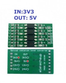
Szín: IN3V3 OUT3V3 - 4 csatornás 3,3 V 5 V 12 V 24 V digitális logikai szint átalakító modul PNP/NPN-ről NPN optikai
122 Ft 243 FtProduct Name: 4ch 3.3V 5V 12V 24V Digital Logic Level Conversion Module PNP/NPN to NPN Optical Isolation Board for Arduiuo UNO NANO STM32 AVR
Packing included:
1 PCS 4-chanels 3.3V 5V 12V 24V to photoelectric isolation logic level conversion module
Features
1. Multiple usage Used for signal isolation, PLC level conversion, PNP/NPN to PNP signal, signal level voltage conversion, etc.
2. Use original brand new Taiwanese coupler
3. Limit switching frequency up to 10KHZ
4 Arduiuo NANO UNO esp8266 raspberry pi
5. Size:38mm*20mm*5mm
6. Weight:3.9g
Module wiring terminal and definition:
Function Label Instruction
Signal Input 1 The first signal input anode
1- The first signal input cathode
2 The second signal input anode
2- The second signal input cathode
3 The third signal input anode
3- The third signal input cathode
4 The fourth signal input anode
4- The fourth signal input cathode
Power Input VCC DC power anode(*)
GND DC power supply cathode
Signal Output O1 The first signal output
O2 The second signal output
O3 The third signal output
O4 The fourth signal output
(*):The DC power supply is the same as the signal output voltage. For example, if the signal is from 3.3V to 5V, then VCC=5V input.
Schematic diagram of the internal structure of the module:
Module connection diagram:
Common anode signal(NPN) input
Input and output truth table
Signal Input Signal Output
H(High level)5V L(Low level)0V
L(Low level)0V H(High level)24V
Note:In this example, the anode of the signal power supply is DC 5v, and the anode of the module power supply is DC 24V
Common cathode signal input:
Common cathode signal(PNP) input:
Input and output truth table
Signal Input Signal Output
H(High level)5V H(High level)24V
L(Low level)0V L(Low level)0V
Note:In this example,Module power supply is DC 24V
Differential signal input:
Input and output truth table
Signal Input Signal Output
H(High level) H(High level)24V
L(Low level) L(Low level)0V
Note:In this example,Module power supply is DC 24V
-
Szín: IN3V3 OUT5V - 4 csatornás 3,3 V 5 V 12 V 24 V digitális logikai szint átalakító modul PNP/NPN-ről NPN optikai
122 Ft 243 FtProduct Name: 4ch 3.3V 5V 12V 24V Digital Logic Level Conversion Module PNP/NPN to NPN Optical Isolation Board for Arduiuo UNO NANO STM32 AVR
Packing included:
1 PCS 4-chanels 3.3V 5V 12V 24V to photoelectric isolation logic level conversion module
Features
1. Multiple usage Used for signal isolation, PLC level conversion, PNP/NPN to PNP signal, signal level voltage conversion, etc.
2. Use original brand new Taiwanese coupler
3. Limit switching frequency up to 10KHZ
4 Arduiuo NANO UNO esp8266 raspberry pi
5. Size:38mm*20mm*5mm
6. Weight:3.9g
Module wiring terminal and definition:
Function Label Instruction
Signal Input 1 The first signal input anode
1- The first signal input cathode
2 The second signal input anode
2- The second signal input cathode
3 The third signal input anode
3- The third signal input cathode
4 The fourth signal input anode
4- The fourth signal input cathode
Power Input VCC DC power anode(*)
GND DC power supply cathode
Signal Output O1 The first signal output
O2 The second signal output
O3 The third signal output
O4 The fourth signal output
(*):The DC power supply is the same as the signal output voltage. For example, if the signal is from 3.3V to 5V, then VCC=5V input.
Schematic diagram of the internal structure of the module:
Module connection diagram:
Common anode signal(NPN) input
Input and output truth table
Signal Input Signal Output
H(High level)5V L(Low level)0V
L(Low level)0V H(High level)24V
Note:In this example, the anode of the signal power supply is DC 5v, and the anode of the module power supply is DC 24V
Common cathode signal input:
Common cathode signal(PNP) input:
Input and output truth table
Signal Input Signal Output
H(High level)5V H(High level)24V
L(Low level)0V L(Low level)0V
Note:In this example,Module power supply is DC 24V
Differential signal input:
Input and output truth table
Signal Input Signal Output
H(High level) H(High level)24V
L(Low level) L(Low level)0V
Note:In this example,Module power supply is DC 24V
-
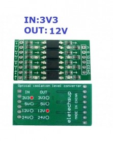
Szín: IN3V3 OUT12V - 4 csatornás 3,3 V 5 V 12 V 24 V digitális logikai szint átalakító modul PNP/NPN-ről NPN optikai
122 Ft 243 FtProduct Name: 4ch 3.3V 5V 12V 24V Digital Logic Level Conversion Module PNP/NPN to NPN Optical Isolation Board for Arduiuo UNO NANO STM32 AVR
Packing included:
1 PCS 4-chanels 3.3V 5V 12V 24V to photoelectric isolation logic level conversion module
Features
1. Multiple usage Used for signal isolation, PLC level conversion, PNP/NPN to PNP signal, signal level voltage conversion, etc.
2. Use original brand new Taiwanese coupler
3. Limit switching frequency up to 10KHZ
4 Arduiuo NANO UNO esp8266 raspberry pi
5. Size:38mm*20mm*5mm
6. Weight:3.9g
Module wiring terminal and definition:
Function Label Instruction
Signal Input 1 The first signal input anode
1- The first signal input cathode
2 The second signal input anode
2- The second signal input cathode
3 The third signal input anode
3- The third signal input cathode
4 The fourth signal input anode
4- The fourth signal input cathode
Power Input VCC DC power anode(*)
GND DC power supply cathode
Signal Output O1 The first signal output
O2 The second signal output
O3 The third signal output
O4 The fourth signal output
(*):The DC power supply is the same as the signal output voltage. For example, if the signal is from 3.3V to 5V, then VCC=5V input.
Schematic diagram of the internal structure of the module:
Module connection diagram:
Common anode signal(NPN) input
Input and output truth table
Signal Input Signal Output
H(High level)5V L(Low level)0V
L(Low level)0V H(High level)24V
Note:In this example, the anode of the signal power supply is DC 5v, and the anode of the module power supply is DC 24V
Common cathode signal input:
Common cathode signal(PNP) input:
Input and output truth table
Signal Input Signal Output
H(High level)5V H(High level)24V
L(Low level)0V L(Low level)0V
Note:In this example,Module power supply is DC 24V
Differential signal input:
Input and output truth table
Signal Input Signal Output
H(High level) H(High level)24V
L(Low level) L(Low level)0V
Note:In this example,Module power supply is DC 24V
-
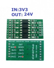
Szín: IN3V3 OUT24V - 4 csatornás 3,3 V 5 V 12 V 24 V digitális logikai szint átalakító modul PNP/NPN-ről NPN optikai
122 Ft 243 FtProduct Name: 4ch 3.3V 5V 12V 24V Digital Logic Level Conversion Module PNP/NPN to NPN Optical Isolation Board for Arduiuo UNO NANO STM32 AVR
Packing included:
1 PCS 4-chanels 3.3V 5V 12V 24V to photoelectric isolation logic level conversion module
Features
1. Multiple usage Used for signal isolation, PLC level conversion, PNP/NPN to PNP signal, signal level voltage conversion, etc.
2. Use original brand new Taiwanese coupler
3. Limit switching frequency up to 10KHZ
4 Arduiuo NANO UNO esp8266 raspberry pi
5. Size:38mm*20mm*5mm
6. Weight:3.9g
Module wiring terminal and definition:
Function Label Instruction
Signal Input 1 The first signal input anode
1- The first signal input cathode
2 The second signal input anode
2- The second signal input cathode
3 The third signal input anode
3- The third signal input cathode
4 The fourth signal input anode
4- The fourth signal input cathode
Power Input VCC DC power anode(*)
GND DC power supply cathode
Signal Output O1 The first signal output
O2 The second signal output
O3 The third signal output
O4 The fourth signal output
(*):The DC power supply is the same as the signal output voltage. For example, if the signal is from 3.3V to 5V, then VCC=5V input.
Schematic diagram of the internal structure of the module:
Module connection diagram:
Common anode signal(NPN) input
Input and output truth table
Signal Input Signal Output
H(High level)5V L(Low level)0V
L(Low level)0V H(High level)24V
Note:In this example, the anode of the signal power supply is DC 5v, and the anode of the module power supply is DC 24V
Common cathode signal input:
Common cathode signal(PNP) input:
Input and output truth table
Signal Input Signal Output
H(High level)5V H(High level)24V
L(Low level)0V L(Low level)0V
Note:In this example,Module power supply is DC 24V
Differential signal input:
Input and output truth table
Signal Input Signal Output
H(High level) H(High level)24V
L(Low level) L(Low level)0V
Note:In this example,Module power supply is DC 24V
-
Szín: IN5V OUT3V3 - 4 csatornás 3,3 V 5 V 12 V 24 V digitális logikai szint átalakító modul PNP/NPN-ről NPN optikai
122 Ft 243 FtProduct Name: 4ch 3.3V 5V 12V 24V Digital Logic Level Conversion Module PNP/NPN to NPN Optical Isolation Board for Arduiuo UNO NANO STM32 AVR
Packing included:
1 PCS 4-chanels 3.3V 5V 12V 24V to photoelectric isolation logic level conversion module
Features
1. Multiple usage Used for signal isolation, PLC level conversion, PNP/NPN to PNP signal, signal level voltage conversion, etc.
2. Use original brand new Taiwanese coupler
3. Limit switching frequency up to 10KHZ
4 Arduiuo NANO UNO esp8266 raspberry pi
5. Size:38mm*20mm*5mm
6. Weight:3.9g
Module wiring terminal and definition:
Function Label Instruction
Signal Input 1 The first signal input anode
1- The first signal input cathode
2 The second signal input anode
2- The second signal input cathode
3 The third signal input anode
3- The third signal input cathode
4 The fourth signal input anode
4- The fourth signal input cathode
Power Input VCC DC power anode(*)
GND DC power supply cathode
Signal Output O1 The first signal output
O2 The second signal output
O3 The third signal output
O4 The fourth signal output
(*):The DC power supply is the same as the signal output voltage. For example, if the signal is from 3.3V to 5V, then VCC=5V input.
Schematic diagram of the internal structure of the module:
Module connection diagram:
Common anode signal(NPN) input
Input and output truth table
Signal Input Signal Output
H(High level)5V L(Low level)0V
L(Low level)0V H(High level)24V
Note:In this example, the anode of the signal power supply is DC 5v, and the anode of the module power supply is DC 24V
Common cathode signal input:
Common cathode signal(PNP) input:
Input and output truth table
Signal Input Signal Output
H(High level)5V H(High level)24V
L(Low level)0V L(Low level)0V
Note:In this example,Module power supply is DC 24V
Differential signal input:
Input and output truth table
Signal Input Signal Output
H(High level) H(High level)24V
L(Low level) L(Low level)0V
Note:In this example,Module power supply is DC 24V
-
Szín: IN5V OUT5V - 4 csatornás 3,3 V 5 V 12 V 24 V digitális logikai szint átalakító modul PNP/NPN-ről NPN optikai
122 Ft 243 FtProduct Name: 4ch 3.3V 5V 12V 24V Digital Logic Level Conversion Module PNP/NPN to NPN Optical Isolation Board for Arduiuo UNO NANO STM32 AVR
Packing included:
1 PCS 4-chanels 3.3V 5V 12V 24V to photoelectric isolation logic level conversion module
Features
1. Multiple usage Used for signal isolation, PLC level conversion, PNP/NPN to PNP signal, signal level voltage conversion, etc.
2. Use original brand new Taiwanese coupler
3. Limit switching frequency up to 10KHZ
4 Arduiuo NANO UNO esp8266 raspberry pi
5. Size:38mm*20mm*5mm
6. Weight:3.9g
Module wiring terminal and definition:
Function Label Instruction
Signal Input 1 The first signal input anode
1- The first signal input cathode
2 The second signal input anode
2- The second signal input cathode
3 The third signal input anode
3- The third signal input cathode
4 The fourth signal input anode
4- The fourth signal input cathode
Power Input VCC DC power anode(*)
GND DC power supply cathode
Signal Output O1 The first signal output
O2 The second signal output
O3 The third signal output
O4 The fourth signal output
(*):The DC power supply is the same as the signal output voltage. For example, if the signal is from 3.3V to 5V, then VCC=5V input.
Schematic diagram of the internal structure of the module:
Module connection diagram:
Common anode signal(NPN) input
Input and output truth table
Signal Input Signal Output
H(High level)5V L(Low level)0V
L(Low level)0V H(High level)24V
Note:In this example, the anode of the signal power supply is DC 5v, and the anode of the module power supply is DC 24V
Common cathode signal input:
Common cathode signal(PNP) input:
Input and output truth table
Signal Input Signal Output
H(High level)5V H(High level)24V
L(Low level)0V L(Low level)0V
Note:In this example,Module power supply is DC 24V
Differential signal input:
Input and output truth table
Signal Input Signal Output
H(High level) H(High level)24V
L(Low level) L(Low level)0V
Note:In this example,Module power supply is DC 24V
-
Szín: IN5V OUT12V - 4 csatornás 3,3 V 5 V 12 V 24 V digitális logikai szint átalakító modul PNP/NPN-ről NPN optikai
122 Ft 243 FtProduct Name: 4ch 3.3V 5V 12V 24V Digital Logic Level Conversion Module PNP/NPN to NPN Optical Isolation Board for Arduiuo UNO NANO STM32 AVR
Packing included:
1 PCS 4-chanels 3.3V 5V 12V 24V to photoelectric isolation logic level conversion module
Features
1. Multiple usage Used for signal isolation, PLC level conversion, PNP/NPN to PNP signal, signal level voltage conversion, etc.
2. Use original brand new Taiwanese coupler
3. Limit switching frequency up to 10KHZ
4 Arduiuo NANO UNO esp8266 raspberry pi
5. Size:38mm*20mm*5mm
6. Weight:3.9g
Module wiring terminal and definition:
Function Label Instruction
Signal Input 1 The first signal input anode
1- The first signal input cathode
2 The second signal input anode
2- The second signal input cathode
3 The third signal input anode
3- The third signal input cathode
4 The fourth signal input anode
4- The fourth signal input cathode
Power Input VCC DC power anode(*)
GND DC power supply cathode
Signal Output O1 The first signal output
O2 The second signal output
O3 The third signal output
O4 The fourth signal output
(*):The DC power supply is the same as the signal output voltage. For example, if the signal is from 3.3V to 5V, then VCC=5V input.
Schematic diagram of the internal structure of the module:
Module connection diagram:
Common anode signal(NPN) input
Input and output truth table
Signal Input Signal Output
H(High level)5V L(Low level)0V
L(Low level)0V H(High level)24V
Note:In this example, the anode of the signal power supply is DC 5v, and the anode of the module power supply is DC 24V
Common cathode signal input:
Common cathode signal(PNP) input:
Input and output truth table
Signal Input Signal Output
H(High level)5V H(High level)24V
L(Low level)0V L(Low level)0V
Note:In this example,Module power supply is DC 24V
Differential signal input:
Input and output truth table
Signal Input Signal Output
H(High level) H(High level)24V
L(Low level) L(Low level)0V
Note:In this example,Module power supply is DC 24V
-
Szín: IN5V OUT24V - 4 csatornás 3,3 V 5 V 12 V 24 V digitális logikai szint átalakító modul PNP/NPN-ről NPN optikai
122 Ft 243 FtProduct Name: 4ch 3.3V 5V 12V 24V Digital Logic Level Conversion Module PNP/NPN to NPN Optical Isolation Board for Arduiuo UNO NANO STM32 AVR
Packing included:
1 PCS 4-chanels 3.3V 5V 12V 24V to photoelectric isolation logic level conversion module
Features
1. Multiple usage Used for signal isolation, PLC level conversion, PNP/NPN to PNP signal, signal level voltage conversion, etc.
2. Use original brand new Taiwanese coupler
3. Limit switching frequency up to 10KHZ
4 Arduiuo NANO UNO esp8266 raspberry pi
5. Size:38mm*20mm*5mm
6. Weight:3.9g
Module wiring terminal and definition:
Function Label Instruction
Signal Input 1 The first signal input anode
1- The first signal input cathode
2 The second signal input anode
2- The second signal input cathode
3 The third signal input anode
3- The third signal input cathode
4 The fourth signal input anode
4- The fourth signal input cathode
Power Input VCC DC power anode(*)
GND DC power supply cathode
Signal Output O1 The first signal output
O2 The second signal output
O3 The third signal output
O4 The fourth signal output
(*):The DC power supply is the same as the signal output voltage. For example, if the signal is from 3.3V to 5V, then VCC=5V input.
Schematic diagram of the internal structure of the module:
Module connection diagram:
Common anode signal(NPN) input
Input and output truth table
Signal Input Signal Output
H(High level)5V L(Low level)0V
L(Low level)0V H(High level)24V
Note:In this example, the anode of the signal power supply is DC 5v, and the anode of the module power supply is DC 24V
Common cathode signal input:
Common cathode signal(PNP) input:
Input and output truth table
Signal Input Signal Output
H(High level)5V H(High level)24V
L(Low level)0V L(Low level)0V
Note:In this example,Module power supply is DC 24V
Differential signal input:
Input and output truth table
Signal Input Signal Output
H(High level) H(High level)24V
L(Low level) L(Low level)0V
Note:In this example,Module power supply is DC 24V
-
Szín: IN12V OUT3V3 - 4 csatornás 3,3 V 5 V 12 V 24 V digitális logikai szint átalakító modul PNP/NPN-ről NPN optikai
122 Ft 243 FtProduct Name: 4ch 3.3V 5V 12V 24V Digital Logic Level Conversion Module PNP/NPN to NPN Optical Isolation Board for Arduiuo UNO NANO STM32 AVR
Packing included:
1 PCS 4-chanels 3.3V 5V 12V 24V to photoelectric isolation logic level conversion module
Features
1. Multiple usage Used for signal isolation, PLC level conversion, PNP/NPN to PNP signal, signal level voltage conversion, etc.
2. Use original brand new Taiwanese coupler
3. Limit switching frequency up to 10KHZ
4 Arduiuo NANO UNO esp8266 raspberry pi
5. Size:38mm*20mm*5mm
6. Weight:3.9g
Module wiring terminal and definition:
Function Label Instruction
Signal Input 1 The first signal input anode
1- The first signal input cathode
2 The second signal input anode
2- The second signal input cathode
3 The third signal input anode
3- The third signal input cathode
4 The fourth signal input anode
4- The fourth signal input cathode
Power Input VCC DC power anode(*)
GND DC power supply cathode
Signal Output O1 The first signal output
O2 The second signal output
O3 The third signal output
O4 The fourth signal output
(*):The DC power supply is the same as the signal output voltage. For example, if the signal is from 3.3V to 5V, then VCC=5V input.
Schematic diagram of the internal structure of the module:
Module connection diagram:
Common anode signal(NPN) input
Input and output truth table
Signal Input Signal Output
H(High level)5V L(Low level)0V
L(Low level)0V H(High level)24V
Note:In this example, the anode of the signal power supply is DC 5v, and the anode of the module power supply is DC 24V
Common cathode signal input:
Common cathode signal(PNP) input:
Input and output truth table
Signal Input Signal Output
H(High level)5V H(High level)24V
L(Low level)0V L(Low level)0V
Note:In this example,Module power supply is DC 24V
Differential signal input:
Input and output truth table
Signal Input Signal Output
H(High level) H(High level)24V
L(Low level) L(Low level)0V
Note:In this example,Module power supply is DC 24V
-
Szín: IN12V OUT5V - 4 csatornás 3,3 V 5 V 12 V 24 V digitális logikai szint átalakító modul PNP/NPN-ről NPN optikai
122 Ft 243 FtProduct Name: 4ch 3.3V 5V 12V 24V Digital Logic Level Conversion Module PNP/NPN to NPN Optical Isolation Board for Arduiuo UNO NANO STM32 AVR
Packing included:
1 PCS 4-chanels 3.3V 5V 12V 24V to photoelectric isolation logic level conversion module
Features
1. Multiple usage Used for signal isolation, PLC level conversion, PNP/NPN to PNP signal, signal level voltage conversion, etc.
2. Use original brand new Taiwanese coupler
3. Limit switching frequency up to 10KHZ
4 Arduiuo NANO UNO esp8266 raspberry pi
5. Size:38mm*20mm*5mm
6. Weight:3.9g
Module wiring terminal and definition:
Function Label Instruction
Signal Input 1 The first signal input anode
1- The first signal input cathode
2 The second signal input anode
2- The second signal input cathode
3 The third signal input anode
3- The third signal input cathode
4 The fourth signal input anode
4- The fourth signal input cathode
Power Input VCC DC power anode(*)
GND DC power supply cathode
Signal Output O1 The first signal output
O2 The second signal output
O3 The third signal output
O4 The fourth signal output
(*):The DC power supply is the same as the signal output voltage. For example, if the signal is from 3.3V to 5V, then VCC=5V input.
Schematic diagram of the internal structure of the module:
Module connection diagram:
Common anode signal(NPN) input
Input and output truth table
Signal Input Signal Output
H(High level)5V L(Low level)0V
L(Low level)0V H(High level)24V
Note:In this example, the anode of the signal power supply is DC 5v, and the anode of the module power supply is DC 24V
Common cathode signal input:
Common cathode signal(PNP) input:
Input and output truth table
Signal Input Signal Output
H(High level)5V H(High level)24V
L(Low level)0V L(Low level)0V
Note:In this example,Module power supply is DC 24V
Differential signal input:
Input and output truth table
Signal Input Signal Output
H(High level) H(High level)24V
L(Low level) L(Low level)0V
Note:In this example,Module power supply is DC 24V
-
Szín: IN12V OUT12V - 4 csatornás 3,3 V 5 V 12 V 24 V digitális logikai szint átalakító modul PNP/NPN-ről NPN optikai
122 Ft 243 FtProduct Name: 4ch 3.3V 5V 12V 24V Digital Logic Level Conversion Module PNP/NPN to NPN Optical Isolation Board for Arduiuo UNO NANO STM32 AVR
Packing included:
1 PCS 4-chanels 3.3V 5V 12V 24V to photoelectric isolation logic level conversion module
Features
1. Multiple usage Used for signal isolation, PLC level conversion, PNP/NPN to PNP signal, signal level voltage conversion, etc.
2. Use original brand new Taiwanese coupler
3. Limit switching frequency up to 10KHZ
4 Arduiuo NANO UNO esp8266 raspberry pi
5. Size:38mm*20mm*5mm
6. Weight:3.9g
Module wiring terminal and definition:
Function Label Instruction
Signal Input 1 The first signal input anode
1- The first signal input cathode
2 The second signal input anode
2- The second signal input cathode
3 The third signal input anode
3- The third signal input cathode
4 The fourth signal input anode
4- The fourth signal input cathode
Power Input VCC DC power anode(*)
GND DC power supply cathode
Signal Output O1 The first signal output
O2 The second signal output
O3 The third signal output
O4 The fourth signal output
(*):The DC power supply is the same as the signal output voltage. For example, if the signal is from 3.3V to 5V, then VCC=5V input.
Schematic diagram of the internal structure of the module:
Module connection diagram:
Common anode signal(NPN) input
Input and output truth table
Signal Input Signal Output
H(High level)5V L(Low level)0V
L(Low level)0V H(High level)24V
Note:In this example, the anode of the signal power supply is DC 5v, and the anode of the module power supply is DC 24V
Common cathode signal input:
Common cathode signal(PNP) input:
Input and output truth table
Signal Input Signal Output
H(High level)5V H(High level)24V
L(Low level)0V L(Low level)0V
Note:In this example,Module power supply is DC 24V
Differential signal input:
Input and output truth table
Signal Input Signal Output
H(High level) H(High level)24V
L(Low level) L(Low level)0V
Note:In this example,Module power supply is DC 24V
-
Szín: IN12V OUT24V - 4 csatornás 3,3 V 5 V 12 V 24 V digitális logikai szint átalakító modul PNP/NPN-ről NPN optikai
122 Ft 243 FtProduct Name: 4ch 3.3V 5V 12V 24V Digital Logic Level Conversion Module PNP/NPN to NPN Optical Isolation Board for Arduiuo UNO NANO STM32 AVR
Packing included:
1 PCS 4-chanels 3.3V 5V 12V 24V to photoelectric isolation logic level conversion module
Features
1. Multiple usage Used for signal isolation, PLC level conversion, PNP/NPN to PNP signal, signal level voltage conversion, etc.
2. Use original brand new Taiwanese coupler
3. Limit switching frequency up to 10KHZ
4 Arduiuo NANO UNO esp8266 raspberry pi
5. Size:38mm*20mm*5mm
6. Weight:3.9g
Module wiring terminal and definition:
Function Label Instruction
Signal Input 1 The first signal input anode
1- The first signal input cathode
2 The second signal input anode
2- The second signal input cathode
3 The third signal input anode
3- The third signal input cathode
4 The fourth signal input anode
4- The fourth signal input cathode
Power Input VCC DC power anode(*)
GND DC power supply cathode
Signal Output O1 The first signal output
O2 The second signal output
O3 The third signal output
O4 The fourth signal output
(*):The DC power supply is the same as the signal output voltage. For example, if the signal is from 3.3V to 5V, then VCC=5V input.
Schematic diagram of the internal structure of the module:
Module connection diagram:
Common anode signal(NPN) input
Input and output truth table
Signal Input Signal Output
H(High level)5V L(Low level)0V
L(Low level)0V H(High level)24V
Note:In this example, the anode of the signal power supply is DC 5v, and the anode of the module power supply is DC 24V
Common cathode signal input:
Common cathode signal(PNP) input:
Input and output truth table
Signal Input Signal Output
H(High level)5V H(High level)24V
L(Low level)0V L(Low level)0V
Note:In this example,Module power supply is DC 24V
Differential signal input:
Input and output truth table
Signal Input Signal Output
H(High level) H(High level)24V
L(Low level) L(Low level)0V
Note:In this example,Module power supply is DC 24V
-
Szín: IN24V OUT5V - 4 csatornás 3,3 V 5 V 12 V 24 V digitális logikai szint átalakító modul PNP/NPN-ről NPN optikai
122 Ft 243 FtProduct Name: 4ch 3.3V 5V 12V 24V Digital Logic Level Conversion Module PNP/NPN to NPN Optical Isolation Board for Arduiuo UNO NANO STM32 AVR
Packing included:
1 PCS 4-chanels 3.3V 5V 12V 24V to photoelectric isolation logic level conversion module
Features
1. Multiple usage Used for signal isolation, PLC level conversion, PNP/NPN to PNP signal, signal level voltage conversion, etc.
2. Use original brand new Taiwanese coupler
3. Limit switching frequency up to 10KHZ
4 Arduiuo NANO UNO esp8266 raspberry pi
5. Size:38mm*20mm*5mm
6. Weight:3.9g
Module wiring terminal and definition:
Function Label Instruction
Signal Input 1 The first signal input anode
1- The first signal input cathode
2 The second signal input anode
2- The second signal input cathode
3 The third signal input anode
3- The third signal input cathode
4 The fourth signal input anode
4- The fourth signal input cathode
Power Input VCC DC power anode(*)
GND DC power supply cathode
Signal Output O1 The first signal output
O2 The second signal output
O3 The third signal output
O4 The fourth signal output
(*):The DC power supply is the same as the signal output voltage. For example, if the signal is from 3.3V to 5V, then VCC=5V input.
Schematic diagram of the internal structure of the module:
Module connection diagram:
Common anode signal(NPN) input
Input and output truth table
Signal Input Signal Output
H(High level)5V L(Low level)0V
L(Low level)0V H(High level)24V
Note:In this example, the anode of the signal power supply is DC 5v, and the anode of the module power supply is DC 24V
Common cathode signal input:
Common cathode signal(PNP) input:
Input and output truth table
Signal Input Signal Output
H(High level)5V H(High level)24V
L(Low level)0V L(Low level)0V
Note:In this example,Module power supply is DC 24V
Differential signal input:
Input and output truth table
Signal Input Signal Output
H(High level) H(High level)24V
L(Low level) L(Low level)0V
Note:In this example,Module power supply is DC 24V
-
Szín: IN24V OUT12V - 4 csatornás 3,3 V 5 V 12 V 24 V digitális logikai szint átalakító modul PNP/NPN-ről NPN optikai
122 Ft 243 FtProduct Name: 4ch 3.3V 5V 12V 24V Digital Logic Level Conversion Module PNP/NPN to NPN Optical Isolation Board for Arduiuo UNO NANO STM32 AVR
Packing included:
1 PCS 4-chanels 3.3V 5V 12V 24V to photoelectric isolation logic level conversion module
Features
1. Multiple usage Used for signal isolation, PLC level conversion, PNP/NPN to PNP signal, signal level voltage conversion, etc.
2. Use original brand new Taiwanese coupler
3. Limit switching frequency up to 10KHZ
4 Arduiuo NANO UNO esp8266 raspberry pi
5. Size:38mm*20mm*5mm
6. Weight:3.9g
Module wiring terminal and definition:
Function Label Instruction
Signal Input 1 The first signal input anode
1- The first signal input cathode
2 The second signal input anode
2- The second signal input cathode
3 The third signal input anode
3- The third signal input cathode
4 The fourth signal input anode
4- The fourth signal input cathode
Power Input VCC DC power anode(*)
GND DC power supply cathode
Signal Output O1 The first signal output
O2 The second signal output
O3 The third signal output
O4 The fourth signal output
(*):The DC power supply is the same as the signal output voltage. For example, if the signal is from 3.3V to 5V, then VCC=5V input.
Schematic diagram of the internal structure of the module:
Module connection diagram:
Common anode signal(NPN) input
Input and output truth table
Signal Input Signal Output
H(High level)5V L(Low level)0V
L(Low level)0V H(High level)24V
Note:In this example, the anode of the signal power supply is DC 5v, and the anode of the module power supply is DC 24V
Common cathode signal input:
Common cathode signal(PNP) input:
Input and output truth table
Signal Input Signal Output
H(High level)5V H(High level)24V
L(Low level)0V L(Low level)0V
Note:In this example,Module power supply is DC 24V
Differential signal input:
Input and output truth table
Signal Input Signal Output
H(High level) H(High level)24V
L(Low level) L(Low level)0V
Note:In this example,Module power supply is DC 24V
-
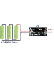
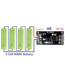
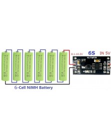
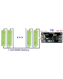
Szín: 1 cella (1S) - 1-8s 1,2V-9,6V NiMH NiCd újratölthető akkumulátortöltő töltőmodul kártya bemenet DC 5V
208 Ft 416 Ft
Product Name: 1-8s 1.2V-9.6V NiMH NiCd Rechargeable Battery Charger Charging Module Board Input DC 5V
Packing list:
1 PCS 1-8 cell NiCd/NiMH batteries Charger Module
(Please choose the parameters you need when purchasing)
Description:
1-Cell(1S) Version:
Input voltage : DC 4.5V-5.5V(Recommend DC 5V)
Charging voltage about : 1.35V-1.7V
Charging current about : 231mA-240mA
2-Cell(2S) Version:
Input voltage : DC 4.5V-5.5V(Recommend DC 5V)
Charging voltage about : 2.7V-3.4V
Charging current about :230mA-240mA
3-Cell(3S) Version:
Input voltage : DC 4.5V-5.5V(Recommend DC 5V)
Charging voltage about : 4.05V-5.1V
Charging current about : 230mA-240mA
4-Cell(4S) Version:
Input voltage : DC 4.5V-5.5V(Recommend DC 5V)
Charging voltage about : 5.7V-6.8V
Charging current about : 230mA-240mA
5-Cell(5S) Version:
Input voltage : DC 4.5V-5.5V(Recommend DC 5V)
Charging voltage about : 6.75V-8.5V
Charging current about : 230mA-240mA
6-Cell(6S) Version:
Input voltage : DC 4.5V-5.5V(Recommend DC 5V)
Charging voltage about : 8.1V-10.2V
Charging current about : 230mA-240mA
7-Cell(7S) Version:
Input voltage : DC 4.5V-5.5V(Recommend DC 5V)
Charging voltage about : 9.45V-11.9V
Charging current about : 190mA-210mA
8-Cell(8S) Version:
Input voltage : DC 4.5V-5.5V(Recommend DC 5V)
Charging voltage about : 10.8V-13.6V
Charging current about : 190mA-210mA
USB power protection
Short circuit protection and zero volt battery activation
Battery protection
Operating ambient temperature : -40° to 85°
Storage temperature : -65° to 125°
Size 30mm x 15mm x 4mm
Weight : 1.5g
Note: The output voltage cannot be measured with a multimeter without a battery. But can be observed with an oscilloscope.
Tip: If your battery is 1-3Cell, please choose a high current version: NIMHCRTA
Applications:
kids toys car
Digital Cameras
Solar charging
Bluetooth Applications
Audio equipment
Digital Camera
Electronic Dictionary
Portable Devices
Mobile power, UPS
1-8Cell Nickel Metal Hydride Battery Charger
1-8Cell NiCd Battery Charger
USB power protection:
When charging multiple batteries, the USB power supply needs to supply a large current. In order to ensure that no USB power is damaged, the NIUP11TA adds USB power protection. When the USB power supply voltage is pulled down to a certain threshold, reduce the charging current to protect the USB power supply. When the USB power supply voltage rises, adjust the charging current to the maximum value.
Short circuit protection and zero volt battery activation:
NIUP11TA can intelligently detect whether the output is short-circuited and indicate an error. The NIUP11TA allows long-term shorts in the output without damaging any circuitry and USB power, and the output is shorted and maintains low power consumption.
The NIUP11TA has a zero-volt battery activation function that determines a zero-volt battery when the short-circuit is detected for the first time after power-on. The horse activates the zero-volt battery, and the zero-volt battery activates and enters the normal charging process. If the zero volt battery is not activated, it will be judged to be a short circuit and the indicator light will start flashing.
Battery protection:
1) If the battery voltage is higher than 1.35V, the battery is considered to be close to full capacity. After plugging in, it will not be charged, and the indicator light will be extinguished to prevent the battery capacity from dropping due to the memory effect of the nickel-cadmium battery.
2) After the battery is connected, the number of battery packs will be judged. If the voltage is not within the corresponding range, charging will not be performed.
Charging process:
1) Battery insertion detection
When the charger is powered up, it will automatically detect the presence or absence of battery insertion. After detecting the zero-volt battery, it will be activated automatically. When the short-circuit is detected, an error will be indicated. If the number of battery packs is not matched with the circuit, an error will be reported. After the correct battery pack is inserted, normal charging will be performed.
2) Pre-charge
If the battery pack connected to the battery pack is less than 1V, it indicates that the battery is discharged too much. It needs to be activated after a small current is activated to prevent damage to the battery. Pre-charging requires a current of 100 mA and a fast charge when the single cell voltage is greater than 1V.
3) Fast charging
If the battery pack connected to the battery pack is already greater than 1V, it indicates that the battery has passed the precharge threshold and can be quickly charged. Fast charging requires current to be controlled at 250mA. The fast charging process should periodically detect the battery voltage and charging current, and detect the battery voltage -v or 0△V, and jump to make up the charging.
4) make up the charge
Fast charging has been used to charge the battery voltage to 1.3V or higher with a large current. If fast charging is used, the temperature of the battery will rise rapidly. It needs to be changed to a smaller current to make up the charge. At this time, the current is controlled at 200mA. Make up the charging time for 20 minutes, and then jump to trickle charging after the end of the charge.
5) trickle charging
In order to make up for the self-discharge of the battery, it will enter the trickle charge after the end of charging. The trickle charge current is 40mA. After entering the trickle charge, the indicator light has been extinguished. When the user removes the battery, it will enter the next charge cycle.
6) Battery take-out detection
When charging is entered, the system will continue to take the battery removal test. After detecting that the battery is removed, it will enter the next charging cycle. -
Szín: 2cellás (2S) - 1-8s 1,2V-9,6V NiMH NiCd újratölthető akkumulátortöltő töltő modul kártya bemenet DC 5V
208 Ft 416 Ft
Product Name: 1-8s 1.2V-9.6V NiMH NiCd Rechargeable Battery Charger Charging Module Board Input DC 5V
Packing list:
1 PCS 1-8 cell NiCd/NiMH batteries Charger Module
(Please choose the parameters you need when purchasing)
Description:
1-Cell(1S) Version:
Input voltage : DC 4.5V-5.5V(Recommend DC 5V)
Charging voltage about : 1.35V-1.7V
Charging current about : 231mA-240mA
2-Cell(2S) Version:
Input voltage : DC 4.5V-5.5V(Recommend DC 5V)
Charging voltage about : 2.7V-3.4V
Charging current about :230mA-240mA
3-Cell(3S) Version:
Input voltage : DC 4.5V-5.5V(Recommend DC 5V)
Charging voltage about : 4.05V-5.1V
Charging current about : 230mA-240mA
4-Cell(4S) Version:
Input voltage : DC 4.5V-5.5V(Recommend DC 5V)
Charging voltage about : 5.7V-6.8V
Charging current about : 230mA-240mA
5-Cell(5S) Version:
Input voltage : DC 4.5V-5.5V(Recommend DC 5V)
Charging voltage about : 6.75V-8.5V
Charging current about : 230mA-240mA
6-Cell(6S) Version:
Input voltage : DC 4.5V-5.5V(Recommend DC 5V)
Charging voltage about : 8.1V-10.2V
Charging current about : 230mA-240mA
7-Cell(7S) Version:
Input voltage : DC 4.5V-5.5V(Recommend DC 5V)
Charging voltage about : 9.45V-11.9V
Charging current about : 190mA-210mA
8-Cell(8S) Version:
Input voltage : DC 4.5V-5.5V(Recommend DC 5V)
Charging voltage about : 10.8V-13.6V
Charging current about : 190mA-210mA
USB power protection
Short circuit protection and zero volt battery activation
Battery protection
Operating ambient temperature : -40° to 85°
Storage temperature : -65° to 125°
Size 30mm x 15mm x 4mm
Weight : 1.5g
Note: The output voltage cannot be measured with a multimeter without a battery. But can be observed with an oscilloscope.
Tip: If your battery is 1-3Cell, please choose a high current version: NIMHCRTA
Applications:
kids toys car
Digital Cameras
Solar charging
Bluetooth Applications
Audio equipment
Digital Camera
Electronic Dictionary
Portable Devices
Mobile power, UPS
1-8Cell Nickel Metal Hydride Battery Charger
1-8Cell NiCd Battery Charger
USB power protection:
When charging multiple batteries, the USB power supply needs to supply a large current. In order to ensure that no USB power is damaged, the NIUP11TA adds USB power protection. When the USB power supply voltage is pulled down to a certain threshold, reduce the charging current to protect the USB power supply. When the USB power supply voltage rises, adjust the charging current to the maximum value.
Short circuit protection and zero volt battery activation:
NIUP11TA can intelligently detect whether the output is short-circuited and indicate an error. The NIUP11TA allows long-term shorts in the output without damaging any circuitry and USB power, and the output is shorted and maintains low power consumption.
The NIUP11TA has a zero-volt battery activation function that determines a zero-volt battery when the short-circuit is detected for the first time after power-on. The horse activates the zero-volt battery, and the zero-volt battery activates and enters the normal charging process. If the zero volt battery is not activated, it will be judged to be a short circuit and the indicator light will start flashing.
Battery protection:
1) If the battery voltage is higher than 1.35V, the battery is considered to be close to full capacity. After plugging in, it will not be charged, and the indicator light will be extinguished to prevent the battery capacity from dropping due to the memory effect of the nickel-cadmium battery.
2) After the battery is connected, the number of battery packs will be judged. If the voltage is not within the corresponding range, charging will not be performed.
Charging process:
1) Battery insertion detection
When the charger is powered up, it will automatically detect the presence or absence of battery insertion. After detecting the zero-volt battery, it will be activated automatically. When the short-circuit is detected, an error will be indicated. If the number of battery packs is not matched with the circuit, an error will be reported. After the correct battery pack is inserted, normal charging will be performed.
2) Pre-charge
If the battery pack connected to the battery pack is less than 1V, it indicates that the battery is discharged too much. It needs to be activated after a small current is activated to prevent damage to the battery. Pre-charging requires a current of 100 mA and a fast charge when the single cell voltage is greater than 1V.
3) Fast charging
If the battery pack connected to the battery pack is already greater than 1V, it indicates that the battery has passed the precharge threshold and can be quickly charged. Fast charging requires current to be controlled at 250mA. The fast charging process should periodically detect the battery voltage and charging current, and detect the battery voltage -v or 0△V, and jump to make up the charging.
4) make up the charge
Fast charging has been used to charge the battery voltage to 1.3V or higher with a large current. If fast charging is used, the temperature of the battery will rise rapidly. It needs to be changed to a smaller current to make up the charge. At this time, the current is controlled at 200mA. Make up the charging time for 20 minutes, and then jump to trickle charging after the end of the charge.
5) trickle charging
In order to make up for the self-discharge of the battery, it will enter the trickle charge after the end of charging. The trickle charge current is 40mA. After entering the trickle charge, the indicator light has been extinguished. When the user removes the battery, it will enter the next charge cycle.
6) Battery take-out detection
When charging is entered, the system will continue to take the battery removal test. After detecting that the battery is removed, it will enter the next charging cycle. -
Szín: 3 cellás (3S) - 1-8s 1,2V-9,6V NiMH NiCd újratölthető akkumulátortöltő töltő modul kártya bemenet DC 5V
208 Ft 416 Ft
Product Name: 1-8s 1.2V-9.6V NiMH NiCd Rechargeable Battery Charger Charging Module Board Input DC 5V
Packing list:
1 PCS 1-8 cell NiCd/NiMH batteries Charger Module
(Please choose the parameters you need when purchasing)
Description:
1-Cell(1S) Version:
Input voltage : DC 4.5V-5.5V(Recommend DC 5V)
Charging voltage about : 1.35V-1.7V
Charging current about : 231mA-240mA
2-Cell(2S) Version:
Input voltage : DC 4.5V-5.5V(Recommend DC 5V)
Charging voltage about : 2.7V-3.4V
Charging current about :230mA-240mA
3-Cell(3S) Version:
Input voltage : DC 4.5V-5.5V(Recommend DC 5V)
Charging voltage about : 4.05V-5.1V
Charging current about : 230mA-240mA
4-Cell(4S) Version:
Input voltage : DC 4.5V-5.5V(Recommend DC 5V)
Charging voltage about : 5.7V-6.8V
Charging current about : 230mA-240mA
5-Cell(5S) Version:
Input voltage : DC 4.5V-5.5V(Recommend DC 5V)
Charging voltage about : 6.75V-8.5V
Charging current about : 230mA-240mA
6-Cell(6S) Version:
Input voltage : DC 4.5V-5.5V(Recommend DC 5V)
Charging voltage about : 8.1V-10.2V
Charging current about : 230mA-240mA
7-Cell(7S) Version:
Input voltage : DC 4.5V-5.5V(Recommend DC 5V)
Charging voltage about : 9.45V-11.9V
Charging current about : 190mA-210mA
8-Cell(8S) Version:
Input voltage : DC 4.5V-5.5V(Recommend DC 5V)
Charging voltage about : 10.8V-13.6V
Charging current about : 190mA-210mA
USB power protection
Short circuit protection and zero volt battery activation
Battery protection
Operating ambient temperature : -40° to 85°
Storage temperature : -65° to 125°
Size 30mm x 15mm x 4mm
Weight : 1.5g
Note: The output voltage cannot be measured with a multimeter without a battery. But can be observed with an oscilloscope.
Tip: If your battery is 1-3Cell, please choose a high current version: NIMHCRTA
Applications:
kids toys car
Digital Cameras
Solar charging
Bluetooth Applications
Audio equipment
Digital Camera
Electronic Dictionary
Portable Devices
Mobile power, UPS
1-8Cell Nickel Metal Hydride Battery Charger
1-8Cell NiCd Battery Charger
USB power protection:
When charging multiple batteries, the USB power supply needs to supply a large current. In order to ensure that no USB power is damaged, the NIUP11TA adds USB power protection. When the USB power supply voltage is pulled down to a certain threshold, reduce the charging current to protect the USB power supply. When the USB power supply voltage rises, adjust the charging current to the maximum value.
Short circuit protection and zero volt battery activation:
NIUP11TA can intelligently detect whether the output is short-circuited and indicate an error. The NIUP11TA allows long-term shorts in the output without damaging any circuitry and USB power, and the output is shorted and maintains low power consumption.
The NIUP11TA has a zero-volt battery activation function that determines a zero-volt battery when the short-circuit is detected for the first time after power-on. The horse activates the zero-volt battery, and the zero-volt battery activates and enters the normal charging process. If the zero volt battery is not activated, it will be judged to be a short circuit and the indicator light will start flashing.
Battery protection:
1) If the battery voltage is higher than 1.35V, the battery is considered to be close to full capacity. After plugging in, it will not be charged, and the indicator light will be extinguished to prevent the battery capacity from dropping due to the memory effect of the nickel-cadmium battery.
2) After the battery is connected, the number of battery packs will be judged. If the voltage is not within the corresponding range, charging will not be performed.
Charging process:
1) Battery insertion detection
When the charger is powered up, it will automatically detect the presence or absence of battery insertion. After detecting the zero-volt battery, it will be activated automatically. When the short-circuit is detected, an error will be indicated. If the number of battery packs is not matched with the circuit, an error will be reported. After the correct battery pack is inserted, normal charging will be performed.
2) Pre-charge
If the battery pack connected to the battery pack is less than 1V, it indicates that the battery is discharged too much. It needs to be activated after a small current is activated to prevent damage to the battery. Pre-charging requires a current of 100 mA and a fast charge when the single cell voltage is greater than 1V.
3) Fast charging
If the battery pack connected to the battery pack is already greater than 1V, it indicates that the battery has passed the precharge threshold and can be quickly charged. Fast charging requires current to be controlled at 250mA. The fast charging process should periodically detect the battery voltage and charging current, and detect the battery voltage -v or 0△V, and jump to make up the charging.
4) make up the charge
Fast charging has been used to charge the battery voltage to 1.3V or higher with a large current. If fast charging is used, the temperature of the battery will rise rapidly. It needs to be changed to a smaller current to make up the charge. At this time, the current is controlled at 200mA. Make up the charging time for 20 minutes, and then jump to trickle charging after the end of the charge.
5) trickle charging
In order to make up for the self-discharge of the battery, it will enter the trickle charge after the end of charging. The trickle charge current is 40mA. After entering the trickle charge, the indicator light has been extinguished. When the user removes the battery, it will enter the next charge cycle.
6) Battery take-out detection
When charging is entered, the system will continue to take the battery removal test. After detecting that the battery is removed, it will enter the next charging cycle. -
Szín: 4 cellás (4S) - 1-8s 1,2V-9,6V NiMH NiCd újratölthető akkumulátortöltő töltő modul kártya bemenet DC 5V
208 Ft 416 Ft
Product Name: 1-8s 1.2V-9.6V NiMH NiCd Rechargeable Battery Charger Charging Module Board Input DC 5V
Packing list:
1 PCS 1-8 cell NiCd/NiMH batteries Charger Module
(Please choose the parameters you need when purchasing)
Description:
1-Cell(1S) Version:
Input voltage : DC 4.5V-5.5V(Recommend DC 5V)
Charging voltage about : 1.35V-1.7V
Charging current about : 231mA-240mA
2-Cell(2S) Version:
Input voltage : DC 4.5V-5.5V(Recommend DC 5V)
Charging voltage about : 2.7V-3.4V
Charging current about :230mA-240mA
3-Cell(3S) Version:
Input voltage : DC 4.5V-5.5V(Recommend DC 5V)
Charging voltage about : 4.05V-5.1V
Charging current about : 230mA-240mA
4-Cell(4S) Version:
Input voltage : DC 4.5V-5.5V(Recommend DC 5V)
Charging voltage about : 5.7V-6.8V
Charging current about : 230mA-240mA
5-Cell(5S) Version:
Input voltage : DC 4.5V-5.5V(Recommend DC 5V)
Charging voltage about : 6.75V-8.5V
Charging current about : 230mA-240mA
6-Cell(6S) Version:
Input voltage : DC 4.5V-5.5V(Recommend DC 5V)
Charging voltage about : 8.1V-10.2V
Charging current about : 230mA-240mA
7-Cell(7S) Version:
Input voltage : DC 4.5V-5.5V(Recommend DC 5V)
Charging voltage about : 9.45V-11.9V
Charging current about : 190mA-210mA
8-Cell(8S) Version:
Input voltage : DC 4.5V-5.5V(Recommend DC 5V)
Charging voltage about : 10.8V-13.6V
Charging current about : 190mA-210mA
USB power protection
Short circuit protection and zero volt battery activation
Battery protection
Operating ambient temperature : -40° to 85°
Storage temperature : -65° to 125°
Size 30mm x 15mm x 4mm
Weight : 1.5g
Note: The output voltage cannot be measured with a multimeter without a battery. But can be observed with an oscilloscope.
Tip: If your battery is 1-3Cell, please choose a high current version: NIMHCRTA
Applications:
kids toys car
Digital Cameras
Solar charging
Bluetooth Applications
Audio equipment
Digital Camera
Electronic Dictionary
Portable Devices
Mobile power, UPS
1-8Cell Nickel Metal Hydride Battery Charger
1-8Cell NiCd Battery Charger
USB power protection:
When charging multiple batteries, the USB power supply needs to supply a large current. In order to ensure that no USB power is damaged, the NIUP11TA adds USB power protection. When the USB power supply voltage is pulled down to a certain threshold, reduce the charging current to protect the USB power supply. When the USB power supply voltage rises, adjust the charging current to the maximum value.
Short circuit protection and zero volt battery activation:
NIUP11TA can intelligently detect whether the output is short-circuited and indicate an error. The NIUP11TA allows long-term shorts in the output without damaging any circuitry and USB power, and the output is shorted and maintains low power consumption.
The NIUP11TA has a zero-volt battery activation function that determines a zero-volt battery when the short-circuit is detected for the first time after power-on. The horse activates the zero-volt battery, and the zero-volt battery activates and enters the normal charging process. If the zero volt battery is not activated, it will be judged to be a short circuit and the indicator light will start flashing.
Battery protection:
1) If the battery voltage is higher than 1.35V, the battery is considered to be close to full capacity. After plugging in, it will not be charged, and the indicator light will be extinguished to prevent the battery capacity from dropping due to the memory effect of the nickel-cadmium battery.
2) After the battery is connected, the number of battery packs will be judged. If the voltage is not within the corresponding range, charging will not be performed.
Charging process:
1) Battery insertion detection
When the charger is powered up, it will automatically detect the presence or absence of battery insertion. After detecting the zero-volt battery, it will be activated automatically. When the short-circuit is detected, an error will be indicated. If the number of battery packs is not matched with the circuit, an error will be reported. After the correct battery pack is inserted, normal charging will be performed.
2) Pre-charge
If the battery pack connected to the battery pack is less than 1V, it indicates that the battery is discharged too much. It needs to be activated after a small current is activated to prevent damage to the battery. Pre-charging requires a current of 100 mA and a fast charge when the single cell voltage is greater than 1V.
3) Fast charging
If the battery pack connected to the battery pack is already greater than 1V, it indicates that the battery has passed the precharge threshold and can be quickly charged. Fast charging requires current to be controlled at 250mA. The fast charging process should periodically detect the battery voltage and charging current, and detect the battery voltage -v or 0△V, and jump to make up the charging.
4) make up the charge
Fast charging has been used to charge the battery voltage to 1.3V or higher with a large current. If fast charging is used, the temperature of the battery will rise rapidly. It needs to be changed to a smaller current to make up the charge. At this time, the current is controlled at 200mA. Make up the charging time for 20 minutes, and then jump to trickle charging after the end of the charge.
5) trickle charging
In order to make up for the self-discharge of the battery, it will enter the trickle charge after the end of charging. The trickle charge current is 40mA. After entering the trickle charge, the indicator light has been extinguished. When the user removes the battery, it will enter the next charge cycle.
6) Battery take-out detection
When charging is entered, the system will continue to take the battery removal test. After detecting that the battery is removed, it will enter the next charging cycle. -
Szín: 5 cellás (5S) - 1-8s 1,2V-9,6V NiMH NiCd újratölthető akkumulátortöltő töltő modul kártya bemenet DC 5V
208 Ft 416 Ft
Product Name: 1-8s 1.2V-9.6V NiMH NiCd Rechargeable Battery Charger Charging Module Board Input DC 5V
Packing list:
1 PCS 1-8 cell NiCd/NiMH batteries Charger Module
(Please choose the parameters you need when purchasing)
Description:
1-Cell(1S) Version:
Input voltage : DC 4.5V-5.5V(Recommend DC 5V)
Charging voltage about : 1.35V-1.7V
Charging current about : 231mA-240mA
2-Cell(2S) Version:
Input voltage : DC 4.5V-5.5V(Recommend DC 5V)
Charging voltage about : 2.7V-3.4V
Charging current about :230mA-240mA
3-Cell(3S) Version:
Input voltage : DC 4.5V-5.5V(Recommend DC 5V)
Charging voltage about : 4.05V-5.1V
Charging current about : 230mA-240mA
4-Cell(4S) Version:
Input voltage : DC 4.5V-5.5V(Recommend DC 5V)
Charging voltage about : 5.7V-6.8V
Charging current about : 230mA-240mA
5-Cell(5S) Version:
Input voltage : DC 4.5V-5.5V(Recommend DC 5V)
Charging voltage about : 6.75V-8.5V
Charging current about : 230mA-240mA
6-Cell(6S) Version:
Input voltage : DC 4.5V-5.5V(Recommend DC 5V)
Charging voltage about : 8.1V-10.2V
Charging current about : 230mA-240mA
7-Cell(7S) Version:
Input voltage : DC 4.5V-5.5V(Recommend DC 5V)
Charging voltage about : 9.45V-11.9V
Charging current about : 190mA-210mA
8-Cell(8S) Version:
Input voltage : DC 4.5V-5.5V(Recommend DC 5V)
Charging voltage about : 10.8V-13.6V
Charging current about : 190mA-210mA
USB power protection
Short circuit protection and zero volt battery activation
Battery protection
Operating ambient temperature : -40° to 85°
Storage temperature : -65° to 125°
Size 30mm x 15mm x 4mm
Weight : 1.5g
Note: The output voltage cannot be measured with a multimeter without a battery. But can be observed with an oscilloscope.
Tip: If your battery is 1-3Cell, please choose a high current version: NIMHCRTA
Applications:
kids toys car
Digital Cameras
Solar charging
Bluetooth Applications
Audio equipment
Digital Camera
Electronic Dictionary
Portable Devices
Mobile power, UPS
1-8Cell Nickel Metal Hydride Battery Charger
1-8Cell NiCd Battery Charger
USB power protection:
When charging multiple batteries, the USB power supply needs to supply a large current. In order to ensure that no USB power is damaged, the NIUP11TA adds USB power protection. When the USB power supply voltage is pulled down to a certain threshold, reduce the charging current to protect the USB power supply. When the USB power supply voltage rises, adjust the charging current to the maximum value.
Short circuit protection and zero volt battery activation:
NIUP11TA can intelligently detect whether the output is short-circuited and indicate an error. The NIUP11TA allows long-term shorts in the output without damaging any circuitry and USB power, and the output is shorted and maintains low power consumption.
The NIUP11TA has a zero-volt battery activation function that determines a zero-volt battery when the short-circuit is detected for the first time after power-on. The horse activates the zero-volt battery, and the zero-volt battery activates and enters the normal charging process. If the zero volt battery is not activated, it will be judged to be a short circuit and the indicator light will start flashing.
Battery protection:
1) If the battery voltage is higher than 1.35V, the battery is considered to be close to full capacity. After plugging in, it will not be charged, and the indicator light will be extinguished to prevent the battery capacity from dropping due to the memory effect of the nickel-cadmium battery.
2) After the battery is connected, the number of battery packs will be judged. If the voltage is not within the corresponding range, charging will not be performed.
Charging process:
1) Battery insertion detection
When the charger is powered up, it will automatically detect the presence or absence of battery insertion. After detecting the zero-volt battery, it will be activated automatically. When the short-circuit is detected, an error will be indicated. If the number of battery packs is not matched with the circuit, an error will be reported. After the correct battery pack is inserted, normal charging will be performed.
2) Pre-charge
If the battery pack connected to the battery pack is less than 1V, it indicates that the battery is discharged too much. It needs to be activated after a small current is activated to prevent damage to the battery. Pre-charging requires a current of 100 mA and a fast charge when the single cell voltage is greater than 1V.
3) Fast charging
If the battery pack connected to the battery pack is already greater than 1V, it indicates that the battery has passed the precharge threshold and can be quickly charged. Fast charging requires current to be controlled at 250mA. The fast charging process should periodically detect the battery voltage and charging current, and detect the battery voltage -v or 0△V, and jump to make up the charging.
4) make up the charge
Fast charging has been used to charge the battery voltage to 1.3V or higher with a large current. If fast charging is used, the temperature of the battery will rise rapidly. It needs to be changed to a smaller current to make up the charge. At this time, the current is controlled at 200mA. Make up the charging time for 20 minutes, and then jump to trickle charging after the end of the charge.
5) trickle charging
In order to make up for the self-discharge of the battery, it will enter the trickle charge after the end of charging. The trickle charge current is 40mA. After entering the trickle charge, the indicator light has been extinguished. When the user removes the battery, it will enter the next charge cycle.
6) Battery take-out detection
When charging is entered, the system will continue to take the battery removal test. After detecting that the battery is removed, it will enter the next charging cycle. -
Szín: 6 cellás (6S) - 1-8s 1,2V-9,6V NiMH NiCd újratölthető akkumulátortöltő töltő modul kártya bemenet DC 5V
208 Ft 416 Ft
Product Name: 1-8s 1.2V-9.6V NiMH NiCd Rechargeable Battery Charger Charging Module Board Input DC 5V
Packing list:
1 PCS 1-8 cell NiCd/NiMH batteries Charger Module
(Please choose the parameters you need when purchasing)
Description:
1-Cell(1S) Version:
Input voltage : DC 4.5V-5.5V(Recommend DC 5V)
Charging voltage about : 1.35V-1.7V
Charging current about : 231mA-240mA
2-Cell(2S) Version:
Input voltage : DC 4.5V-5.5V(Recommend DC 5V)
Charging voltage about : 2.7V-3.4V
Charging current about :230mA-240mA
3-Cell(3S) Version:
Input voltage : DC 4.5V-5.5V(Recommend DC 5V)
Charging voltage about : 4.05V-5.1V
Charging current about : 230mA-240mA
4-Cell(4S) Version:
Input voltage : DC 4.5V-5.5V(Recommend DC 5V)
Charging voltage about : 5.7V-6.8V
Charging current about : 230mA-240mA
5-Cell(5S) Version:
Input voltage : DC 4.5V-5.5V(Recommend DC 5V)
Charging voltage about : 6.75V-8.5V
Charging current about : 230mA-240mA
6-Cell(6S) Version:
Input voltage : DC 4.5V-5.5V(Recommend DC 5V)
Charging voltage about : 8.1V-10.2V
Charging current about : 230mA-240mA
7-Cell(7S) Version:
Input voltage : DC 4.5V-5.5V(Recommend DC 5V)
Charging voltage about : 9.45V-11.9V
Charging current about : 190mA-210mA
8-Cell(8S) Version:
Input voltage : DC 4.5V-5.5V(Recommend DC 5V)
Charging voltage about : 10.8V-13.6V
Charging current about : 190mA-210mA
USB power protection
Short circuit protection and zero volt battery activation
Battery protection
Operating ambient temperature : -40° to 85°
Storage temperature : -65° to 125°
Size 30mm x 15mm x 4mm
Weight : 1.5g
Note: The output voltage cannot be measured with a multimeter without a battery. But can be observed with an oscilloscope.
Tip: If your battery is 1-3Cell, please choose a high current version: NIMHCRTA
Applications:
kids toys car
Digital Cameras
Solar charging
Bluetooth Applications
Audio equipment
Digital Camera
Electronic Dictionary
Portable Devices
Mobile power, UPS
1-8Cell Nickel Metal Hydride Battery Charger
1-8Cell NiCd Battery Charger
USB power protection:
When charging multiple batteries, the USB power supply needs to supply a large current. In order to ensure that no USB power is damaged, the NIUP11TA adds USB power protection. When the USB power supply voltage is pulled down to a certain threshold, reduce the charging current to protect the USB power supply. When the USB power supply voltage rises, adjust the charging current to the maximum value.
Short circuit protection and zero volt battery activation:
NIUP11TA can intelligently detect whether the output is short-circuited and indicate an error. The NIUP11TA allows long-term shorts in the output without damaging any circuitry and USB power, and the output is shorted and maintains low power consumption.
The NIUP11TA has a zero-volt battery activation function that determines a zero-volt battery when the short-circuit is detected for the first time after power-on. The horse activates the zero-volt battery, and the zero-volt battery activates and enters the normal charging process. If the zero volt battery is not activated, it will be judged to be a short circuit and the indicator light will start flashing.
Battery protection:
1) If the battery voltage is higher than 1.35V, the battery is considered to be close to full capacity. After plugging in, it will not be charged, and the indicator light will be extinguished to prevent the battery capacity from dropping due to the memory effect of the nickel-cadmium battery.
2) After the battery is connected, the number of battery packs will be judged. If the voltage is not within the corresponding range, charging will not be performed.
Charging process:
1) Battery insertion detection
When the charger is powered up, it will automatically detect the presence or absence of battery insertion. After detecting the zero-volt battery, it will be activated automatically. When the short-circuit is detected, an error will be indicated. If the number of battery packs is not matched with the circuit, an error will be reported. After the correct battery pack is inserted, normal charging will be performed.
2) Pre-charge
If the battery pack connected to the battery pack is less than 1V, it indicates that the battery is discharged too much. It needs to be activated after a small current is activated to prevent damage to the battery. Pre-charging requires a current of 100 mA and a fast charge when the single cell voltage is greater than 1V.
3) Fast charging
If the battery pack connected to the battery pack is already greater than 1V, it indicates that the battery has passed the precharge threshold and can be quickly charged. Fast charging requires current to be controlled at 250mA. The fast charging process should periodically detect the battery voltage and charging current, and detect the battery voltage -v or 0△V, and jump to make up the charging.
4) make up the charge
Fast charging has been used to charge the battery voltage to 1.3V or higher with a large current. If fast charging is used, the temperature of the battery will rise rapidly. It needs to be changed to a smaller current to make up the charge. At this time, the current is controlled at 200mA. Make up the charging time for 20 minutes, and then jump to trickle charging after the end of the charge.
5) trickle charging
In order to make up for the self-discharge of the battery, it will enter the trickle charge after the end of charging. The trickle charge current is 40mA. After entering the trickle charge, the indicator light has been extinguished. When the user removes the battery, it will enter the next charge cycle.
6) Battery take-out detection
When charging is entered, the system will continue to take the battery removal test. After detecting that the battery is removed, it will enter the next charging cycle. -
Szín: 7 cellás (7S) - 1-8s 1,2V-9,6V NiMH NiCd újratölthető akkumulátortöltő töltő modul kártya bemenet DC 5V
208 Ft 416 Ft
Product Name: 1-8s 1.2V-9.6V NiMH NiCd Rechargeable Battery Charger Charging Module Board Input DC 5V
Packing list:
1 PCS 1-8 cell NiCd/NiMH batteries Charger Module
(Please choose the parameters you need when purchasing)
Description:
1-Cell(1S) Version:
Input voltage : DC 4.5V-5.5V(Recommend DC 5V)
Charging voltage about : 1.35V-1.7V
Charging current about : 231mA-240mA
2-Cell(2S) Version:
Input voltage : DC 4.5V-5.5V(Recommend DC 5V)
Charging voltage about : 2.7V-3.4V
Charging current about :230mA-240mA
3-Cell(3S) Version:
Input voltage : DC 4.5V-5.5V(Recommend DC 5V)
Charging voltage about : 4.05V-5.1V
Charging current about : 230mA-240mA
4-Cell(4S) Version:
Input voltage : DC 4.5V-5.5V(Recommend DC 5V)
Charging voltage about : 5.7V-6.8V
Charging current about : 230mA-240mA
5-Cell(5S) Version:
Input voltage : DC 4.5V-5.5V(Recommend DC 5V)
Charging voltage about : 6.75V-8.5V
Charging current about : 230mA-240mA
6-Cell(6S) Version:
Input voltage : DC 4.5V-5.5V(Recommend DC 5V)
Charging voltage about : 8.1V-10.2V
Charging current about : 230mA-240mA
7-Cell(7S) Version:
Input voltage : DC 4.5V-5.5V(Recommend DC 5V)
Charging voltage about : 9.45V-11.9V
Charging current about : 190mA-210mA
8-Cell(8S) Version:
Input voltage : DC 4.5V-5.5V(Recommend DC 5V)
Charging voltage about : 10.8V-13.6V
Charging current about : 190mA-210mA
USB power protection
Short circuit protection and zero volt battery activation
Battery protection
Operating ambient temperature : -40° to 85°
Storage temperature : -65° to 125°
Size 30mm x 15mm x 4mm
Weight : 1.5g
Note: The output voltage cannot be measured with a multimeter without a battery. But can be observed with an oscilloscope.
Tip: If your battery is 1-3Cell, please choose a high current version: NIMHCRTA
Applications:
kids toys car
Digital Cameras
Solar charging
Bluetooth Applications
Audio equipment
Digital Camera
Electronic Dictionary
Portable Devices
Mobile power, UPS
1-8Cell Nickel Metal Hydride Battery Charger
1-8Cell NiCd Battery Charger
USB power protection:
When charging multiple batteries, the USB power supply needs to supply a large current. In order to ensure that no USB power is damaged, the NIUP11TA adds USB power protection. When the USB power supply voltage is pulled down to a certain threshold, reduce the charging current to protect the USB power supply. When the USB power supply voltage rises, adjust the charging current to the maximum value.
Short circuit protection and zero volt battery activation:
NIUP11TA can intelligently detect whether the output is short-circuited and indicate an error. The NIUP11TA allows long-term shorts in the output without damaging any circuitry and USB power, and the output is shorted and maintains low power consumption.
The NIUP11TA has a zero-volt battery activation function that determines a zero-volt battery when the short-circuit is detected for the first time after power-on. The horse activates the zero-volt battery, and the zero-volt battery activates and enters the normal charging process. If the zero volt battery is not activated, it will be judged to be a short circuit and the indicator light will start flashing.
Battery protection:
1) If the battery voltage is higher than 1.35V, the battery is considered to be close to full capacity. After plugging in, it will not be charged, and the indicator light will be extinguished to prevent the battery capacity from dropping due to the memory effect of the nickel-cadmium battery.
2) After the battery is connected, the number of battery packs will be judged. If the voltage is not within the corresponding range, charging will not be performed.
Charging process:
1) Battery insertion detection
When the charger is powered up, it will automatically detect the presence or absence of battery insertion. After detecting the zero-volt battery, it will be activated automatically. When the short-circuit is detected, an error will be indicated. If the number of battery packs is not matched with the circuit, an error will be reported. After the correct battery pack is inserted, normal charging will be performed.
2) Pre-charge
If the battery pack connected to the battery pack is less than 1V, it indicates that the battery is discharged too much. It needs to be activated after a small current is activated to prevent damage to the battery. Pre-charging requires a current of 100 mA and a fast charge when the single cell voltage is greater than 1V.
3) Fast charging
If the battery pack connected to the battery pack is already greater than 1V, it indicates that the battery has passed the precharge threshold and can be quickly charged. Fast charging requires current to be controlled at 250mA. The fast charging process should periodically detect the battery voltage and charging current, and detect the battery voltage -v or 0△V, and jump to make up the charging.
4) make up the charge
Fast charging has been used to charge the battery voltage to 1.3V or higher with a large current. If fast charging is used, the temperature of the battery will rise rapidly. It needs to be changed to a smaller current to make up the charge. At this time, the current is controlled at 200mA. Make up the charging time for 20 minutes, and then jump to trickle charging after the end of the charge.
5) trickle charging
In order to make up for the self-discharge of the battery, it will enter the trickle charge after the end of charging. The trickle charge current is 40mA. After entering the trickle charge, the indicator light has been extinguished. When the user removes the battery, it will enter the next charge cycle.
6) Battery take-out detection
When charging is entered, the system will continue to take the battery removal test. After detecting that the battery is removed, it will enter the next charging cycle. -
Szín: 8 Cell (8S) - 1-8s 1,2V-9,6V NiMH NiCd újratölthető akkumulátortöltő töltő modul kártya bemenet DC 5V
208 Ft 416 Ft
Product Name: 1-8s 1.2V-9.6V NiMH NiCd Rechargeable Battery Charger Charging Module Board Input DC 5V
Packing list:
1 PCS 1-8 cell NiCd/NiMH batteries Charger Module
(Please choose the parameters you need when purchasing)
Description:
1-Cell(1S) Version:
Input voltage : DC 4.5V-5.5V(Recommend DC 5V)
Charging voltage about : 1.35V-1.7V
Charging current about : 231mA-240mA
2-Cell(2S) Version:
Input voltage : DC 4.5V-5.5V(Recommend DC 5V)
Charging voltage about : 2.7V-3.4V
Charging current about :230mA-240mA
3-Cell(3S) Version:
Input voltage : DC 4.5V-5.5V(Recommend DC 5V)
Charging voltage about : 4.05V-5.1V
Charging current about : 230mA-240mA
4-Cell(4S) Version:
Input voltage : DC 4.5V-5.5V(Recommend DC 5V)
Charging voltage about : 5.7V-6.8V
Charging current about : 230mA-240mA
5-Cell(5S) Version:
Input voltage : DC 4.5V-5.5V(Recommend DC 5V)
Charging voltage about : 6.75V-8.5V
Charging current about : 230mA-240mA
6-Cell(6S) Version:
Input voltage : DC 4.5V-5.5V(Recommend DC 5V)
Charging voltage about : 8.1V-10.2V
Charging current about : 230mA-240mA
7-Cell(7S) Version:
Input voltage : DC 4.5V-5.5V(Recommend DC 5V)
Charging voltage about : 9.45V-11.9V
Charging current about : 190mA-210mA
8-Cell(8S) Version:
Input voltage : DC 4.5V-5.5V(Recommend DC 5V)
Charging voltage about : 10.8V-13.6V
Charging current about : 190mA-210mA
USB power protection
Short circuit protection and zero volt battery activation
Battery protection
Operating ambient temperature : -40° to 85°
Storage temperature : -65° to 125°
Size 30mm x 15mm x 4mm
Weight : 1.5g
Note: The output voltage cannot be measured with a multimeter without a battery. But can be observed with an oscilloscope.
Tip: If your battery is 1-3Cell, please choose a high current version: NIMHCRTA
Applications:
kids toys car
Digital Cameras
Solar charging
Bluetooth Applications
Audio equipment
Digital Camera
Electronic Dictionary
Portable Devices
Mobile power, UPS
1-8Cell Nickel Metal Hydride Battery Charger
1-8Cell NiCd Battery Charger
USB power protection:
When charging multiple batteries, the USB power supply needs to supply a large current. In order to ensure that no USB power is damaged, the NIUP11TA adds USB power protection. When the USB power supply voltage is pulled down to a certain threshold, reduce the charging current to protect the USB power supply. When the USB power supply voltage rises, adjust the charging current to the maximum value.
Short circuit protection and zero volt battery activation:
NIUP11TA can intelligently detect whether the output is short-circuited and indicate an error. The NIUP11TA allows long-term shorts in the output without damaging any circuitry and USB power, and the output is shorted and maintains low power consumption.
The NIUP11TA has a zero-volt battery activation function that determines a zero-volt battery when the short-circuit is detected for the first time after power-on. The horse activates the zero-volt battery, and the zero-volt battery activates and enters the normal charging process. If the zero volt battery is not activated, it will be judged to be a short circuit and the indicator light will start flashing.
Battery protection:
1) If the battery voltage is higher than 1.35V, the battery is considered to be close to full capacity. After plugging in, it will not be charged, and the indicator light will be extinguished to prevent the battery capacity from dropping due to the memory effect of the nickel-cadmium battery.
2) After the battery is connected, the number of battery packs will be judged. If the voltage is not within the corresponding range, charging will not be performed.
Charging process:
1) Battery insertion detection
When the charger is powered up, it will automatically detect the presence or absence of battery insertion. After detecting the zero-volt battery, it will be activated automatically. When the short-circuit is detected, an error will be indicated. If the number of battery packs is not matched with the circuit, an error will be reported. After the correct battery pack is inserted, normal charging will be performed.
2) Pre-charge
If the battery pack connected to the battery pack is less than 1V, it indicates that the battery is discharged too much. It needs to be activated after a small current is activated to prevent damage to the battery. Pre-charging requires a current of 100 mA and a fast charge when the single cell voltage is greater than 1V.
3) Fast charging
If the battery pack connected to the battery pack is already greater than 1V, it indicates that the battery has passed the precharge threshold and can be quickly charged. Fast charging requires current to be controlled at 250mA. The fast charging process should periodically detect the battery voltage and charging current, and detect the battery voltage -v or 0△V, and jump to make up the charging.
4) make up the charge
Fast charging has been used to charge the battery voltage to 1.3V or higher with a large current. If fast charging is used, the temperature of the battery will rise rapidly. It needs to be changed to a smaller current to make up the charge. At this time, the current is controlled at 200mA. Make up the charging time for 20 minutes, and then jump to trickle charging after the end of the charge.
5) trickle charging
In order to make up for the self-discharge of the battery, it will enter the trickle charge after the end of charging. The trickle charge current is 40mA. After entering the trickle charge, the indicator light has been extinguished. When the user removes the battery, it will enter the next charge cycle.
6) Battery take-out detection
When charging is entered, the system will continue to take the battery removal test. After detecting that the battery is removed, it will enter the next charging cycle. -
USB-RS485 busz átalakító modul CH340 Ipari minőségű IC SP485 Arduino UNO NANO PLC MCU Modbus relé kártyához
302 Ft 604 FtProduct Name: USB to RS485 Bus Converter Module CH340 Industrial grade IC SP232 for Arduiuo UNO NANO PLC MCU Modbus Relay Board
Packing list:
1 PCS CH340E SP485 USB to RS485 Converter
Description:
This is Industrial grade SP485 USB TO RS485 Converter
The USB driver IC is CH340E, stable performance, fully compatible with USB1.1,USB2.0,USB3.0 , baud rate up to 256 kbps;
The RS485 bus IC is SP485,this is Industrial grade RS485 conversion IC
USB to RS485 serial port, 4 pin pin assignment as below : 5V GND A B-
Uses : CH340 replace FT232 CP2102 PL2303 for PLC PTZ RS485 MCU etc. RS485 Bus Device
Size : 36 x 16 x 12mm
Weight : 8g
Supports the following Windows OSes:
Windows 98SE
Windows ME
Windows 2000 SP4
Windows XP SP2 and above (32 & 64 bit)
Windows Server 2003 (32 & 64 bit)
Windows Server 2008 / 2008 R2 (32 & 64 bit)
Windows Vista (32 & 64 bit)
Windows 7 (32 & 64 bit)
Windows 8
Windows 8.1
Windows 10
Linux OS
MAC OS
Application :
RS485 Bus device
5V RS485 device(CE035 NTA8A01 R46CA01 R46CA01 R413D08 etc.)
12V/24V RS485 device (CE040 R421A08 R4D1C32 R421B16 R4D3B16 etc.)
PLC Modubs device
Camera PTZ
MODEM
Computer communication terminal
Remote control, remote measurement system;
Wireless meter ;
Smart Home,Home Automation ,Wiser Home;
Access control ;
Identification system ;
Data collection;
IT household appliance ;
Intelligence household appliance;
Baby monitoring system; -
6A DC 3V 3.3V 3.7V 5V Elektronikus kapcsolóretesz Bistabil önzáró kioldótábla LED-motor-meghajtóhoz Solar Lítium
177 Ft 354 FtProduct Name: 6A DC 3V 3.3V 3.7V 5V Electronic Switch Latch Bistable Self-locking Trigger Board for LED Motor Instrumentation Lithium battery
Packing list:
1 PCS IO15B01 2.5-6V 5A LED Motor Flip-Flop Latch Switch Module
Description:
Falling edge - triggered. Initial state after power no voltage output, once triggered, output terminal output the power supply votage, after once again trigger the output terminal no voltaged output, and so on.
Low standby power consumption, high output power.
Electrical parameters:
Power supply voltage:DC 2.5V-6V
Standby current:less than 10uA
Driver IC is Dual P-channel MOSFET MEM2313,Maximum drive current is 6A
Allowing continuous output current:
5A(5V-6V)
4A(3.7V-5V)
2A(2.5V-3.7V)
Pin pitch 2.54mm.
Size:15.5mm x 10mm x 2.5mm.
Weight : 0.5g
Note:inductive load, the load to the appropriate freewheeling diode in parallel to avoid damaged to the switching elements of the circuit.
Pin description:
Vo:output;
Vi:power supply;
G:power ground.
T:trigger signal input terminal;
Applications:
MCU Development Board
Motor
mobile power
LED Lighting
5V Relay
esp8266 WIFI MODULE
315M 433M Wireless remote controller
-
DC 80V 72V 64V 60V 48V 36V 24V – 12V HV DC-DC Buck Leléptető feszültségszabályozó kártya tápegység modul
404 Ft 808 FtProduct Name : DC 80V 72V 64V 60V 48V 36V 24V to 12V HV DC-DC Buck Step-Down Converter Voltage Regulator Board Power Supply Module
Packing list:
1 PCS HV DD8024TB_12V 14-80V to 12V DC-DC Converter Buck Module
Description:
Input voltage 14~80V,output 12V
Maximum output current 0.75A
DC-DC high-voltage Step-Down Converter module working frequency 150KHz.
Maximum conversion efficiency is 85% .
Quiescent current: about 2.5mA
Operating Temperature : –40°C to 85°C
Size : 59 x 30 x 16mm
Weight : 15.5g;
Features :
1 Input reverse polarity protection
2 TVS overvoltage protection
3 High frequency filter capacitor
4 High Q value 100UH inductance
5 Output overcurrent protection
6 Over temperature protection
7 Output short circuit protection
Attention :
This is a DC-DC voltage converter module,Must be noted when using:
1 Input voltage can not be greater than the maximum input range
2 Output power can not be greater than the maximum load for a long time
3 Input power must be greater than the output power, because the power consumption of the module itself
Applications:
EBike Electric bicycle motorcycle
Ebike Controller Power Supply
DC 80V 72V 64V 60V 48V 36V 24V 18V
CCTV camera
RS485 Modbus equipment
Motor Toy Wifi Router
Telecom / Networking Equipment
Multimeter instrumentation
Mortor Electric toys
Smart home / home automation
Battery powered equipment
-
Szín: tűvel - DC 5V 8 portos vízszint érzékelő kijelzőkártya folyadékvezérlő érzékelő kapcsoló modul az Arduino
316 Ft 631 Ft
Product Name: DC 5V 8 Port Water Level Detect Display Board Liquid Controller Sensor Switch Module for Arduino UNO MEGA2560 NANO MCU STM32
Package inlcuded:
1x DC 5V 8 Outputs Water Liquid Level Detect Display Board
Products with pump control are highly recommended,Click on the blank: click here
Description:
1 Working voltage: DC 5V
2 Working current 14-18MA
3 One power indicator light, Digital tube shows water level: 0 1 2 3 4 5 6 7 8
4 8 water level output interfaces (low level 0V, high level 3.7V),for MCU IO
5 8 water level sensor interfaces (2P XH2.54)
6 Size: 48mm X 33mm X 12mm
7 Weight: 11.6g(With Pin),9.2g(No Pin)
Note:
1 Package does not contain probe (wire).2P Male XH2.54mm Pitch Wire Cable can be used as a probe,which can be purchased separately or prepared by yourself.
2 For safety, use an DC power supply with good isolation
Application
for Arduino UNO MEGA2560 NANO
Home water tower automatic water supply system
Aquarium Fish tank Water Changer System
Fill the water tower automatically
Automatic pumping from water tower
Conductive liquid automatic control
Automatic feeding system for poultry and livestock
Farm automatic water supply system
And other occasions that require automatic water supply and water exchange.
Solenoid valve water pump motor automatic control
Interface description:
VCC :Power of positive(DC 5V )
GND :Power of negative(DC 5V -)
O1 O2 O3...O8 : water level output interfaces (2.54MM Pin;low level 0V, high level 3.7V)
Leve1Leve2...Leve8 : water level sensor interfaces (2P XH2.54)
Wiring diagram:
Make the probe(Need to be purchased separately):
1 Prepare 2PCS(or more) XH2.54MM wires
(You can prepare this kind of wire by yourself, or buy it from our shop)
2 Multiple wires can be spliced to lengthen the probe length.
(Please do waterproof treatment at the splicing.)
3 Please cut the female interface short and keep a distance of 5-10MM
(This prevents water droplets from sticking to the probe. )
-
Szín: Nincs tű - DC 5V 8 portos vízszint érzékelő kijelzőkártya folyadékvezérlő érzékelő kapcsoló modul az
291 Ft 581 Ft
Product Name: DC 5V 8 Port Water Level Detect Display Board Liquid Controller Sensor Switch Module for Arduino UNO MEGA2560 NANO MCU STM32
Package inlcuded:
1x DC 5V 8 Outputs Water Liquid Level Detect Display Board
Products with pump control are highly recommended,Click on the blank: click here
Description:
1 Working voltage: DC 5V
2 Working current 14-18MA
3 One power indicator light, Digital tube shows water level: 0 1 2 3 4 5 6 7 8
4 8 water level output interfaces (low level 0V, high level 3.7V),for MCU IO
5 8 water level sensor interfaces (2P XH2.54)
6 Size: 48mm X 33mm X 12mm
7 Weight: 11.6g(With Pin),9.2g(No Pin)
Note:
1 Package does not contain probe (wire).2P Male XH2.54mm Pitch Wire Cable can be used as a probe,which can be purchased separately or prepared by yourself.
2 For safety, use an DC power supply with good isolation
Application
for Arduino UNO MEGA2560 NANO
Home water tower automatic water supply system
Aquarium Fish tank Water Changer System
Fill the water tower automatically
Automatic pumping from water tower
Conductive liquid automatic control
Automatic feeding system for poultry and livestock
Farm automatic water supply system
And other occasions that require automatic water supply and water exchange.
Solenoid valve water pump motor automatic control
Interface description:
VCC :Power of positive(DC 5V )
GND :Power of negative(DC 5V -)
O1 O2 O3...O8 : water level output interfaces (2.54MM Pin;low level 0V, high level 3.7V)
Leve1Leve2...Leve8 : water level sensor interfaces (2P XH2.54)
Wiring diagram:
Make the probe(Need to be purchased separately):
1 Prepare 2PCS(or more) XH2.54MM wires
(You can prepare this kind of wire by yourself, or buy it from our shop)
2 Multiple wires can be spliced to lengthen the probe length.
(Please do waterproof treatment at the splicing.)
3 Please cut the female interface short and keep a distance of 5-10MM
(This prevents water droplets from sticking to the probe. )
-
Szín: 4x Probe - DC 5V 8 portos vízszint érzékelő kijelzőkártya folyadékvezérlő érzékelő kapcsoló modul az Arduino
316 Ft 631 Ft
Product Name: DC 5V 8 Port Water Level Detect Display Board Liquid Controller Sensor Switch Module for Arduino UNO MEGA2560 NANO MCU STM32
Package inlcuded:
1x DC 5V 8 Outputs Water Liquid Level Detect Display Board
Products with pump control are highly recommended,Click on the blank: click here
Description:
1 Working voltage: DC 5V
2 Working current 14-18MA
3 One power indicator light, Digital tube shows water level: 0 1 2 3 4 5 6 7 8
4 8 water level output interfaces (low level 0V, high level 3.7V),for MCU IO
5 8 water level sensor interfaces (2P XH2.54)
6 Size: 48mm X 33mm X 12mm
7 Weight: 11.6g(With Pin),9.2g(No Pin)
Note:
1 Package does not contain probe (wire).2P Male XH2.54mm Pitch Wire Cable can be used as a probe,which can be purchased separately or prepared by yourself.
2 For safety, use an DC power supply with good isolation
Application
for Arduino UNO MEGA2560 NANO
Home water tower automatic water supply system
Aquarium Fish tank Water Changer System
Fill the water tower automatically
Automatic pumping from water tower
Conductive liquid automatic control
Automatic feeding system for poultry and livestock
Farm automatic water supply system
And other occasions that require automatic water supply and water exchange.
Solenoid valve water pump motor automatic control
Interface description:
VCC :Power of positive(DC 5V )
GND :Power of negative(DC 5V -)
O1 O2 O3...O8 : water level output interfaces (2.54MM Pin;low level 0V, high level 3.7V)
Leve1Leve2...Leve8 : water level sensor interfaces (2P XH2.54)
Wiring diagram:
Make the probe(Need to be purchased separately):
1 Prepare 2PCS(or more) XH2.54MM wires
(You can prepare this kind of wire by yourself, or buy it from our shop)
2 Multiple wires can be spliced to lengthen the probe length.
(Please do waterproof treatment at the splicing.)
3 Please cut the female interface short and keep a distance of 5-10MM
(This prevents water droplets from sticking to the probe. )
-
10x ultrakönnyű mini DC 3,5–5 V–3,3 V DC-DC átalakító, lépéscsökkentési szabályozó LDO modul az AMS1117 18650 li
530 Ft 1 060 FtProduct Name: 10x Ultra-light mini DC 3.5-5V to 3.3V DC-DC Converter Step Down Buck Regulator LDO Module for AMS1117 18650 li-ion esp8266
Module No.: DD0403MB_3V3*10
Packing list:
10 PCS DD0403MB_3V3 3.4V-6V to 3.3V DC DC Step Down Converter LDO Regulator Module
Description:
Low power consumption,Low ESR Cap.Compatible DD0403MA Series LDO Module,Very suitable for lithium battery-powered
Input voltage: DC 3.5-6V
Output voltage: DC 3.3V
Long time maximum output current 300mA
Short time maximum output current 400mA
Highly Accurate:±2%
Quiescent Current : 8uA
Short Circuit Current : 30mA
Over Current Protection : 500mA
Operating Temperature: -25℃ ~ 85℃
Size : 11.6 x 7.8 x 2.5mm
Weight : 0.3g
Attention :
This is a DC-DC voltage converter module,Must be noted when using:
1 Input voltage can not be greater than the maximum input range
2 Output power can not be greater than the maximum load for a long time
3 Input power must be greater than the output power, because the power consumption of the module itself
Applications:
3.3V MCU ARM CPU FPGA/CPLD
5V 3.7V TO 3.3V lithium battery-powered systems
3.3V Motor Toy
Model aircraft
WIFI esp8266 Module
CCTV camera
Wireless Module:Nrf24l01 CC1101 CC2500 CC2530 Zigbee
Smart home / home automation
Battery Charger
Pre-Regulator for Linear Regulators
FM radio
Battery powered equipment
Audio amplifier
-
DC 9V 12V 18V 24V 20W Állítható LED meghajtó PWM vezérlő DC-DC fokozatmentes állandó áram átalakító
183 Ft 366 FtProduct Name : DC 9V 12V 18V 24V 20W Adjustable LED Driver PWM Controller DC-DC Step-down Constant Current Converter
We strongly recommend a new version that is better to use:: please click here to buy.
Packing list:
1 PCS 30-900MA 6-25V Multifunction Step-down High Brightness LED Driver Board
1-3A high power LED driver module, please search: LD48AJTA
Or click here: please click here to buy.
Description:
6-25V 900mA Step-down High Brightness LED Driver with 5000:1 Dimming
Working voltage : DC 6-25V(Perfect for 6V 9V 12V 18V 24V LED or LED strip)
Output Current: 30-900MA;By changing the RCS resistance, the maximum current can reach 1200MA
Maximum output power: 20W
Current regulation: 1 through adjustable resistance; 2 through PWM control
Single pin on/off and brightness control using DC voltage or PWM
Up to 1MHz switching frequency
Typical 5% output current accuracy
Inherent open-circuit LED protection
High efficiency (up to 97% )
High-Side Current Sense
Hysteretic Control: No Compensation
Adjustable Constant LED Current
Size : 30mm x 15mm x 6.3mm
Weight : 2.5g
Application 1: Wiring in accordance with the following figure, use a suitable screwdriver gently and slowly rotate the adjustable resistance.
Application 2: Ignore the adjustable resistance, control the output current through the PWM port, the current is 0-900MA adjustable
Application 3 : Add an enable control switch based on application 1.
1-3A high power LED driver module, please search: LD48AJTA
Or click here: please click here to buy. -
Szín: 12V 1 csatorna - 5V-24 1-4 csatornás flip-flop relémodul Bistabil önzáró trigger időkapcsoló PLC kártya be
254 Ft 508 FtProduct Name:5V-24 1-4CH Flip-Flop Relay Module Bistable Self-locking Trigger Time Switch Turn on/off PLC Board
Packing list:
1 pcs 1/2/4 Channel DC 5V/12V Bistable Self-locking Relay Module
Please select the version you need
Description:
1 Channel DC 5V Self-locking Relay Module(version 1) :
Working voltage: DC 5V
Working current: 62-70MA
Standby current: 0.1mA
Load current: AC 250V / 10A, DC 30V / 10A
Trigger mode: Low pulse trigger
Size: 35mm * 16mm * 18.5mm (L * W * H), Very small size
Weight: 12.5 g
1 Channel DC 12V Self-locking Relay Module(version 2) :
Working voltage: DC 6-24V(Recommended DC 9V 12V)
Working current: 61-70MA
Standby current: 0.12mA
Load current : AC 250V/10A, DC 30V/10A
Trigger mode: Low pulse trigger
Size: 48mm * 16mm * 18.5mm (L * W * H), Very small size
Weight: 14 g
2 Channel DC 5V Self-locking Relay Module(version 3) :
Working voltage: DC 5V
Working current: 1 relay 70MA;2 relay 140MA;
Standby current: 0.2mA
Load current: AC 250V / 10A, DC 30V / 10A
Trigger mode: Low pulse trigger
Size: 36mm * 32.3mm * 18.5mm (L * W * H)
Weight: 24.5 g
2 Channel DC 12V Self-locking Relay Module(version 4) :
Working voltage: DC 6-24V(Recommended DC 9V 12V)
Working current: 1 relay 70MA;2 relay 140MA;
Standby current: 0.25mA
Load current : AC 250V/10A, DC 30V/10A
Trigger mode: Low pulse trigger
Size: 48mm * 32.3mm * 18.5mm (L * W * H), Very small size
Weight: 27.6 g
4 Channel DC 5V Self-locking Relay Module(version 5) :
Working voltage: DC 5V
Working current: 1 relay 70MA;2 relay 140MA;3 relay 210MA;4 relay 280MA
Standby current: 0.41mA
Load current: AC 250V / 10A, DC 30V / 10A
Trigger mode: Low pulse trigger
Size: 65mm * 42mm * 18.5mm (L * W * H)
Weight: 52.4 g
4 Channel DC 12V Self-locking Relay Module(version 6) :
Working voltage: DC 6-24V(Recommended DC 9V 12V 24V)
Working current: 1 relay 37MA;2 relay 73 MA; 3 relay 1 10MA; 4 relay 146 MA
Standby current: 2mA
Load current: AC 250V / 10A, DC 30V / 10A
Trigger mode: Low pulse trigger
Size: 65mm * 47mm * 18.5mm (L * W * H)
Weight: 56.8g
USE 1:
By default, the relay is release, press the trigger button, the relay pull, press again, the relay release, the third press, the relay pull, and so on.
USE 2:
By default, the relay is release, MCU output low-pulse(0.3-1seconds), the relay pull, low-pulse again, the relay release, the third low-pulse, the relay pull, and so on.
Module interface:
1. V: positive power supply (VCC)
2. G: negative power supply (GND)
3. T (T1/T2/T3/T4): Low pulse trigger
Relay outputs:
1. NO: normally open relay interface
2. COM: Common Interface Relays
3. NC: normally closed relay interface
USE : By default, the relay is release, press the trigger button, the relay pull, press again, the relay release, the third press, the relay pull, and so on
Typical applications:
Automotive electronics
Motor/PLC/LED
Smart Home/Home automation
Emergency lighting
MCU development board
Toy car
UNO MEGA2560 raspberry pi
diy electronic kit -
Szín: 12V 2 csatornás - 5V-24 1-4 csatornás flip-flop relémodul Bistabil önzáró trigger időkapcsoló PLC kártya be
380 Ft 759 FtProduct Name:5V-24 1-4CH Flip-Flop Relay Module Bistable Self-locking Trigger Time Switch Turn on/off PLC Board
Packing list:
1 pcs 1/2/4 Channel DC 5V/12V Bistable Self-locking Relay Module
Please select the version you need
Description:
1 Channel DC 5V Self-locking Relay Module(version 1) :
Working voltage: DC 5V
Working current: 62-70MA
Standby current: 0.1mA
Load current: AC 250V / 10A, DC 30V / 10A
Trigger mode: Low pulse trigger
Size: 35mm * 16mm * 18.5mm (L * W * H), Very small size
Weight: 12.5 g
1 Channel DC 12V Self-locking Relay Module(version 2) :
Working voltage: DC 6-24V(Recommended DC 9V 12V)
Working current: 61-70MA
Standby current: 0.12mA
Load current : AC 250V/10A, DC 30V/10A
Trigger mode: Low pulse trigger
Size: 48mm * 16mm * 18.5mm (L * W * H), Very small size
Weight: 14 g
2 Channel DC 5V Self-locking Relay Module(version 3) :
Working voltage: DC 5V
Working current: 1 relay 70MA;2 relay 140MA;
Standby current: 0.2mA
Load current: AC 250V / 10A, DC 30V / 10A
Trigger mode: Low pulse trigger
Size: 36mm * 32.3mm * 18.5mm (L * W * H)
Weight: 24.5 g
2 Channel DC 12V Self-locking Relay Module(version 4) :
Working voltage: DC 6-24V(Recommended DC 9V 12V)
Working current: 1 relay 70MA;2 relay 140MA;
Standby current: 0.25mA
Load current : AC 250V/10A, DC 30V/10A
Trigger mode: Low pulse trigger
Size: 48mm * 32.3mm * 18.5mm (L * W * H), Very small size
Weight: 27.6 g
4 Channel DC 5V Self-locking Relay Module(version 5) :
Working voltage: DC 5V
Working current: 1 relay 70MA;2 relay 140MA;3 relay 210MA;4 relay 280MA
Standby current: 0.41mA
Load current: AC 250V / 10A, DC 30V / 10A
Trigger mode: Low pulse trigger
Size: 65mm * 42mm * 18.5mm (L * W * H)
Weight: 52.4 g
4 Channel DC 12V Self-locking Relay Module(version 6) :
Working voltage: DC 6-24V(Recommended DC 9V 12V 24V)
Working current: 1 relay 37MA;2 relay 73 MA; 3 relay 1 10MA; 4 relay 146 MA
Standby current: 2mA
Load current: AC 250V / 10A, DC 30V / 10A
Trigger mode: Low pulse trigger
Size: 65mm * 47mm * 18.5mm (L * W * H)
Weight: 56.8g
USE 1:
By default, the relay is release, press the trigger button, the relay pull, press again, the relay release, the third press, the relay pull, and so on.
USE 2:
By default, the relay is release, MCU output low-pulse(0.3-1seconds), the relay pull, low-pulse again, the relay release, the third low-pulse, the relay pull, and so on.
Module interface:
1. V: positive power supply (VCC)
2. G: negative power supply (GND)
3. T (T1/T2/T3/T4): Low pulse trigger
Relay outputs:
1. NO: normally open relay interface
2. COM: Common Interface Relays
3. NC: normally closed relay interface
USE : By default, the relay is release, press the trigger button, the relay pull, press again, the relay release, the third press, the relay pull, and so on
Typical applications:
Automotive electronics
Motor/PLC/LED
Smart Home/Home automation
Emergency lighting
MCU development board
Toy car
UNO MEGA2560 raspberry pi
diy electronic kit -
Szín: 5V 2 csatornás - 5V-24 1-4 csatornás flip-flop relémodul Bistabil önzáró trigger időkapcsoló PLC kártya be
296 Ft 591 FtProduct Name:5V-24 1-4CH Flip-Flop Relay Module Bistable Self-locking Trigger Time Switch Turn on/off PLC Board
Packing list:
1 pcs 1/2/4 Channel DC 5V/12V Bistable Self-locking Relay Module
Please select the version you need
Description:
1 Channel DC 5V Self-locking Relay Module(version 1) :
Working voltage: DC 5V
Working current: 62-70MA
Standby current: 0.1mA
Load current: AC 250V / 10A, DC 30V / 10A
Trigger mode: Low pulse trigger
Size: 35mm * 16mm * 18.5mm (L * W * H), Very small size
Weight: 12.5 g
1 Channel DC 12V Self-locking Relay Module(version 2) :
Working voltage: DC 6-24V(Recommended DC 9V 12V)
Working current: 61-70MA
Standby current: 0.12mA
Load current : AC 250V/10A, DC 30V/10A
Trigger mode: Low pulse trigger
Size: 48mm * 16mm * 18.5mm (L * W * H), Very small size
Weight: 14 g
2 Channel DC 5V Self-locking Relay Module(version 3) :
Working voltage: DC 5V
Working current: 1 relay 70MA;2 relay 140MA;
Standby current: 0.2mA
Load current: AC 250V / 10A, DC 30V / 10A
Trigger mode: Low pulse trigger
Size: 36mm * 32.3mm * 18.5mm (L * W * H)
Weight: 24.5 g
2 Channel DC 12V Self-locking Relay Module(version 4) :
Working voltage: DC 6-24V(Recommended DC 9V 12V)
Working current: 1 relay 70MA;2 relay 140MA;
Standby current: 0.25mA
Load current : AC 250V/10A, DC 30V/10A
Trigger mode: Low pulse trigger
Size: 48mm * 32.3mm * 18.5mm (L * W * H), Very small size
Weight: 27.6 g
4 Channel DC 5V Self-locking Relay Module(version 5) :
Working voltage: DC 5V
Working current: 1 relay 70MA;2 relay 140MA;3 relay 210MA;4 relay 280MA
Standby current: 0.41mA
Load current: AC 250V / 10A, DC 30V / 10A
Trigger mode: Low pulse trigger
Size: 65mm * 42mm * 18.5mm (L * W * H)
Weight: 52.4 g
4 Channel DC 12V Self-locking Relay Module(version 6) :
Working voltage: DC 6-24V(Recommended DC 9V 12V 24V)
Working current: 1 relay 37MA;2 relay 73 MA; 3 relay 1 10MA; 4 relay 146 MA
Standby current: 2mA
Load current: AC 250V / 10A, DC 30V / 10A
Trigger mode: Low pulse trigger
Size: 65mm * 47mm * 18.5mm (L * W * H)
Weight: 56.8g
USE 1:
By default, the relay is release, press the trigger button, the relay pull, press again, the relay release, the third press, the relay pull, and so on.
USE 2:
By default, the relay is release, MCU output low-pulse(0.3-1seconds), the relay pull, low-pulse again, the relay release, the third low-pulse, the relay pull, and so on.
Module interface:
1. V: positive power supply (VCC)
2. G: negative power supply (GND)
3. T (T1/T2/T3/T4): Low pulse trigger
Relay outputs:
1. NO: normally open relay interface
2. COM: Common Interface Relays
3. NC: normally closed relay interface
USE : By default, the relay is release, press the trigger button, the relay pull, press again, the relay release, the third press, the relay pull, and so on
Typical applications:
Automotive electronics
Motor/PLC/LED
Smart Home/Home automation
Emergency lighting
MCU development board
Toy car
UNO MEGA2560 raspberry pi
diy electronic kit -
Szín: 5V 1 csatorna - 5V-24 1-4 csatornás flip-flop relémodul Bistabil önzáró trigger időkapcsoló PLC kártya be
213 Ft 425 FtProduct Name:5V-24 1-4CH Flip-Flop Relay Module Bistable Self-locking Trigger Time Switch Turn on/off PLC Board
Packing list:
1 pcs 1/2/4 Channel DC 5V/12V Bistable Self-locking Relay Module
Please select the version you need
Description:
1 Channel DC 5V Self-locking Relay Module(version 1) :
Working voltage: DC 5V
Working current: 62-70MA
Standby current: 0.1mA
Load current: AC 250V / 10A, DC 30V / 10A
Trigger mode: Low pulse trigger
Size: 35mm * 16mm * 18.5mm (L * W * H), Very small size
Weight: 12.5 g
1 Channel DC 12V Self-locking Relay Module(version 2) :
Working voltage: DC 6-24V(Recommended DC 9V 12V)
Working current: 61-70MA
Standby current: 0.12mA
Load current : AC 250V/10A, DC 30V/10A
Trigger mode: Low pulse trigger
Size: 48mm * 16mm * 18.5mm (L * W * H), Very small size
Weight: 14 g
2 Channel DC 5V Self-locking Relay Module(version 3) :
Working voltage: DC 5V
Working current: 1 relay 70MA;2 relay 140MA;
Standby current: 0.2mA
Load current: AC 250V / 10A, DC 30V / 10A
Trigger mode: Low pulse trigger
Size: 36mm * 32.3mm * 18.5mm (L * W * H)
Weight: 24.5 g
2 Channel DC 12V Self-locking Relay Module(version 4) :
Working voltage: DC 6-24V(Recommended DC 9V 12V)
Working current: 1 relay 70MA;2 relay 140MA;
Standby current: 0.25mA
Load current : AC 250V/10A, DC 30V/10A
Trigger mode: Low pulse trigger
Size: 48mm * 32.3mm * 18.5mm (L * W * H), Very small size
Weight: 27.6 g
4 Channel DC 5V Self-locking Relay Module(version 5) :
Working voltage: DC 5V
Working current: 1 relay 70MA;2 relay 140MA;3 relay 210MA;4 relay 280MA
Standby current: 0.41mA
Load current: AC 250V / 10A, DC 30V / 10A
Trigger mode: Low pulse trigger
Size: 65mm * 42mm * 18.5mm (L * W * H)
Weight: 52.4 g
4 Channel DC 12V Self-locking Relay Module(version 6) :
Working voltage: DC 6-24V(Recommended DC 9V 12V 24V)
Working current: 1 relay 37MA;2 relay 73 MA; 3 relay 1 10MA; 4 relay 146 MA
Standby current: 2mA
Load current: AC 250V / 10A, DC 30V / 10A
Trigger mode: Low pulse trigger
Size: 65mm * 47mm * 18.5mm (L * W * H)
Weight: 56.8g
USE 1:
By default, the relay is release, press the trigger button, the relay pull, press again, the relay release, the third press, the relay pull, and so on.
USE 2:
By default, the relay is release, MCU output low-pulse(0.3-1seconds), the relay pull, low-pulse again, the relay release, the third low-pulse, the relay pull, and so on.
Module interface:
1. V: positive power supply (VCC)
2. G: negative power supply (GND)
3. T (T1/T2/T3/T4): Low pulse trigger
Relay outputs:
1. NO: normally open relay interface
2. COM: Common Interface Relays
3. NC: normally closed relay interface
USE : By default, the relay is release, press the trigger button, the relay pull, press again, the relay release, the third press, the relay pull, and so on
Typical applications:
Automotive electronics
Motor/PLC/LED
Smart Home/Home automation
Emergency lighting
MCU development board
Toy car
UNO MEGA2560 raspberry pi
diy electronic kit -
Szín: 5V 4 csatornás - 5V-24 1-4 csatornás flip-flop relémodul Bistabil önzáró trigger időkapcsoló PLC kártya be
451 Ft 901 FtProduct Name:5V-24 1-4CH Flip-Flop Relay Module Bistable Self-locking Trigger Time Switch Turn on/off PLC Board
Packing list:
1 pcs 1/2/4 Channel DC 5V/12V Bistable Self-locking Relay Module
Please select the version you need
Description:
1 Channel DC 5V Self-locking Relay Module(version 1) :
Working voltage: DC 5V
Working current: 62-70MA
Standby current: 0.1mA
Load current: AC 250V / 10A, DC 30V / 10A
Trigger mode: Low pulse trigger
Size: 35mm * 16mm * 18.5mm (L * W * H), Very small size
Weight: 12.5 g
1 Channel DC 12V Self-locking Relay Module(version 2) :
Working voltage: DC 6-24V(Recommended DC 9V 12V)
Working current: 61-70MA
Standby current: 0.12mA
Load current : AC 250V/10A, DC 30V/10A
Trigger mode: Low pulse trigger
Size: 48mm * 16mm * 18.5mm (L * W * H), Very small size
Weight: 14 g
2 Channel DC 5V Self-locking Relay Module(version 3) :
Working voltage: DC 5V
Working current: 1 relay 70MA;2 relay 140MA;
Standby current: 0.2mA
Load current: AC 250V / 10A, DC 30V / 10A
Trigger mode: Low pulse trigger
Size: 36mm * 32.3mm * 18.5mm (L * W * H)
Weight: 24.5 g
2 Channel DC 12V Self-locking Relay Module(version 4) :
Working voltage: DC 6-24V(Recommended DC 9V 12V)
Working current: 1 relay 70MA;2 relay 140MA;
Standby current: 0.25mA
Load current : AC 250V/10A, DC 30V/10A
Trigger mode: Low pulse trigger
Size: 48mm * 32.3mm * 18.5mm (L * W * H), Very small size
Weight: 27.6 g
4 Channel DC 5V Self-locking Relay Module(version 5) :
Working voltage: DC 5V
Working current: 1 relay 70MA;2 relay 140MA;3 relay 210MA;4 relay 280MA
Standby current: 0.41mA
Load current: AC 250V / 10A, DC 30V / 10A
Trigger mode: Low pulse trigger
Size: 65mm * 42mm * 18.5mm (L * W * H)
Weight: 52.4 g
4 Channel DC 12V Self-locking Relay Module(version 6) :
Working voltage: DC 6-24V(Recommended DC 9V 12V 24V)
Working current: 1 relay 37MA;2 relay 73 MA; 3 relay 1 10MA; 4 relay 146 MA
Standby current: 2mA
Load current: AC 250V / 10A, DC 30V / 10A
Trigger mode: Low pulse trigger
Size: 65mm * 47mm * 18.5mm (L * W * H)
Weight: 56.8g
USE 1:
By default, the relay is release, press the trigger button, the relay pull, press again, the relay release, the third press, the relay pull, and so on.
USE 2:
By default, the relay is release, MCU output low-pulse(0.3-1seconds), the relay pull, low-pulse again, the relay release, the third low-pulse, the relay pull, and so on.
Module interface:
1. V: positive power supply (VCC)
2. G: negative power supply (GND)
3. T (T1/T2/T3/T4): Low pulse trigger
Relay outputs:
1. NO: normally open relay interface
2. COM: Common Interface Relays
3. NC: normally closed relay interface
USE : By default, the relay is release, press the trigger button, the relay pull, press again, the relay release, the third press, the relay pull, and so on
Typical applications:
Automotive electronics
Motor/PLC/LED
Smart Home/Home automation
Emergency lighting
MCU development board
Toy car
UNO MEGA2560 raspberry pi
diy electronic kit -
Szín: 12V 4 csatornás - 5V-24 1-4 csatornás flip-flop relémodul Bistabil önzáró trigger időkapcsoló PLC kártya be
596 Ft 1 192 FtProduct Name:5V-24 1-4CH Flip-Flop Relay Module Bistable Self-locking Trigger Time Switch Turn on/off PLC Board
Packing list:
1 pcs 1/2/4 Channel DC 5V/12V Bistable Self-locking Relay Module
Please select the version you need
Description:
1 Channel DC 5V Self-locking Relay Module(version 1) :
Working voltage: DC 5V
Working current: 62-70MA
Standby current: 0.1mA
Load current: AC 250V / 10A, DC 30V / 10A
Trigger mode: Low pulse trigger
Size: 35mm * 16mm * 18.5mm (L * W * H), Very small size
Weight: 12.5 g
1 Channel DC 12V Self-locking Relay Module(version 2) :
Working voltage: DC 6-24V(Recommended DC 9V 12V)
Working current: 61-70MA
Standby current: 0.12mA
Load current : AC 250V/10A, DC 30V/10A
Trigger mode: Low pulse trigger
Size: 48mm * 16mm * 18.5mm (L * W * H), Very small size
Weight: 14 g
2 Channel DC 5V Self-locking Relay Module(version 3) :
Working voltage: DC 5V
Working current: 1 relay 70MA;2 relay 140MA;
Standby current: 0.2mA
Load current: AC 250V / 10A, DC 30V / 10A
Trigger mode: Low pulse trigger
Size: 36mm * 32.3mm * 18.5mm (L * W * H)
Weight: 24.5 g
2 Channel DC 12V Self-locking Relay Module(version 4) :
Working voltage: DC 6-24V(Recommended DC 9V 12V)
Working current: 1 relay 70MA;2 relay 140MA;
Standby current: 0.25mA
Load current : AC 250V/10A, DC 30V/10A
Trigger mode: Low pulse trigger
Size: 48mm * 32.3mm * 18.5mm (L * W * H), Very small size
Weight: 27.6 g
4 Channel DC 5V Self-locking Relay Module(version 5) :
Working voltage: DC 5V
Working current: 1 relay 70MA;2 relay 140MA;3 relay 210MA;4 relay 280MA
Standby current: 0.41mA
Load current: AC 250V / 10A, DC 30V / 10A
Trigger mode: Low pulse trigger
Size: 65mm * 42mm * 18.5mm (L * W * H)
Weight: 52.4 g
4 Channel DC 12V Self-locking Relay Module(version 6) :
Working voltage: DC 6-24V(Recommended DC 9V 12V 24V)
Working current: 1 relay 37MA;2 relay 73 MA; 3 relay 1 10MA; 4 relay 146 MA
Standby current: 2mA
Load current: AC 250V / 10A, DC 30V / 10A
Trigger mode: Low pulse trigger
Size: 65mm * 47mm * 18.5mm (L * W * H)
Weight: 56.8g
USE 1:
By default, the relay is release, press the trigger button, the relay pull, press again, the relay release, the third press, the relay pull, and so on.
USE 2:
By default, the relay is release, MCU output low-pulse(0.3-1seconds), the relay pull, low-pulse again, the relay release, the third low-pulse, the relay pull, and so on.
Module interface:
1. V: positive power supply (VCC)
2. G: negative power supply (GND)
3. T (T1/T2/T3/T4): Low pulse trigger
Relay outputs:
1. NO: normally open relay interface
2. COM: Common Interface Relays
3. NC: normally closed relay interface
USE : By default, the relay is release, press the trigger button, the relay pull, press again, the relay release, the third press, the relay pull, and so on
Typical applications:
Automotive electronics
Motor/PLC/LED
Smart Home/Home automation
Emergency lighting
MCU development board
Toy car
UNO MEGA2560 raspberry pi
diy electronic kit -
Szín: 4,2 V zöld változat - 1S Type-C – 4,2 V 4,35 V Step-down Buck LiPo Polymer Li-Ion töltő 3,7 V 3,8 V 18650 lítium
97 Ft 193 FtProduct Name: 1S Type-C To 4.2V 4.35V Step-down Buck LiPo Polymer Li-Ion Charger for 3.7V 3.8V 18650 Lithium Battery
Packing list:
1 PCS 1A DC 5V to 4.2V/4.35V Li-ion Li-Po Lithium Battery Charger
Description:
Type-C Charger for Lithium Ion cell phone battery
Power supply: DC 5V/>=1A
Charging voltage: 4.2V/4.35V
Protection of battery cell reverse connection
Charging current :1A
Complete linear Charger in SOP8 Package for single Cell Lithium-Ion Batteries.
Constant-Current/Constant-Voltage operation with thermal regulation to maximize Rate Without risk of overheating
Preset 4.2V (4.34V) charge voltage with ±1% accuracy
Automatic Recharge
Two Status Indication for Charge status, no battery and battery failure indicators
C/10 charge termination
55μA supply current in shutdown
2.9V trickle current charge threshold
Soft-Start limits inrush current
Led indicator : ''CR'' LED is charge status indicator
''OK'' LED is fully charged OR Constant voltage mode;
Operating Ambient Temperature-40℃ to +85℃
Size : 26mm x 12mm x 4.5mm
Weight : 1.5g
If you need a chip brochure please contact me
The charging current can be changed by changing the value of resistor R1
0805 1% SMD resistor is recommended
-
Szín: 4,35 V fehér változat - 1S Type-C – 4,2 V 4,35 V Step-down Buck LiPo Polymer Li-Ion töltő 3,7 V 3,8 V 18650 lítium
97 Ft 193 FtProduct Name: 1S Type-C To 4.2V 4.35V Step-down Buck LiPo Polymer Li-Ion Charger for 3.7V 3.8V 18650 Lithium Battery
Packing list:
1 PCS 1A DC 5V to 4.2V/4.35V Li-ion Li-Po Lithium Battery Charger
Description:
Type-C Charger for Lithium Ion cell phone battery
Power supply: DC 5V/>=1A
Charging voltage: 4.2V/4.35V
Protection of battery cell reverse connection
Charging current :1A
Complete linear Charger in SOP8 Package for single Cell Lithium-Ion Batteries.
Constant-Current/Constant-Voltage operation with thermal regulation to maximize Rate Without risk of overheating
Preset 4.2V (4.34V) charge voltage with ±1% accuracy
Automatic Recharge
Two Status Indication for Charge status, no battery and battery failure indicators
C/10 charge termination
55μA supply current in shutdown
2.9V trickle current charge threshold
Soft-Start limits inrush current
Led indicator : ''CR'' LED is charge status indicator
''OK'' LED is fully charged OR Constant voltage mode;
Operating Ambient Temperature-40℃ to +85℃
Size : 26mm x 12mm x 4.5mm
Weight : 1.5g
If you need a chip brochure please contact me
The charging current can be changed by changing the value of resistor R1
0805 1% SMD resistor is recommended