Elektronikus alkatrészek és félvezetők
-
Kék - Vékony VL53L0X repülési idő (ToF) lézeres hatótávolság-érzékelő, kitörés 940 nm GY-VL53L0XV2 lézeres
141 Ft 353 FtDescriptions:
The VL53L0X from ST Microelectronics is a time-of-flight ranging system integrated into a compact module. This board is a carrier for the VL53L0X, so we recommend careful reading of the VL53L0X datasheet (1MB pdf) before using this product.
The VL53L0 uses ST's FlightSense technology to precisely measure how long it takes for emitted pulses of infrared laser light to reach the nearest object and be reflected back to a detector, so it can be considered a tiny, self-contained lidar system. This time-of-flight (TOF) measurement enables it to accurately determine the absolute distance to a target without the object's reflectance greatly influencing the measurement. The sensor can report distances of up to 2 m (6.6 ft) with 1 mm resolution, but its effective range and accuracy (noise) depend heavily on ambient conditions and target characteristics like reflectance and size, as well as the sensor configuration. (The sensor's accuracy is specified to range from ±3% at best to over ±10% in less optimal conditions.)
Ranging measurements are available through the sensor's I2C (TWI) interface, which is also used to configure sensor settings, and the sensor provides two additional pins: a shutdown input and an interrupt output.
The VL53L0X is a great IC, but its small, leadless, LGA package makes it difficult for the typical student or hobbyist to use. It also operates at a recommended voltage of 2.8 V, which can make interfacing difficult for microcontrollers operating at 3.3 V or 5 V. Our breakout board addresses these issues, making it easier to get started using the sensor, while keeping the overall size as small as possible.
PIN Description
VDD Regulated 2.8 V output. Almost 150 mA is available to power external components. (If you want to bypass the internal regulator, you can instead use this pin as a 2.8 V input with VIN disconnected.)
VIN This is the main 2.6 V to 5.5 V power supply connection. The SCL and SDA level shifters pull the I2C lines high to this level.
GND The ground (0 V) connection for your power supply. Your I2C control source must also share a common ground with this board.
SDA Level-shifted I2C data line: HIGH is VIN, LOW is 0 V
SCL Level-shifted I2 C clock line: HIGH is VIN, LOW is 0 V
XSHUT This pin is an active-low shutdown input; the board pulls it up to VDD to enable the sensor by default. Driving this pin low puts the sensor into hardware standby. This input is not level-shifted.
-
Zöld - Vékony VL53L0X repülési idő (ToF) lézeres hatótávolság-érzékelő, kitörés 940 nm GY-VL53L0XV2 lézeres
141 Ft 353 FtDescriptions:
The VL53L0X from ST Microelectronics is a time-of-flight ranging system integrated into a compact module. This board is a carrier for the VL53L0X, so we recommend careful reading of the VL53L0X datasheet (1MB pdf) before using this product.
The VL53L0 uses ST's FlightSense technology to precisely measure how long it takes for emitted pulses of infrared laser light to reach the nearest object and be reflected back to a detector, so it can be considered a tiny, self-contained lidar system. This time-of-flight (TOF) measurement enables it to accurately determine the absolute distance to a target without the object's reflectance greatly influencing the measurement. The sensor can report distances of up to 2 m (6.6 ft) with 1 mm resolution, but its effective range and accuracy (noise) depend heavily on ambient conditions and target characteristics like reflectance and size, as well as the sensor configuration. (The sensor's accuracy is specified to range from ±3% at best to over ±10% in less optimal conditions.)
Ranging measurements are available through the sensor's I2C (TWI) interface, which is also used to configure sensor settings, and the sensor provides two additional pins: a shutdown input and an interrupt output.
The VL53L0X is a great IC, but its small, leadless, LGA package makes it difficult for the typical student or hobbyist to use. It also operates at a recommended voltage of 2.8 V, which can make interfacing difficult for microcontrollers operating at 3.3 V or 5 V. Our breakout board addresses these issues, making it easier to get started using the sensor, while keeping the overall size as small as possible.
PIN Description
VDD Regulated 2.8 V output. Almost 150 mA is available to power external components. (If you want to bypass the internal regulator, you can instead use this pin as a 2.8 V input with VIN disconnected.)
VIN This is the main 2.6 V to 5.5 V power supply connection. The SCL and SDA level shifters pull the I2C lines high to this level.
GND The ground (0 V) connection for your power supply. Your I2C control source must also share a common ground with this board.
SDA Level-shifted I2C data line: HIGH is VIN, LOW is 0 V
SCL Level-shifted I2 C clock line: HIGH is VIN, LOW is 0 V
XSHUT This pin is an active-low shutdown input; the board pulls it up to VDD to enable the sensor by default. Driving this pin low puts the sensor into hardware standby. This input is not level-shifted.
-
Fekete - Vékony VL53L0X repülési idő (ToF) lézeres hatótávolság-érzékelő, kitörés 940 nm GY-VL53L0XV2 lézeres
141 Ft 353 FtDescriptions:
The VL53L0X from ST Microelectronics is a time-of-flight ranging system integrated into a compact module. This board is a carrier for the VL53L0X, so we recommend careful reading of the VL53L0X datasheet (1MB pdf) before using this product.
The VL53L0 uses ST's FlightSense technology to precisely measure how long it takes for emitted pulses of infrared laser light to reach the nearest object and be reflected back to a detector, so it can be considered a tiny, self-contained lidar system. This time-of-flight (TOF) measurement enables it to accurately determine the absolute distance to a target without the object's reflectance greatly influencing the measurement. The sensor can report distances of up to 2 m (6.6 ft) with 1 mm resolution, but its effective range and accuracy (noise) depend heavily on ambient conditions and target characteristics like reflectance and size, as well as the sensor configuration. (The sensor's accuracy is specified to range from ±3% at best to over ±10% in less optimal conditions.)
Ranging measurements are available through the sensor's I2C (TWI) interface, which is also used to configure sensor settings, and the sensor provides two additional pins: a shutdown input and an interrupt output.
The VL53L0X is a great IC, but its small, leadless, LGA package makes it difficult for the typical student or hobbyist to use. It also operates at a recommended voltage of 2.8 V, which can make interfacing difficult for microcontrollers operating at 3.3 V or 5 V. Our breakout board addresses these issues, making it easier to get started using the sensor, while keeping the overall size as small as possible.
PIN Description
VDD Regulated 2.8 V output. Almost 150 mA is available to power external components. (If you want to bypass the internal regulator, you can instead use this pin as a 2.8 V input with VIN disconnected.)
VIN This is the main 2.6 V to 5.5 V power supply connection. The SCL and SDA level shifters pull the I2C lines high to this level.
GND The ground (0 V) connection for your power supply. Your I2C control source must also share a common ground with this board.
SDA Level-shifted I2C data line: HIGH is VIN, LOW is 0 V
SCL Level-shifted I2 C clock line: HIGH is VIN, LOW is 0 V
XSHUT This pin is an active-low shutdown input; the board pulls it up to VDD to enable the sensor by default. Driving this pin low puts the sensor into hardware standby. This input is not level-shifted.
-
Lila - Vékony VL53L0X repülési idő (ToF) lézeres hatótávolság-érzékelő, kitörés 940 nm GY-VL53L0XV2 lézeres
141 Ft 353 FtDescriptions:
The VL53L0X from ST Microelectronics is a time-of-flight ranging system integrated into a compact module. This board is a carrier for the VL53L0X, so we recommend careful reading of the VL53L0X datasheet (1MB pdf) before using this product.
The VL53L0 uses ST's FlightSense technology to precisely measure how long it takes for emitted pulses of infrared laser light to reach the nearest object and be reflected back to a detector, so it can be considered a tiny, self-contained lidar system. This time-of-flight (TOF) measurement enables it to accurately determine the absolute distance to a target without the object's reflectance greatly influencing the measurement. The sensor can report distances of up to 2 m (6.6 ft) with 1 mm resolution, but its effective range and accuracy (noise) depend heavily on ambient conditions and target characteristics like reflectance and size, as well as the sensor configuration. (The sensor's accuracy is specified to range from ±3% at best to over ±10% in less optimal conditions.)
Ranging measurements are available through the sensor's I2C (TWI) interface, which is also used to configure sensor settings, and the sensor provides two additional pins: a shutdown input and an interrupt output.
The VL53L0X is a great IC, but its small, leadless, LGA package makes it difficult for the typical student or hobbyist to use. It also operates at a recommended voltage of 2.8 V, which can make interfacing difficult for microcontrollers operating at 3.3 V or 5 V. Our breakout board addresses these issues, making it easier to get started using the sensor, while keeping the overall size as small as possible.
PIN Description
VDD Regulated 2.8 V output. Almost 150 mA is available to power external components. (If you want to bypass the internal regulator, you can instead use this pin as a 2.8 V input with VIN disconnected.)
VIN This is the main 2.6 V to 5.5 V power supply connection. The SCL and SDA level shifters pull the I2C lines high to this level.
GND The ground (0 V) connection for your power supply. Your I2C control source must also share a common ground with this board.
SDA Level-shifted I2C data line: HIGH is VIN, LOW is 0 V
SCL Level-shifted I2 C clock line: HIGH is VIN, LOW is 0 V
XSHUT This pin is an active-low shutdown input; the board pulls it up to VDD to enable the sensor by default. Driving this pin low puts the sensor into hardware standby. This input is not level-shifted.
-
-
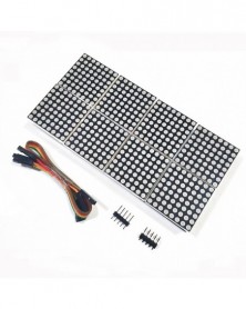
MAX7219 pontmátrix modul 8 pontmátrix 2*4 kijelző modul MCU vezérlő meghajtó modul
672 Ft 1 679 FtThe MAX7219 is an integrated serial input/output common-cathode display driver that connects a microprocessor to an 8-bit digital 7-segment LED display, or a bar graph display or 64 separate LEDs. It includes an on-chip B-type BCD encoder, multi-channel scan loop, segment word driver, and an 8*8 static RAM to store each data. Only one external register is used to set the segment current of each LED.
A convenient four-wire serial interface can be connected to all common microprocessors. Each data can be addressed without any need to overwrite all displays when updating. The MAX7219 also allows the user to choose whether to encode or not encode each data.
The entire device includes a 150A low-power shutdown mode, analog and digital brightness control, a scan limit register that allows the user to display 1-8 bits of data, and a detection mode that allows all LEDs to illuminate.
Only need 3 IO ports to drive 1 dot matrix! No flicker when the dot matrix is displayed! Support cascading!
Module parameters:
1. A single module can drive an 8*8 common cathode matrix
2. Module working voltage: 5V
3. Module size: length 13 cm X width 6.4 cm X height 1.3 cm
4. With 32 fixing screw holes, aperture 3mm
5. Module with input and output interface, support multiple module cascade
Wiring instructions:
1. The left side of the module is the input port, and the right side is the output port.
2. When controlling a single module, you only need to connect the input port to the CPU.
3. When multiple modules are cascaded, the input of the first module is connected to the CPU, the output is connected to the input of the second module, the output of the second module is connected to the input of the third module, and so on. ..
Take 51 MCU as an example:
VCC 5V
GND GND
DIN P2.2
CS P2.1
CLK P2.0
Shipping list:
1.MAX7219 dot matrix module four in one
2.20CM DuPont Line 5P
3. Pin header 2.54-5P -
-
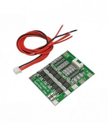
4S 30A 14,8V Li-ion Lithium 18650 Akkumulátor BMS Csomagok PCB védelmi kártya egyensúly integrált áramkörök
144 Ft 360 FtThis product is 4 series 3.7V lithium battery protection board.Large current protection board, continuous 30A current battery protection panel for the integrated circuit board that can be used for the protection of rechargeable (generally referred to as lithium batteries).The lithium battery (rechargeable) is required to be protected by its own characteristics.Materials due to the lithium battery itself determines that it can't be overcharge, discharge, over current, short circuit and ultra high temperature charge and discharge, so the lithium lithium battery components will always follow a belt sampling resistance protection board and a piece of current protecting device. -
-
10db ESP8266 soros WIFI modul adapterlap Az ESP-07, ESP-12F, ESP-12E vezeték nélküli kártya arduinohoz
105 Ft 263 FtDIY serial port WIFI ESP8266 module adapter board ESP-07 ESP-12 (module not included)
The resistance is not welded, you need to weld it yourself -
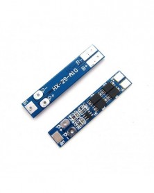
2S 7.4V 8A Li-ion 18650 lítium akkumulátortöltő védőkártya 8.4V túláram túltöltés/túlkisülés védelem
55 Ft 138 FtEigenschappen van de lithium batterij bescherming boord:
Model: HX-2 S-A10
Maat: 41*8*2.2mm
Maximale werkende stroom: 8 een
Maximale momentane stroom: 16 een
Statische stroom: minder dan 10uA
Weerstand: minder dan 300 m Ω
Laadspanning: 8.4 v-9 v
Overladen bereik: 4.25-4.35 v plus of min 0.05 v
Over voltage bereik: 2.5-3.0 v plus of min 0.05 v
Werktemperatuur:-40- 50 ℃
Opslag:-40- 80 ℃
Effectieve levensduur: meer dan 50,000 uur
Kortsluiting bescherming: te beschermen en herstellen moet lading
De bescherming boord grootte en apparaat beschrijving;
De beschermende plaat grootte is 41*8*2.2mm
Lassen punt beschrijving:
· B batterij anode;
· B-sluit batterij negatieve terminal;
· MMB sluit batterij 1 om batterij 2;
· P opladen/ontladen juiste polen (opladen einde/ontladen einde sharing);
· P-opladen/ontladen terminal negatieve terminal (opladen einde/ontladen einde sharing).
-
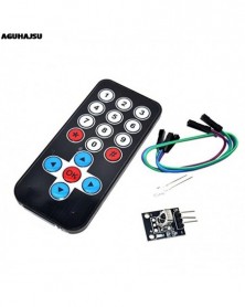
1 készlet infravörös infravörös vezeték nélküli távirányító modul készletek barkácskészlet HX1838 Arduino
76 Ft 191 Ft
Features:
Latest infrared wireless remote control kit consists Mini Slim 38KHz IR remote control and infrared receiver modules, Mini Slim infrared remote control with 17 function keys, firing distances of up to 8 meters, ideal for a variety of devices in the control room. IR receiver module can receive standard 38KHz modulation remote control signal, through programming, you can achieve remote control signal decoding operation, which can produce a variety of remote control robots and interactive works.
Ultra-thin infrared remote control product parameters:
1 Transmission Distance: 8m above (specific and surroundings, the receiver sensitivity and other factors)
2 Effective angle: 60 degrees
3 Sticking Material: 0.125mmPET, the effective life of 20,000 times.
4. Stable quality, cost-effective
5 quiescent current 3-5uA, dynamic current 3-5mA.
#include
int RECV_PIN = 11;
IRrecv irrecv(RECV_PIN);
decode_results results;
void setup()
{
Serial.begin(9600);
irrecv.enableIRIn(); // Start the receiver
}
void loop() {
if (irrecv.decode(&results)) {
Serial.println(results.value, HEX);
irrecv.resume(); // Receive the next value
}
} -
-
-
Alumínium héj CP2102 USB 2.0 - TTL UART modul 6 Pin soros átalakító STC Cserélje ki az FT232 modul támogatását 5v/3.3v
159 Ft 397 FtStable and reliable chipset CP2102
USB specification 2.0 compliant with full-speed 12Mbps.
Standard USB type A male and TTL 5pin connector. 5pins for 3.3V,TXD,RXD,GND & 5V
All handshaking and modem interface signals
Baud rates: 300 bps to 1.0Mbps.
Byte receive buffer; 640 byte transmit buffer.
Hardware or X-On/X-Off handshaking supported.
Event character support Line break transmission.
USB suspend states supported via SUSPEND pins.
Temperature Range: -40° to 85°.
Supports Windows 98SE, 2003, XP, Vista, Window7, Mac OSX , Linux 2.6.x and 2.4.36
Maximum baud rate 115200 perfect support! No longer distressed STC12 Series, STC11, STC15 series Burn! -
1x AAA-ért - 1x 2x 3x 4x Aaa Batterij Box Case Houder Met Draad Leads Side By Side Accubak Aansluiten Soldeer Voor 1-4 Stuks
44 Ft 110 FtThe battery holders with leads are connected in series:
One Section 3.7V
Two Section 7.4V
Three sections 11.1V
Four sections 14.8V -
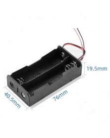
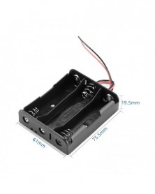
2x AAA-ért - 1x 2x 3x 4x Aaa Batterij Box Case Houder Met Draad Leads Side By Side Accubak Aansluiten Soldeer Voor 1-4 Stuks
52 Ft 131 FtThe battery holders with leads are connected in series:
One Section 3.7V
Two Section 7.4V
Three sections 11.1V
Four sections 14.8V -
3x AAA-hoz - 1x 2x 3x 4x Aaa Batterij Box Case Houder Met Draad Leads Side By Side Accubak Aansluiten Soldeer Voor 1-4 Stuks Aaa
58 Ft 145 FtThe battery holders with leads are connected in series:
One Section 3.7V
Two Section 7.4V
Three sections 11.1V
Four sections 14.8V -
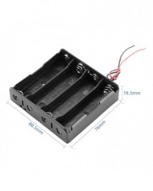
4x AAA-hoz - 1x 2x 3x 4x Aaa Batterij Box Case Houder Met Draad Leads Side By Side Accubak Aansluiten Soldeer Voor 1-4 Stuks Aaa
70 Ft 176 FtThe battery holders with leads are connected in series:
One Section 3.7V
Two Section 7.4V
Three sections 11.1V
Four sections 14.8V -
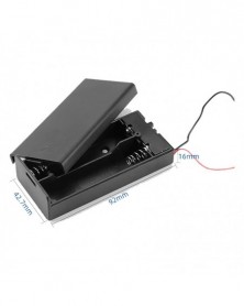
2x AAA-hoz Fedővel - 1x 2x 3x 4x Aaa Batterij Box Case Houder Met Draad Leads Side By Side Accubak Aansluiten Soldeer Voor 1-4
82 Ft 205 FtThe battery holders with leads are connected in series:
One Section 3.7V
Two Section 7.4V
Three sections 11.1V
Four sections 14.8V