Elektronikus alkatrészek és félvezetők
-
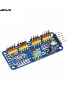
1db 16 csatornás 12 bites PWM/Servo Driver - I2C interfész - PCA9685 Raspberry Pi DIY szervopajzs modulhoz
242 Ft 605 FtDescription:
Want to make a hexapod walker? Maybe you're making a piece of art with tons of moving parts, or you need to drive a ton of LEDs with precise PWM output. Your microcontroller has a limited number of PWM outputs, and you find yourself running out! Not with the Adafruit 16-Channel 12-bit PWM/Servo Driver - I2C interface. With this pwm and servo driver breakout, you can control 16 free-running PWM outputs with just two pins! Need to run more than 16 PWM outputs? No problem. Chain together up to 62 of these beauties for up to an outstanding 992 PWM outputs.
Features:
Dimensions (no headers or terminal block) 2.5" x 1" x 0.1" (62.5mm x 25.4mm x 3mm)
Weight (no headers or terminal block): 5.5grams
Weight (with 3x4 headers & terminal block): 9grams
This board/chip uses I2C 7-bit address between 0x60-0x80, selectable with jumpers
Terminal block for power input (or you can use the 0.1" breakouts on the side)
Reverse polarity protection on the terminal block input
Green power-good LED
3 pin connectors in groups of 4 so you can plug in 16 servos at once (Servo plugs are slightly wider than 0.1" so you can only stack 4 next to each other on 0.1" header
"Chain-able" design
A spot to place a big capacitor on the V line (in case you need it)
220 ohm series resistors on all the output lines to protect them, and to make driving LEDs trivial
Solder jumpers for the 6 address select pins
i2c-controlled PWM driver with a built in clock. Unlike the TLC5940 family, you do not need to continuously send it signal tying up your microcontroller, its completely free running!
It is 5V compliant, which means you can control it from a 3.3V microcontroller and still safely drive up to 6V outputs (this is good for when you want to control white or blue LEDs with 3.4 forward voltages)
6 address select pins so you can wire up to 62 of these on a single i2c bus, a total of 992 outputs - that's a lot of servos or LEDs
Adjustable frequency PWM up to about 1.6 KHz
12-bit resolution for each output - for servos, that means about 4us resolution at 60Hz update rate
Configurable push-pull or open-drain output
Output enable pin to quickly disable all the outputs
(1)Drive board connected to Arduino:
The PWM driver board uses the I2C method, so only four lines can be connected to the Arduino device:
"Classic" Arduino pin mode:
5v -> VCC
GND -> GND
Analog 4 -> SDA
Analog 5 -> SCL
Old Mega pin way:
5v -> VCC
GND -> GND
Digital 20 -> SDA
Digital 21 -> SCL
R3 and later Arduino pin method (Uno, Mega &
Leonardo):
(These boards have dedicated SDA and SCL pins)
5v -> VCC
GND -> GND
SDA -> SDA
SCL -> SCL
VCC pin is only for the chip power supply, if you want to connect the servo or LED lights, use the V pin power supply, V pin supports 3.3 ~ 6V power supply (chip safe voltage 5V). It is recommended to connect the external power supply via the power supply terminal.
(2) power supply part:
Most of the servo design voltage is 5 ~ 6V, especially in a number of steering gear at the same time running, with the need for high-power power supply. If you are directly using the Arduino 5V pin to power the servo directly, there are some unpredictable problems, so we recommend that you have a suitable external power supply for the drive board.
(3) Connect the servo:
Most servos are connected using standard 3-wire female plugs, as long as the corresponding pin into the driver board on it. (Ground wire is generally black or brown, the signal line is generally yellow or white)
(4) for the driver board assigned address:
Each drive board of the cascade needs to have a unique access address. The initial I2C address of each driver board is 0 × 40, you can modify the upper right corner of the jumper I2C address. Connect a jumper with solder to indicate a binary number "1".
Board 0: Address = 0x40
Offset = binary 00000 (default)
Board 1: Address = 0x41 Offset = binary 00001 (as shown above, connected to A0)
Board 2: Address = 0x42 Offset = binary 00010 (connect to A1)
Board 3: Address = 0x43 Offset = binary 00011 (connect A0 and A1)
Board 4: Address = 0x44 Offset = binary 00100 (connect to A2)
And so on. . .
Code example:
#include
#include
Adafruit_PWMServoDriver pwm1 =
Adafruit_PWMServoDriver (0 × 40);
Adafruit_PWMServoDriver pwm2 =
Adafruit_PWMServoDriver (0x41);
Void setup () {
Serial.begin (9600);
Serial.println ( "16 channel
PWM test! ");
Pwm1.begin ();
Pwm1.setPWMFreq (1600); //
This is the maximum PWM frequency
Pwm2.begin ();
Pwm2.setPWMFreq (1600); //
This is the maximum PWM frequency -
-
SPI/IIC GY-9250 MPU 9250 MPU-9250 9 tengelyes hozzáállás giroszkóp gyorsító mágnesmérő érzékelő modul MPU9250
604 Ft 1 509 FtProduct Parameters
Module Model: GY-9250
Use Chip: MPU-9250
Power supply :3-5v (internal low dropout regulator)
Communication: Standard IIC/SPI communication protocol (Chip 16bit AD converter, the output data 16 )
Gyro range: ± 250 500 1000 2000 ° / s
Acceleration range: ± 2 ± 4 ± 8 ± 16g
Magnetic field range: ± 4800uT
Using Immersion Gold PCB, machine welding process to ensure quality
2.54mm pin pitch
Module size 15mm * 25mm -
-
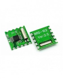
FM sztereó rádió RDA5807M vezeték nélküli modul RRD-102V2.0 Arduinohoz
60 Ft 150 FtDescription:
Product Overview
"RRD-102V2.0" stereo radio module (FM Stereo radio Module) high sensitivity, low power consumption, ultra- small size of the FM stereo radio module . Using RDA Microelectronics of RDA5807M ( or RDA5802NM), this circuit fewer external components , the noise factor is minimal. Small size, low power consumption , low cost, simple application , the use of a wide range of advantages. Is an easy -to-use and possessed highly cost-effective single -chip FM stereo radio module.
A: Move DVD, TV, MP3, MP4 and other built -in FM wide-band wireless receiver module.
B: mining, business , campus , residential, tourist areas and other public places, stereo FM radio system .
C: wireless audio and wireless stereo headset functionality.
D: GPS navigation, TV broadcasting systems and other wireless FM radio .
E: high-end game consoles and wireless audio electronic toys.
F: mobile phones , mobile phones, intercom systems, mobile radio devices and other stereo radio .
G: PDAS and Notebook PC and other peripheral applications .
Functional Characteristics
A, using a common 102BC module package , users can directly replace the use , without changing the circuit design.
B, high sensitivity, low noise, anti-interference ability , very few external components , small size (11 * 11.2MM Max), extremely simple to use .
C, 76-108MHz FM band worldwide compatible ( 76-91MHz , including Japan , America and Europe 87.5-108.5MHz).
D, I2C serial data communications bus interface , support for external reference clock input.
E, COMS technology fully integrated single-chip integrated circuits , power consumption is minimal.
F, built-in high-precision A / D ( analog ) and digital frequency synthesizer.
G, built-in LDO regulator , low power, wide voltage range (2.7-3.6VDC).
H, built-in noise reduction, soft mute, bass boost circuit design.
I, 32Ω load high power audio output, headphone connections are direct , no external audio driver amplifier .
J, the application is simple , low cost , cost-effective -
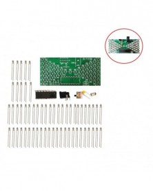
5V-os elektronikus homokóra barkácskészlet Vicces elektromos gyártási készletek precíz LED lámpákkal, kétrétegű PCB
124 Ft 310 FtThe suite adopts 1.6mm double layer PCB, and the circuit consists of 57 pieces warm white LED. Under the control of MCU program, it displays analog hourglass image. The micro switch can adjust the speed of hourglass, the bright LED quantity at the same time is 28, and it can be used as decoration of small night light. 0.5W power consumption. -
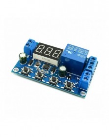
Akkumulátor töltő/kisütési modul integrált feszültségmérő alacsony feszültség/túlfeszültség védelem időzítés
200 Ft 501 FtBattery charge and discharge module integrated voltmeter undervoltage and overvoltage protection timing charge and discharge with communication function
Module Highlights:
1. Battery charge and discharge intelligent control;
2. You can set the charge and discharge time;
3. With serial communication function, real-time monitoring of the working status of the relay through the serial port;
4. Additional signal output, when the relay to meet the conditions, the output high, you can control other equipment.
5. A key emergency stop function (STOP button), with reverse protection, reverse does not burn.
Operating mode:
Voltage upper limit: UL1, voltage lower limit nL1, the voltage upper limit is greater than the voltage lower limit (UL1> nL1)
U-1: Charging measurement: When the measured voltage is lower than the lower limit voltage, the relay pulls above; the upper limit voltage, the relay is disconnected.
U-2: charge measurement time control: set the charging time (OP); when the measured voltage is lower than the lower limit voltage, the relay pull, and then start the countdown OP time, the end of the timer, the relay off; when the measured voltage is higher than the upper limit voltage , The relay is disconnected.
U-3: Discharge detection: When the measured voltage is lower than the lower limit voltage, the relay is off, above the upper limit voltage, the relay pulls;
U-4: discharge detection time control: set the discharge time (OP); when the measured voltage is higher than the upper limit voltage, the relay pull, and then start the countdown OP time, the end of the timer, the relay off; when the measured voltage below the lower limit voltage , The relay is disconnected;
U-5: voltage in the range, the relay pull: when the measured voltage between the upper and lower limits, the relay pull, the other circumstances open;
U-6: voltage outside the interval, the relay pull: the measured voltage below the lower limit voltage or higher than the upper limit voltage, the relay pull, the other case the relay is off.
Product parameters:
1: Power supply voltage: DC6--40V, voltage detection range DC 0--60V, suitable for less than 60V of the various batteries, voltage measurement error ± 0.1V.
2: charge and discharge time (OP) range: 0 - 999 minutes.
How do I set parameters?
1. First, according to their needs, to determine the requirements of the work model;
2. According to the working mode of the relay, in the main interface (when the module is powered on, it will flash the current mode of operation, the default U-1 mode, and then enter the main interface) press the SET button for 2 seconds and then release, enter the selection Mode interface, UP, DOWN button to select the mode to be set (U-1 ~ U-6);
3. After selecting the mode, assume that we have selected the U-1 mode and press the SET button to set the corresponding parameter. The parameter to be set will flash (UL1 voltage upper limit, nL1 voltage lower limit, OP conduction time), press UP, DOWN Key to increase or decrease, you can always press the key to quickly increase or decrease, press the SET button to set the current mode of the next parameter, the process above;
4. Set the parameters, and then press the SET button for 2 seconds to release, the current setting mode will flash, and then return to the main interface, set the parameters of success!
5. In the main interface, press the DOWN key to achieve voltage and time switching.
Mode selection interface: press the SET button for a long time to enter the mode selection interface, set the finished, a long time press the SET button and then release the exit mode selection interface, back to the main interface.
Additional features:
1. Data upload: through the serial port to achieve data upload, interval 1s upload a voltage and run time, easy to post-data analysis;
2. Serial port settings parameters: You can set the mode and parameters through the serial port, more convenient;
3. An extra signal output, when the relay to meet the conditions, the output high, the other output low.
Serial port control (TTL level communication)
Communication standard:
The baud rate is 115200 bps
Data bits: 8
Stop bit: 1
Check digit: none
Flow control: none
Serial command:
"U-1": Operating mode (range U-1 to U-6)
"000": 0 - does not enable timing function, non-0 - enable timing function (range 001 to 999)
"Dw02.9": Set the lower limit voltage
"Up10.1": set the upper limit voltage (range 00.0V ~ 99.9V)
"Get": Get the current settings
"On": Allows the relay to turn on
"Off": Always turn off the relay
"Start": start uploading data
"Stop": stop uploading data
The above command can be any combination of two, need to be separated by commas
Such as: "dw02.9, up10.1" set the lower limit voltage 02.9V upper limit voltage 10.1V
Upload Status: Test Voltage On Time Status
"00.0V, 00: 00: 00, OP \ r \ n"
00.0V: Measured voltage
00:00:00: Relay on time
Status: OP relay on, CL relay off
STOP key function expansion:
Relay enable mode:
1. ON: OP conduction time, the relay allows conduction;
2. OFF: The relay is disabled and is always off;
Press the STOP button on the main interface to switch between ON and OFF, the current status will flash, and then return to the main interface. (This function is an emergency stop function, a key to disconnect the relay)
Sleep mode:
1. C-P sleep mode: within five minutes, without any operation, the digital tube automatically shut down the display, the program normal operation;
2. O-d normal mode: digital tube is always open display;
Press and hold the STOP button for 2 seconds to release, to achieve C-P and O-d state of the switch, the current state will flash, and then return to the main interface. -
10 rozsdamentes acél tűkészlet PCB elektronikus áramkör átmenő furat tű kiforrasztó hegesztő javító szerszám 100 mm
51 Ft 128 FtProduct model:0.5/0.6/0.7/0.8/0.9/1/1.1/1.2/1.4/1.5
-
KIT2 - PICKIT2 KIT3 PIC KIT3.5 PICKIT 3 programozó offline programozás PIC mikrokontroller chip monopólium
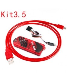
756 Ft 1 890 FtPICKIT3 main features:
1, the download speed is fast. The USB connection is stable than ICD2\KIT2.
2, offline programming function. Development and debugging programming can be used, and the product batch offline programming is also good.
3. Power supply output, internal voltage can be directly controlled by MPLAB IDE software.
4, PIKCIT3, support WIN7 system. ICD2\KIT2 does not support 64-bit WIN7
5, ultra small size: 95 * 39 * 11MM
6, full patch design, automatic patch processing, product quality is more stable and reliable.
PICKIT3 is used to connect to the target board:
PICSIT3's ICSP interface pin definition: -
KIT3 - PICKIT2 KIT3 PIC KIT3.5 PICKIT 3 programozó offline programozás PIC mikrokontroller chip monopólium
821 Ft 2 052 FtPICKIT3 main features:
1, the download speed is fast. The USB connection is stable than ICD2\KIT2.
2, offline programming function. Development and debugging programming can be used, and the product batch offline programming is also good.
3. Power supply output, internal voltage can be directly controlled by MPLAB IDE software.
4, PIKCIT3, support WIN7 system. ICD2\KIT2 does not support 64-bit WIN7
5, ultra small size: 95 * 39 * 11MM
6, full patch design, automatic patch processing, product quality is more stable and reliable.
PICKIT3 is used to connect to the target board:
PICSIT3's ICSP interface pin definition: -
KIT3.5 - PICKIT2 KIT3 PIC KIT3.5 PICKIT 3 programozó offline programozás PIC mikrokontroller chip monopólium
850 Ft 2 126 FtPICKIT3 main features:
1, the download speed is fast. The USB connection is stable than ICD2\KIT2.
2, offline programming function. Development and debugging programming can be used, and the product batch offline programming is also good.
3. Power supply output, internal voltage can be directly controlled by MPLAB IDE software.
4, PIKCIT3, support WIN7 system. ICD2\KIT2 does not support 64-bit WIN7
5, ultra small size: 95 * 39 * 11MM
6, full patch design, automatic patch processing, product quality is more stable and reliable.
PICKIT3 is used to connect to the target board:
PICSIT3's ICSP interface pin definition: -
-
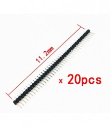
20 DB 40 tűs, 2,54 mm-es egysoros, egyenes dugaszfej csatlakozószalag PBC Ardunio molewei-hez
88 Ft 219 FtFeatures:
Pitch 2.54mm
Gender of Connector: Male
Number of Pins: 40Pin
Type of Row: Single-Row
Type of connector: Straight -
-
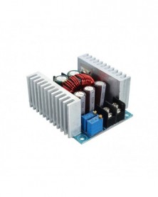
DC 300W 20A CC CV Állandó Áram Állítható Lelépés Átalakító Feszültség Buck Áramforrás modul
316 Ft 790 FtFeatures:
With a wide input voltage range from 6V to 40V, the step-down converter can accurately adjust output voltage and current.
The efficiency can be up to 96% , measured at 20A, converting 24V to 12V.
It is designed with 75V/80A large current dual MOS tube.
Input and output use high frequency low resistance electrolytic capacitor, low ripple, stable output.
Wiring is convenient with these large current 30A screw terminals.
The buck module has 2 heat sink that could enhance heat dissipation.
When there is a big difference between input and output voltage, please decrease power and current.
Specifications:
Input Voltage: 6V to 40V DC(10V to 40V is suggested)
Output Voltage: 1.2V to 36V DC
Output Current: 20A(max.), 15A(suggested)
Efficiency: 95% (24V to 12V, 20A)
Output Ripple: ≤50mV
Wiring Method: Terminal
Short Circuit Protection: Self-recovery(cannot short circuit for long time)
Size: 60 x 53 x 27mm / 2.36 x 2.08 x 1.06"
VO : Output positive
VO-: Output negative
IN: Input positive
-IN: Input negative
CV: Output voltage adjustment
CC: Output current adjustment
EN: Enable, low voltage level shut off output; suspension, high voltage level is effective
When input and output is common grounded, no-load CV output constant voltage,CC output constant current
Package Include:
1 x 300W 20A Constant Current Adjustable Buck Converter Step-Down Voltage Module -
-
-
220V elektromos forrasztópáka külső fűtött forrasztópáka kézi hegesztő forrasztószerszámkészlet 60W amerikai
168 Ft 419 FtNote:
1. Keep the welding nozzle head always covered with tin.
2. Do not use strong acid flux when soldering tin .
3. Do not use a rasp or hammer to setbacks and beat the tip.
4. In the presence of non-stick tin, polish the welding nozzle by fine sand skin, and then infiltrate it with flux, finally paint tin
5. When electric soldering iron is energized, it is strictly forbidden to disassemble its electric parts.
6. When the soldering iron is used for the first time, here comes out a smoke from end of the tip, which is normal and will naturally disappear in ten minutes.
7. When using electric soldering iron, a soldering station with a natural cooling structure should be equipped. -
-
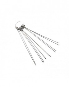
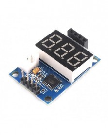
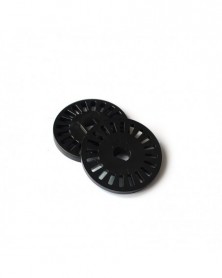
10 db kódolt lemezkódoló, 20 motor fordulatszám-érzékelő a robotsebesség-teszthez arduino-hoz
58 Ft 145 Ft10PCS Coded Disc Encoder 20 Holds Motor Speed Sensor for Robot Speed Test For arduino -
-
-