Tesztberendezés alkatrészei és tartozékai
-
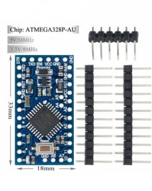
Szín: Type-C USB 3-15V - MICRO/MINI/TYPE-C USB ATMEGA32U4 Modul 5V 16MHz alaplap Arduino ATMEGA32U4-AU/MU vezérlőhöz Pro
1 070 Ft 1 946 FtDescription:
The Pro Micro is similar to the Pro Mini except with an ATmega32U4 on board.
The USB transceiver inside the 32U4 allows us to add
USB connectivity on-board and do away with bulky external USB interface.
This tiny little board does all work for Arduino tricks that you're familiar with:
4 channels of 10-bit ADC, 5 PWM pins, 12 DIOs as well as
hardware serial connections Rx and Tx. Running at 16MHz and 5V,
this board will remind you a lot of your other favorite for Arduino-compatible boards but this little guy can go just about anywhere.
There is a voltage regulator on board so it can accept voltage up to 6V(Blue board)/18V(Black board).
If you're supplying unregulated power to the board, be sure to connect to the "RAW" pin on not VCC.
This latest revision corrects the silk error from the last version of the board so that pin 14 is correctly labeled.
We've also added a PTC fuse and diode protection to the power circuit and corrected the RX and TX LED circuit.
Features:
ATMega 32U4 running at 5V/16MHz
Supported under for Arduino IDE v1.0.1
On-Board MINI USB connector for programming
4 x 10-bit ADC pins
12 x Digital I/Os (5 are PWM capable)
Rx and Tx Hardware Serial Connections
Our Smallest for Arduino-Compatible Board Yet! -
Szín: TYPE-C USB 3-6V - MICRO/MINI/TYPE-C USB ATMEGA32U4 Modul 5V 16MHz alaplap Arduino ATMEGA32U4-AU/MU vezérlőhöz Pro
1 084 Ft 1 971 FtDescription:
The Pro Micro is similar to the Pro Mini except with an ATmega32U4 on board.
The USB transceiver inside the 32U4 allows us to add
USB connectivity on-board and do away with bulky external USB interface.
This tiny little board does all work for Arduino tricks that you're familiar with:
4 channels of 10-bit ADC, 5 PWM pins, 12 DIOs as well as
hardware serial connections Rx and Tx. Running at 16MHz and 5V,
this board will remind you a lot of your other favorite for Arduino-compatible boards but this little guy can go just about anywhere.
There is a voltage regulator on board so it can accept voltage up to 6V(Blue board)/18V(Black board).
If you're supplying unregulated power to the board, be sure to connect to the "RAW" pin on not VCC.
This latest revision corrects the silk error from the last version of the board so that pin 14 is correctly labeled.
We've also added a PTC fuse and diode protection to the power circuit and corrected the RX and TX LED circuit.
Features:
ATMega 32U4 running at 5V/16MHz
Supported under for Arduino IDE v1.0.1
On-Board MINI USB connector for programming
4 x 10-bit ADC pins
12 x Digital I/Os (5 are PWM capable)
Rx and Tx Hardware Serial Connections
Our Smallest for Arduino-Compatible Board Yet! -
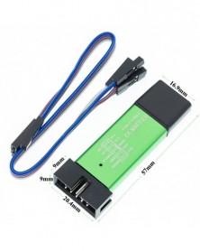
ATTINY88 Micro Development Board 16Mhz/Digispark ATTINY85 Upgraded/NANO V3.0 ATmega328 Extended Arduino kompatibilis
202 Ft 367 FtBBS: http://forum.mhetlive.com/topic/47/mh-et-live-tiny8-16-0mhz
The MH-ET LIVE Tiny88(16.0Mhz) based microcontroller development board similar to the Arduino line, only cheaper, smaller, and a bit less powerful. With the ability to use the familiar Arduino IDE the MH-ET LIVE Tiny88(16.0Mhz) is a great board to jump into electronics, or perfect for when an other board is too big or too much.The MH-ET LIVE Tiny88(16.0Mhz) is shipped fully assembled except for the headersincluded and easy to solder them by yourself.
Specs:
Support for the Arduino IDE 1.0 (OSX/Win/Linux)
1. Power via USB or External Source - 5v or 7-35v (12v or less recommended,
automatic selection)
2. On-board 500ma 5V Regulator
3. Built-in USB
4. 26 I/O Pins (2 are used for USB only if your program actively communicates over USB, otherwise you can use all 6 even if you are programming via USB)
5. 8k Flash Memory (about 6k after bootloader)
6. I2C and SPI
7. 26-PWM (26 pins with Software PWM,only two(D9,D10) with hardware PWM )
8. ADC on 8 pins
9. Power LED and Test/Status LED
10. Size(mm):44.5x18.3x3 -
Szín: BME280-3,3V - BME280 3,3 V 5 V digitális érzékelő Hőmérséklet Páratartalom Barometrikus nyomás érzékelő modul
564 Ft 1 026 Ft
Description
ME-BME280 is a Breakout Board featuring a Bosch Sensortec ME280 Temperature, Humidity & Pressure Sensor.
The board has selectable I2C address jumper (solder link GS2), I2C pull-up resistors, 7 pin header 2.54mm, and two mounting holes 3.5mm.
Default setting of the board; single power rail Vdd=Vdd_IO (solder link GS1), pull-ups resistors (R2, R3) 10k, protocol selector resistor 0ohm (R1), decoupling capacitors 0.1uF on both power supply pins Vdd & Vdd_IO.
If you connect board to both power rails VDD_IO 1.8V and VDD 3.3V be sure to remove the power rail jumper GS1!
BME280 Features
- Package 2.5 mm x 2.5 mm x 0.93 mm metal lid LGA
- Digital interface I2C (up to 3.4 MHz) and SPI (3 and 4 wire, up to 10 MHz)
- Supply voltage VDD main supply voltage range: 1.71 V to 3.6 V
VDDIO interface voltage range: 1.2 V to 3.6 V
- Current consumption 1.8 uA @ 1 Hz humidity and temperature
2.8 uA @ 1 Hz pressure and temperature
3.6 uA @ 1 Hz humidity, pressure and temperature
0.1 uA in sleep mode
- Operating range -40… 85 C, 0…100 % rel. humidity, 300…1100 hPa- Humidity sensor and pressure sensor can be independently enabled/disabled
Bosch has stepped up their game with their new BMP280 sensor, an environmental sensor with temperature, barometric pressure that is the next generation upgrade to the BMP085/BMP180/BMP183. This sensor is great for all sorts of weather sensing and can even be used in both I2C and SPI!
This precision sensor from Bosch is the best low-cost, precision sensing solution for measuring barometric pressure with ±1 hPa absolute accuraccy, and temperature with ±1.0°C accuracy. Because pressure changes with altitude, and the pressure measurements are so good, you can also use it as an altimeter with ±1 meter accuracy
The BME280 is the next-generation of sensors from Bosch, and is the upgrade to the BMP085/BMP180/BMP183 - with a low altitude noise of 0.25m and the same fast conversion time. It has the same specifications, but can use either I2C or SPI. For simple easy wiring, go with I2C. If you want to connect a bunch of sensors without worrying about I2C address collisions, go with SPI.
-
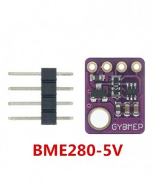
Szín: BME280-5V - BME280 3.3V 5V digitális érzékelő hőmérséklet páratartalom légköri nyomás érzékelő modul I2C
564 Ft 1 026 Ft
Description
ME-BME280 is a Breakout Board featuring a Bosch Sensortec ME280 Temperature, Humidity & Pressure Sensor.
The board has selectable I2C address jumper (solder link GS2), I2C pull-up resistors, 7 pin header 2.54mm, and two mounting holes 3.5mm.
Default setting of the board; single power rail Vdd=Vdd_IO (solder link GS1), pull-ups resistors (R2, R3) 10k, protocol selector resistor 0ohm (R1), decoupling capacitors 0.1uF on both power supply pins Vdd & Vdd_IO.
If you connect board to both power rails VDD_IO 1.8V and VDD 3.3V be sure to remove the power rail jumper GS1!
BME280 Features
- Package 2.5 mm x 2.5 mm x 0.93 mm metal lid LGA
- Digital interface I2C (up to 3.4 MHz) and SPI (3 and 4 wire, up to 10 MHz)
- Supply voltage VDD main supply voltage range: 1.71 V to 3.6 V
VDDIO interface voltage range: 1.2 V to 3.6 V
- Current consumption 1.8 uA @ 1 Hz humidity and temperature
2.8 uA @ 1 Hz pressure and temperature
3.6 uA @ 1 Hz humidity, pressure and temperature
0.1 uA in sleep mode
- Operating range -40… 85 C, 0…100 % rel. humidity, 300…1100 hPa- Humidity sensor and pressure sensor can be independently enabled/disabled
Bosch has stepped up their game with their new BMP280 sensor, an environmental sensor with temperature, barometric pressure that is the next generation upgrade to the BMP085/BMP180/BMP183. This sensor is great for all sorts of weather sensing and can even be used in both I2C and SPI!
This precision sensor from Bosch is the best low-cost, precision sensing solution for measuring barometric pressure with ±1 hPa absolute accuraccy, and temperature with ±1.0°C accuracy. Because pressure changes with altitude, and the pressure measurements are so good, you can also use it as an altimeter with ±1 meter accuracy
The BME280 is the next-generation of sensors from Bosch, and is the upgrade to the BMP085/BMP180/BMP183 - with a low altitude noise of 0.25m and the same fast conversion time. It has the same specifications, but can use either I2C or SPI. For simple easy wiring, go with I2C. If you want to connect a bunch of sensors without worrying about I2C address collisions, go with SPI.
-
Szín: RP2040 - Raspberry Pi Pico Board RP2040 kétmagos 264KB ARM kis fogyasztású mikroszámítógépek, nagy
432 Ft 785 FtThe Raspberry Pi Pico is a microcontroller board based on the Raspberry Pi RP2040 microcontroller chip. It has been designed to be a low-cost, high-performance microcontroller board with flexible digital interfaces. The Raspberry Pi Pico features two ARM Cortex-M0 cores run up to 133MHz; 256KB RAM; 30 GPIO pins; and a broad range of interfacing options. This is paired with 2MB of onboard QSPI Flash memory for code and data storage.
In addition to powerful hardware resources, Pico has rich and complete software support and community resources. It comes with a complete Rasberry Pi official C/C SDK, Micropython SDK. Just click "https://pico.raspberrypi.org/getting-started" to get started with Raspberry Pi Pico.
Pico has been designed to use either soldered 0.1" pin-headers (it is one 0.1" pitch wider than a standard 40-pin DIP package) or can be used as a surface-mountable 'module', as the user IO pins are also castellated. There are SMT pads underneath the USB connector and BOOTSEL button, which allow these signals to be accessed if used as a reflow soldered SMT module.
Specification:
• RP2040 microcontroller chip designed by Raspberry Pi in the United Kingdom
• Dual-core Arm Cortex M0 processor, flexible clock running up to 133 MHz
• 264KB of SRAM, and 2MB of on-board Flash memory
• Castellated module allows soldering direct to carrier boards
• USB 1.1 with device and host support
• Low-power sleep and dormant modes
• Drag-and-drop programming using mass storage over USB
• 26 × multi-function GPIO pins
• 2 × SPI, 2 × I2C, 2 × UART, 3 × 12-bit ADC, 16 × controllable PWM channels
• Accurate clock and timer on-chip
• Temperature sensor
• Accelerated floating-point libraries on-chip
• 8 × Programmable I/O (PIO) state machines for custom peripheral support -
10 DB/LOT ESP8266 soros WIFI modell ESP8266-07 ESP-07 ESP07 Eredetiség garantált WIFI modul I74
1 569 Ft 2 852 FtFirmware can be achieved:
Convenient development environment, free virtual machine and familiar with the Linux system, directly in the Windows environment to develop, save development time, ahead of the market to seize;
Add AT CLDSTART, start the cloud connection, the default parameters for the security can Ai-Cloud cloud platform, the implementation of this directive, the system will automatically maintain the cloud connection and heartbeat package, and disconnected. The system handles all protocol layers.
AT CLDSTOPStop the cloud connection. Release all cloud-related system resources.
AT CLDSEND =Send data to the cloud.
Parameter is the data length, the implementation of this command, the system will return ">", then you can send a certain length of data.
Data reception
The following are the same as the "When the cloud data comes, you will receive CLD,
Len is the data length, data is the specific data.
Smart connection
AT CWMODE = 1
AT SMARTSTART = 1
This is done using ESP_TOUCH technology.
(1.2.0 version can be directly after the command "AT CWSTARTSMART", do not need to set the parameters, SmartConfig type can be automatically obtained, no need to set.
Added to join the cloud family group instructionsAT LANSTART, Can be easily joined the cloud family group, andAPPEnd connection to control;
Added exit to cloud family group instructionsAT CLDUNBIND, Module cloud control transfer? A command to exit the cloud family group, no longer bound by binding;
AddedWPSFeatures,AT CWWPSSTARTDirectly openWPS, More convenient configurationWiFiconnection;
AddedATinstructionAT CIOWRITECan be setIOState, an instruction can be controlled differentlyIOThe high and low levels;
AddedATinstructionAT CIOREADCan be readIOState, an instruction can be read differentlyIOstatus;
AddedATinstructionAT CSYSHEAPYou can view the rest at any timeRAMSize, the remaining space to grasp;
AddedATinstructionAT CIOADCCan be readADC, The input voltage range is0 ~ 1V; -
Szín: 315 MHz - 10 db 433 MHz-es RF adó és vevő modul összekötő készlet ARM/MCU WL 315MHZ/433MHZ vezeték nélküli
927 Ft 1 686 FtReceiver module parameters
1.Product Model: 433/315MHZ
2.Operating voltage: DC5V
3.Quiescent Current: 4MA
4.Receiving frequency: 433.92MHZ /315Mhz (optional)
5.Receiver sensitivity:-105DB
6.Size: 30 * 14 * 7mm
7.External antenna: 32CM single core wire, wound into a spiral Technical parameters of the transmitter head
1.Product Model: MX-FS-03V
2.Launch distance :20-200 meters (different voltage, different results)
3.Operating voltage :3.5-12V
4.Dimensions: 19 * 19mm
5.Operating mode: AM
6.Transfer rate: 4KB / S
7.Transmitting power: 10mW
8.Transmitting frequency: 433Mhz /315Mhz (optional)
9.An external antenna: 25cm ordinary multi-core or single-core line
10.Pinout from left → right: (DATA; VCC; GND) Application environment Remote control switch, receiver module, motorcycles, automobile anti-theft products, home security products, electric doors, shutter doors, windows, remote control socket, remote control LED, remote audio remote control electric doors, garage door remote control, remote control retractable doors, remote volume gate, pan doors, remote control door opener, door closing device control system, remote control curtains, alarm host, alarm, remote control motorcycle remote control electric cars, remote control MP3. Remark
1.VCC voltage module operating voltage and good power filtering;
2.Great influence on the antenna module reception, preferably connected to the 1/4 wavelength of the antenna, typically 50 ohm single conductor, the length of the antenna 433M of about 17cm;
3.Antenna position has also affected the reception of the module, the installation, the antenna as possible straight away from the shield, high pressure, and interference source; frequency used to receive, decode and oscillation resistor should match with the transmitter. -
Szín: 433 MHz - 10 db 433 MHz-es RF adó és vevő modul összekötő készlet ARM/MCU WL 315MHZ/433MHZ vezeték nélküli
903 Ft 1 641 FtReceiver module parameters
1.Product Model: 433/315MHZ
2.Operating voltage: DC5V
3.Quiescent Current: 4MA
4.Receiving frequency: 433.92MHZ /315Mhz (optional)
5.Receiver sensitivity:-105DB
6.Size: 30 * 14 * 7mm
7.External antenna: 32CM single core wire, wound into a spiral Technical parameters of the transmitter head
1.Product Model: MX-FS-03V
2.Launch distance :20-200 meters (different voltage, different results)
3.Operating voltage :3.5-12V
4.Dimensions: 19 * 19mm
5.Operating mode: AM
6.Transfer rate: 4KB / S
7.Transmitting power: 10mW
8.Transmitting frequency: 433Mhz /315Mhz (optional)
9.An external antenna: 25cm ordinary multi-core or single-core line
10.Pinout from left → right: (DATA; VCC; GND) Application environment Remote control switch, receiver module, motorcycles, automobile anti-theft products, home security products, electric doors, shutter doors, windows, remote control socket, remote control LED, remote audio remote control electric doors, garage door remote control, remote control retractable doors, remote volume gate, pan doors, remote control door opener, door closing device control system, remote control curtains, alarm host, alarm, remote control motorcycle remote control electric cars, remote control MP3. Remark
1.VCC voltage module operating voltage and good power filtering;
2.Great influence on the antenna module reception, preferably connected to the 1/4 wavelength of the antenna, typically 50 ohm single conductor, the length of the antenna 433M of about 17cm;
3.Antenna position has also affected the reception of the module, the installation, the antenna as possible straight away from the shield, high pressure, and interference source; frequency used to receive, decode and oscillation resistor should match with the transmitter. -
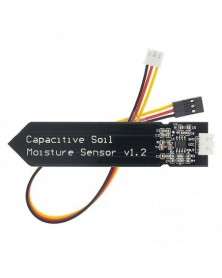
10 DB kapacitív talajnedvesség-érzékelő Korrózióálló, széles feszültségű vezeték Analóg kapacitív
988 Ft 1 797 FtThis analog capacitive soil moisture sensor measures soil moisture levels by capacitive sensing, rather than resistive sensing like other types of moisture sensor
It is made of a corrosion resistant material giving it a long service life
Insert it into soil and impress your friends with the real-time soil moisture data
This module includes an on-board voltage regulator which gives it an operating voltage range of 3.3 ~ 5.5V
This sensor is compatible with DFRobot 3-pin "Gravity" interface, which can be directly connected to the Gravity I/O expansion shield
Features:
Supports 3-Pin Gravity Sensor interface
Analog output
Applications:
Garden plants
Moisture detection
Intelligent agriculture
Specifications:
Operating Voltage: DC 3.3-5.5V
Output Voltage: DC 0-3.0V
Interface: PH2.0-3P
Size: 99x16mm/3.9x0.63"
Quantity: 10 Set
Note:
Please allow 1-3mm error due to manual measurement.pls make sure you do not mind before you bid
Due to the difference between different monitors, the picture may not reflect the actual color of the item. Thank you!
No Retail Package
Package Includes:
10 x Capacitive Soil Moisture Sensor
10 x Analog Sensor Cable -
10 db 1,3 hüvelykes TFT LCD képernyős kijelző modul 240240 IPS színes 7 tűs SPI interfész ST7789 IC illesztőprogram
3 121 Ft 5 675 FtDescription:
The TFT display provides a semiconductor switch for each pixel and each pixel is directly controlled by pulse. Therefore, each node is relatively independent and can be continuously controlled, which not only improves the response speed of the display, but also can be accurately controlled. The color level is displayed to make the TFT LCD color more realistic, the brightness is good, the contrast is high, the layering is strong and the color is bright.
Specification:
Viewing direction: IPS
LCD Size: 1.3 inch
Resolution: 240*240 ( There are two display way: horizontal display and vertical display, you can adjust the display direction. )
Interface: SPI Interface, 7PIN
Color: TFT Full Color
IC Driver: ST7789
Working temperature: -20-70℃
Working Voltage: 3.3V
Display area Size: 23.4*23.4mm
TFT Module Size: 27.78* 39.22mm
Pin:
GND: power supply
VCC: DC 3.3-5V
SCL: SPI Clock Cable
SDA:SPI Data Cable
RES: Reset
DC: SPI Choice/ Command Choice
BLK:Backlight control, default floating, low level off
Package Included:
1 * 1.3 inch TFT LCD Display Module -
Szín: A4988 Piros - 3D nyomtató alkatrészek A4988 DRV8825 léptetőmotor-meghajtó hűtőbordával SKR V1.3 1.4 GTR V1.0
124 Ft 226 FtAbout Drv8825
Introduction:
The DRV8825 stepper motor driver carrier is a breakout board for TI’s DRV8825 microstepping bipolar stepper motor driver.
The module has a pinout and interface that are nearly identical to those of our A4988 stepper motor driver carriers, so it can be used as a higher-performance drop-in replacement for those boards in many applications.
The DRV8825 features adjustable current limiting, overcurrent and overtemperature protection, and six microstep resolutions (down to 1/32-step). It operates from 8.2 – 45 V and can deliver up to approximately 1.5 A per phase without a heat sink or forced air flow (rated for up to 2.2 A per coil with sufficient additional cooling).
Features:
Simple step and direction control interface
Six different step resolutions: full-step, half-step, 1/4-step, 1/8-step, 1/16-step, and 1/32-step
Can interface directly with 3.3 V and 5 V systems
Over-temperature thermal shutdown, over-current shutdown, and under-voltage lockout
Short-to-ground and shorted-load protection
4-layer, 2 oz copper PCB for improved heat dissipation
Exposed solderable ground pad below the driver IC on the bottom of the PCB
Module size, pinout, and interface match those of our A4988 stepper motor driver carriers in most respects (see the bottom of this page for more information)
Adjustable current control lets you set the maximum current output with a potentiometer, which lets you use voltages above your stepper motor’s rated voltage to achieve higher step rates
Intelligent chopping control that automatically selects the correct current decay mode (fast decay or slow decay)
45 V maximum supply voltage
Built-in regulator (no external logic voltage supply needed)
Subdivision:
About A4988
Introduction:
This product is a breakout board for Allegro’s A4988 DMOS Microstepping Driver with Translator and Overcurrent Protection; please read the A4988 datasheet carefully before using this product. This stepper motor driver lets you to operate bipolar stepper motors in full-, half-, quarter-, eighth-, and sixteenth-step modes, with an output drive capacity of up to 35 V and 2 A.
The translator is the key to the easy implementation of the A4988. Simply inputting one pulse on the STEP input drives the motor one microstep. There are no phase sequence tables, high frequency control lines, or complex interfaces to program.The A4988 interface is an ideal fit for applications where a complex microprocessor is unavailable or is overburdened.
Feature:
Simple step and direction control interface;
Five different step resolutions: full-step, half-step, quarter-step, eighth-step, and sixteenth-step;
Adjustable current control lets you set the maximum current output with a potentiometer, which lets you use voltages above your stepper motor’s rated;
Voltage to achieve higher step rates;
3.3 and 5 V compatible logic supply
Intelligent chopping control that automatically selects the correct current decay mode (fast decay or slow decay);
Over-temperature thermal shutdown, under-voltage lockout, and crossover-current protection;
Short-to-ground and shorted-load protection.
Subdivision: -
Szín: A4988 zöld - 3D nyomtató alkatrészek A4988 DRV8825 léptetőmotor-meghajtó hűtőbordával SKR V1.3 1.4 GTR V1.0
124 Ft 226 FtAbout Drv8825
Introduction:
The DRV8825 stepper motor driver carrier is a breakout board for TI’s DRV8825 microstepping bipolar stepper motor driver.
The module has a pinout and interface that are nearly identical to those of our A4988 stepper motor driver carriers, so it can be used as a higher-performance drop-in replacement for those boards in many applications.
The DRV8825 features adjustable current limiting, overcurrent and overtemperature protection, and six microstep resolutions (down to 1/32-step). It operates from 8.2 – 45 V and can deliver up to approximately 1.5 A per phase without a heat sink or forced air flow (rated for up to 2.2 A per coil with sufficient additional cooling).
Features:
Simple step and direction control interface
Six different step resolutions: full-step, half-step, 1/4-step, 1/8-step, 1/16-step, and 1/32-step
Can interface directly with 3.3 V and 5 V systems
Over-temperature thermal shutdown, over-current shutdown, and under-voltage lockout
Short-to-ground and shorted-load protection
4-layer, 2 oz copper PCB for improved heat dissipation
Exposed solderable ground pad below the driver IC on the bottom of the PCB
Module size, pinout, and interface match those of our A4988 stepper motor driver carriers in most respects (see the bottom of this page for more information)
Adjustable current control lets you set the maximum current output with a potentiometer, which lets you use voltages above your stepper motor’s rated voltage to achieve higher step rates
Intelligent chopping control that automatically selects the correct current decay mode (fast decay or slow decay)
45 V maximum supply voltage
Built-in regulator (no external logic voltage supply needed)
Subdivision:
About A4988
Introduction:
This product is a breakout board for Allegro’s A4988 DMOS Microstepping Driver with Translator and Overcurrent Protection; please read the A4988 datasheet carefully before using this product. This stepper motor driver lets you to operate bipolar stepper motors in full-, half-, quarter-, eighth-, and sixteenth-step modes, with an output drive capacity of up to 35 V and 2 A.
The translator is the key to the easy implementation of the A4988. Simply inputting one pulse on the STEP input drives the motor one microstep. There are no phase sequence tables, high frequency control lines, or complex interfaces to program.The A4988 interface is an ideal fit for applications where a complex microprocessor is unavailable or is overburdened.
Feature:
Simple step and direction control interface;
Five different step resolutions: full-step, half-step, quarter-step, eighth-step, and sixteenth-step;
Adjustable current control lets you set the maximum current output with a potentiometer, which lets you use voltages above your stepper motor’s rated;
Voltage to achieve higher step rates;
3.3 and 5 V compatible logic supply
Intelligent chopping control that automatically selects the correct current decay mode (fast decay or slow decay);
Over-temperature thermal shutdown, under-voltage lockout, and crossover-current protection;
Short-to-ground and shorted-load protection.
Subdivision: -
Szín: DRV8825 - 3D nyomtató alkatrészek A4988 DRV8825 léptetőmotor-meghajtó hűtőbordával SKR V1.3 1.4 GTR V1.0 RAMPS
279 Ft 507 FtAbout Drv8825
Introduction:
The DRV8825 stepper motor driver carrier is a breakout board for TI’s DRV8825 microstepping bipolar stepper motor driver.
The module has a pinout and interface that are nearly identical to those of our A4988 stepper motor driver carriers, so it can be used as a higher-performance drop-in replacement for those boards in many applications.
The DRV8825 features adjustable current limiting, overcurrent and overtemperature protection, and six microstep resolutions (down to 1/32-step). It operates from 8.2 – 45 V and can deliver up to approximately 1.5 A per phase without a heat sink or forced air flow (rated for up to 2.2 A per coil with sufficient additional cooling).
Features:
Simple step and direction control interface
Six different step resolutions: full-step, half-step, 1/4-step, 1/8-step, 1/16-step, and 1/32-step
Can interface directly with 3.3 V and 5 V systems
Over-temperature thermal shutdown, over-current shutdown, and under-voltage lockout
Short-to-ground and shorted-load protection
4-layer, 2 oz copper PCB for improved heat dissipation
Exposed solderable ground pad below the driver IC on the bottom of the PCB
Module size, pinout, and interface match those of our A4988 stepper motor driver carriers in most respects (see the bottom of this page for more information)
Adjustable current control lets you set the maximum current output with a potentiometer, which lets you use voltages above your stepper motor’s rated voltage to achieve higher step rates
Intelligent chopping control that automatically selects the correct current decay mode (fast decay or slow decay)
45 V maximum supply voltage
Built-in regulator (no external logic voltage supply needed)
Subdivision:
About A4988
Introduction:
This product is a breakout board for Allegro’s A4988 DMOS Microstepping Driver with Translator and Overcurrent Protection; please read the A4988 datasheet carefully before using this product. This stepper motor driver lets you to operate bipolar stepper motors in full-, half-, quarter-, eighth-, and sixteenth-step modes, with an output drive capacity of up to 35 V and 2 A.
The translator is the key to the easy implementation of the A4988. Simply inputting one pulse on the STEP input drives the motor one microstep. There are no phase sequence tables, high frequency control lines, or complex interfaces to program.The A4988 interface is an ideal fit for applications where a complex microprocessor is unavailable or is overburdened.
Feature:
Simple step and direction control interface;
Five different step resolutions: full-step, half-step, quarter-step, eighth-step, and sixteenth-step;
Adjustable current control lets you set the maximum current output with a potentiometer, which lets you use voltages above your stepper motor’s rated;
Voltage to achieve higher step rates;
3.3 and 5 V compatible logic supply
Intelligent chopping control that automatically selects the correct current decay mode (fast decay or slow decay);
Over-temperature thermal shutdown, under-voltage lockout, and crossover-current protection;
Short-to-ground and shorted-load protection.
Subdivision: -
1 db GY-BME280-3.3 precíziós magasságmérő légköri nyomásérzékelő BME280 érzékelő modul 3.3V
613 Ft 1 115 Ft
Description
ME-BME280 is a Breakout Board featuring a Bosch Sensortec ME280 Temperature, Humidity & Pressure Sensor.
The board has selectable I2C address jumper (solder link GS2), I2C pull-up resistors, 7 pin header 2.54mm, and two mounting holes 3.5mm.
Default setting of the board; single power rail Vdd=Vdd_IO (solder link GS1), pull-ups resistors (R2, R3) 10k, protocol selector resistor 0ohm (R1), decoupling capacitors 0.1uF on both power supply pins Vdd & Vdd_IO.
If you connect board to both power rails VDD_IO 1.8V and VDD 3.3V be sure to remove the power rail jumper GS1!
BME280 Features
- Package 2.5 mm x 2.5 mm x 0.93 mm metal lid LGA
- Digital interface I2C (up to 3.4 MHz) and SPI (3 and 4 wire, up to 10 MHz)
- Supply voltage VDD main supply voltage range: 1.71 V to 3.6 V
VDDIO interface voltage range: 1.2 V to 3.6 V
- Current consumption 1.8 uA @ 1 Hz humidity and temperature
2.8 uA @ 1 Hz pressure and temperature
3.6 uA @ 1 Hz humidity, pressure and temperature
0.1 uA in sleep mode
- Operating range -40… 85 C, 0…100 % rel. humidity, 300…1100 hPa- Humidity sensor and pressure sensor can be independently enabled/disabled
Bosch has stepped up their game with their new BMP280 sensor, an environmental sensor with temperature, barometric pressure that is the next generation upgrade to the BMP085/BMP180/BMP183. This sensor is great for all sorts of weather sensing and can even be used in both I2C and SPI!
This precision sensor from Bosch is the best low-cost, precision sensing solution for measuring barometric pressure with ±1 hPa absolute accuraccy, and temperature with ±1.0°C accuracy. Because pressure changes with altitude, and the pressure measurements are so good, you can also use it as an altimeter with ±1 meter accuracy
The BME280 is the next-generation of sensors from Bosch, and is the upgrade to the BMP085/BMP180/BMP183 - with a low altitude noise of 0.25m and the same fast conversion time. It has the same specifications, but can use either I2C or SPI. For simple easy wiring, go with I2C. If you want to connect a bunch of sensors without worrying about I2C address collisions, go with SPI.
-
Szín: BME280-5V - BME280 5V 3,3V digitális érzékelő hőmérséklet páratartalom légköri nyomás érzékelő modul I2C
613 Ft 1 115 FtDescription
ME-BME280 is a Breakout Board featuring a Bosch Sensortec ME280 Temperature, Humidity & Pressure Sensor.
The board has selectable I2C address jumper (solder link GS2), I2C pull-up resistors, 7 pin header 2.54mm, and two mounting holes 3.5mm.
Default setting of the board; single power rail Vdd=Vdd_IO (solder link GS1), pull-ups resistors (R2, R3) 10k, protocol selector resistor 0ohm (R1), decoupling capacitors 0.1uF on both power supply pins Vdd & Vdd_IO.
If you connect board to both power rails VDD_IO 1.8V and VDD 3.3V be sure to remove the power rail jumper GS1!
BME280 Features
- Package 2.5 mm x 2.5 mm x 0.93 mm metal lid LGA
- Digital interface I2C (up to 3.4 MHz) and SPI (3 and 4 wire, up to 10 MHz)
- Supply voltage VDD main supply voltage range: 1.71 V to 3.6 V
VDDIO interface voltage range: 1.2 V to 3.6 V
- Current consumption 1.8 uA @ 1 Hz humidity and temperature
2.8 uA @ 1 Hz pressure and temperature
3.6 uA @ 1 Hz humidity, pressure and temperature
0.1 uA in sleep mode
- Operating range -40… 85 C, 0…100 % rel. humidity, 300…1100 hPa- Humidity sensor and pressure sensor can be independently enabled/disabled
Bosch has stepped up their game with their new BMP280 sensor, an environmental sensor with temperature, barometric pressure that is the next generation upgrade to the BMP085/BMP180/BMP183. This sensor is great for all sorts of weather sensing and can even be used in both I2C and SPI!
This precision sensor from Bosch is the best low-cost, precision sensing solution for measuring barometric pressure with ±1 hPa absolute accuraccy, and temperature with ±1.0°C accuracy. Because pressure changes with altitude, and the pressure measurements are so good, you can also use it as an altimeter with ±1 meter accuracy
The BME280 is the next-generation of sensors from Bosch, and is the upgrade to the BMP085/BMP180/BMP183 - with a low altitude noise of 0.25m and the same fast conversion time. It has the same specifications, but can use either I2C or SPI. For simple easy wiring, go with I2C. If you want to connect a bunch of sensors without worrying about I2C address collisions, go with SPI.
-
Szín: BME280-3,3V - BME280 5V 3,3V digitális érzékelő hőmérséklet páratartalom légköri nyomás érzékelő modul I2C
613 Ft 1 115 FtDescription
ME-BME280 is a Breakout Board featuring a Bosch Sensortec ME280 Temperature, Humidity & Pressure Sensor.
The board has selectable I2C address jumper (solder link GS2), I2C pull-up resistors, 7 pin header 2.54mm, and two mounting holes 3.5mm.
Default setting of the board; single power rail Vdd=Vdd_IO (solder link GS1), pull-ups resistors (R2, R3) 10k, protocol selector resistor 0ohm (R1), decoupling capacitors 0.1uF on both power supply pins Vdd & Vdd_IO.
If you connect board to both power rails VDD_IO 1.8V and VDD 3.3V be sure to remove the power rail jumper GS1!
BME280 Features
- Package 2.5 mm x 2.5 mm x 0.93 mm metal lid LGA
- Digital interface I2C (up to 3.4 MHz) and SPI (3 and 4 wire, up to 10 MHz)
- Supply voltage VDD main supply voltage range: 1.71 V to 3.6 V
VDDIO interface voltage range: 1.2 V to 3.6 V
- Current consumption 1.8 uA @ 1 Hz humidity and temperature
2.8 uA @ 1 Hz pressure and temperature
3.6 uA @ 1 Hz humidity, pressure and temperature
0.1 uA in sleep mode
- Operating range -40… 85 C, 0…100 % rel. humidity, 300…1100 hPa- Humidity sensor and pressure sensor can be independently enabled/disabled
Bosch has stepped up their game with their new BMP280 sensor, an environmental sensor with temperature, barometric pressure that is the next generation upgrade to the BMP085/BMP180/BMP183. This sensor is great for all sorts of weather sensing and can even be used in both I2C and SPI!
This precision sensor from Bosch is the best low-cost, precision sensing solution for measuring barometric pressure with ±1 hPa absolute accuraccy, and temperature with ±1.0°C accuracy. Because pressure changes with altitude, and the pressure measurements are so good, you can also use it as an altimeter with ±1 meter accuracy
The BME280 is the next-generation of sensors from Bosch, and is the upgrade to the BMP085/BMP180/BMP183 - with a low altitude noise of 0.25m and the same fast conversion time. It has the same specifications, but can use either I2C or SPI. For simple easy wiring, go with I2C. If you want to connect a bunch of sensors without worrying about I2C address collisions, go with SPI.
-
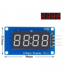
10 db 4 bites TM1637 piros digitális cső LED kijelző modul és óra Arduino LED B34-hez
843 Ft 1 533 FtThe module is a 12-foot clock with 4 points of positive digital (0.36 inches) display module driver IC TM1637, only two signal lines can make SCM four 8-segment LED.
Module features are as follows:
Display of male red for the four digital tube
Adjustable digital tube 8 gray
Level control interface for 5V or 3.3V
4 M2 screws positioning holes for easy installation
4 digital display interface module as shown below:
Control Interface: A total of four pins (GND, VCC, DIO, CLK), GND to ground, VCC is the power supply, DIO of data input and output pin, CLK is the clock signal pin;
Digital tube: 4 common anode score points with 0.36 inches LED, red highlights;
Positioning holes: 4 M2 screws positioning hole diameter is 2.2mm, the positioning of the module is easy to install, to achieve inter-module combination;
-
Szín: L9110S modul - L9110S DC léptetőmotor-vezérlőkártya H-híd léptetőmotor kettős egyenáramú motormodul a
105 Ft 191 Ft
Description:
Dimension: 3.2cm x 2.4cm x 1.8cm (approx)
Infrared sensor with control circuit board
The sensitivity and holding time can be adjusted
Working Voltage Range: DC 4.5V- 20V
Current drain:<60uA
Voltage Output: High/Low level signal:3.3V TTL output
Detection distance: 3--7M(can be adjusted)
Detection range: <140°
Delay time: 5-200S(can be adjusted, default 5s -3% )
Blockade time: 2.5 S (default)
Trigger: L: Non-repeatable trigger H: Repeat Trigger (default)
Work temperature:-20- 80°C
Trigger Method: L unrepeatable trigger / H repeatable trigger -
100K-(104) - 50 DB 3296W 3296 50 100 200 500 ohm 1K 2K 5K 10K 20K 50K 100K 200K 500K 1M ohm 103 100R 200R 500R Trimpot Trim
388 Ft 705 Ft3296W-1-100 (10R)
3296W-1-500 (50R)
3296W-1-101 (100R)
3296W-1-201 (200R)
3296W-1-501 (500R)
3296W-1-102 (1K)
3296W-1-202 (2K)
3296W-1-502 (5K)
3296W-1-103 (10K)
3296W-1-203 (20K)
3296W-1-503 (50K)
3296W-1-104 (100K)
3296W-1-204 (200K)
3296W-1-504 (500K)
3296W-1-105 (1M)
3296W-1-205 (2M) -
5V 16MHZ - 1 db Pro MINI 5V/16MHZ ATMEGA328 ATMEGA328P 5V 16M Arduino 3.3V/8MHZ kék verzióhoz
504 Ft 917 FtFeatures:
Condition: New
20 Digital input / output ports:TX, RX, D2 ~ D13, A0~A5
8 analog inputs ports:A0 ~ A7
1 pairs of TTL level serial transceiver ports RX / TX
6 PWM ports: D3, D5, D6, D9, D10, D11
Main ChipAtmel Atmega328P-AU
Support Serial Download
Support external power supply 3.8-12V DC
Support 12V or less than 12V battery power supply
16MHz clock frequency
Size: 33.8mm x 18mm
Color and more details are shown as pictures
PLS NOTE that due to lighting effects, monitor's brightness/ contrass settings ect,
there could be some slight differences in the color tone of the pictures and the actual item!
Package Included :
1 x PRO MINI -
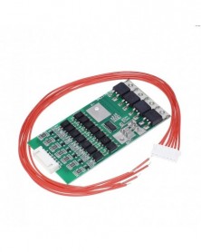
Bms 7S Li-ion Lithium 18650 akkumulátorvédő kártya 24V 20A akkumulátor kiegyensúlyozó megfelelő kábellel automatikus
526 Ft 957 FtBms 7S Li-ion Lithium 18650 Battery Protection Board 24V 20A Battery Balancer With Matching Cable Automatic Protection Function
100% brand new and high quality
Material: Electrical components
Color: See pictures
Equilibrium current: 80 mA(VCELL=4.20V)
Supported battery type: 7 cells 4.2V Lithium ion battery
Balancing the locus of control: 4.18±0.03 V
Overcharge threshold: 4.3±0.05 V
Overcharge time delay: 75mS
Overcharge release: 4.1±0.05 V
Discharge threshold: 2.4±0.08 V
Discharge delay: 5mS
Working current: 20 A
Over current threshold: 30 A
Static power: <500uA
Overcharge protection function:Yes
Discharge protection function:Yes
Over current protection function:Yes
Balanced protection function:Yes
Over-current release: Disconnect the load release
Short circuit protection function: Yes(Disconnect the load can be recovery.)
Feature:
This Lithium ion battery protection PCB protect single Lithium ion batteries.20A continous current.
Suitable for electric drills,motors,or aircraft models which require heavy current load.
Size: See the picture
No retail package -
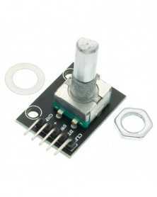
10db/tétel forgó kódoló modul tégla érzékelő fejlesztés arduino KY-040-hez
590 Ft 1 073 FtMaterial: Electronic components PCB
Size: About 31 * 19 * 29mm / 1.22" * 0.75" * 1.14"
Main color: Black
Working voltage: 5V
Pulse circle: 20
-
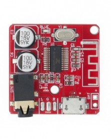
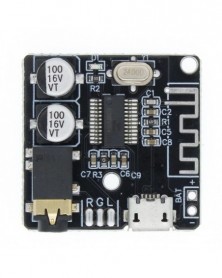
Szín: Bluetooth 4.1 - Bluetooth audio vevőkártya Bluetooth 4.1 BT5.0 Pro MP3 veszteségmentes dekóder kártya vezeték
158 Ft 287 FtBT5.0 Audio PRO Mini Bluetooth 5.0 MP3 Decoder Board Audio Receiver MP3 Lossless Player Wireless Stereo Music Amplifier Module Lithium battery charging Incoming call
BT5.0 Audio PRO continues the excellent basic functions of M28 (long-distance transmission, Bluetooth 5.0 backward compatible, lossless sound quality, etc.), and adds more user-friendly performance, as follows: Charge while putting: This product has a circuit of charging and discharging, which can directly charge the battery through the USB power supply, and Bluetooth can continue to work normally during the charging process, and truly realize the function of charging and discharging. Solve the pain point that some products can not be used during the charging process. When powered by USB alone: The red light flashes, indicating that the power supply is normal. When powered by a separate battery: The yellow light is always on, indicating that the battery power supply is normal; the yellow light flashes, indicating that the battery is low. When the USB and battery are connected at the same time: The red light flashes to indicate that the battery is charging; the red light always indicates that the battery is fully charged. (Note that if the USB input is suddenly disconnected during the charging and discharging process, there will be a few seconds of interruption due
to the charge and discharge mode switching at this time, after which Bluetooth will automatically restart, automatically connect and maintain the previous playback state) Incoming voice call function: After the Bluetooth is connected, turn on the call audio mode in the Bluetooth settings. If the phone calls, you can answer or hang up the phone through the PLAY/STOP button. You can choose to send from the microphone of the original headset (provided that the headset has a call function, which is a 4-segment type) or from the onboard microphone (default), see the function description for details. When the computer sound card is used: Tin the pads in the two boxes corresponding to the Sound Card on the back of the module, and then connect it to the USB interface of the computer through the USB cable, which can be used as a sound card. That is, the sound played by the computer is output through the audio interface of the module. See function description for details. (Not enabled by default) Product Size:
Product Features:
Support bluetooth 4.1 Mode, Support automatically back to even, Support to decode WAV/APE/FLAC/MP3 files losslessly, Support to output stereo.
Parameters characteristics
Power Supply
3.7-5V
SNR
90dB
THD N
-70dB
Crosstalk
-86dB
DNR
91dB
Support Profile
A2DP/AVCTP/AVDTP/AVRCP/HFP
LOS
>15m
Functions and interfaces defination:
2.Interface details
USB powered
Universal Micro USB 5V power supply
3.7-5V Supply Pad
External 3.7-5V lithium battery power conversion
LED indicator
Bluetooth mode long blue light
3.5mm stereo audio interface
Standard 3.5mm interface, output stereo sound source, plug in headphones, connect amplifiers and other devices
Instructions:
After the power is turned on, the blue indicator lights up and enters the Bluetooth mode; the English “The bluetooth device is ready to pair” is displayed, indicating that the Bluetooth mode is entered and waiting for pairing; the “XY_BT” searched by the mobile phone Bluetooth is the device name of the decoding board. , Click on the connection, the decoder board prompts "The bluetooth device is connected successfully", indicating that the decoder board and the mobile phone are connected successfully, you can play music. As shown below Picture;
-
Szín: Bluetooth 5.0 - Bluetooth audio vevőkártya Bluetooth 4.1 BT5.0 Pro MP3 veszteségmentes dekóder kártya vezeték
158 Ft 287 FtBT5.0 Audio PRO Mini Bluetooth 5.0 MP3 Decoder Board Audio Receiver MP3 Lossless Player Wireless Stereo Music Amplifier Module Lithium battery charging Incoming call
BT5.0 Audio PRO continues the excellent basic functions of M28 (long-distance transmission, Bluetooth 5.0 backward compatible, lossless sound quality, etc.), and adds more user-friendly performance, as follows: Charge while putting: This product has a circuit of charging and discharging, which can directly charge the battery through the USB power supply, and Bluetooth can continue to work normally during the charging process, and truly realize the function of charging and discharging. Solve the pain point that some products can not be used during the charging process. When powered by USB alone: The red light flashes, indicating that the power supply is normal. When powered by a separate battery: The yellow light is always on, indicating that the battery power supply is normal; the yellow light flashes, indicating that the battery is low. When the USB and battery are connected at the same time: The red light flashes to indicate that the battery is charging; the red light always indicates that the battery is fully charged. (Note that if the USB input is suddenly disconnected during the charging and discharging process, there will be a few seconds of interruption due
to the charge and discharge mode switching at this time, after which Bluetooth will automatically restart, automatically connect and maintain the previous playback state) Incoming voice call function: After the Bluetooth is connected, turn on the call audio mode in the Bluetooth settings. If the phone calls, you can answer or hang up the phone through the PLAY/STOP button. You can choose to send from the microphone of the original headset (provided that the headset has a call function, which is a 4-segment type) or from the onboard microphone (default), see the function description for details. When the computer sound card is used: Tin the pads in the two boxes corresponding to the Sound Card on the back of the module, and then connect it to the USB interface of the computer through the USB cable, which can be used as a sound card. That is, the sound played by the computer is output through the audio interface of the module. See function description for details. (Not enabled by default) Product Size:
Product Features:
Support bluetooth 4.1 Mode, Support automatically back to even, Support to decode WAV/APE/FLAC/MP3 files losslessly, Support to output stereo.
Parameters characteristics
Power Supply
3.7-5V
SNR
90dB
THD N
-70dB
Crosstalk
-86dB
DNR
91dB
Support Profile
A2DP/AVCTP/AVDTP/AVRCP/HFP
LOS
>15m
Functions and interfaces defination:
2.Interface details
USB powered
Universal Micro USB 5V power supply
3.7-5V Supply Pad
External 3.7-5V lithium battery power conversion
LED indicator
Bluetooth mode long blue light
3.5mm stereo audio interface
Standard 3.5mm interface, output stereo sound source, plug in headphones, connect amplifiers and other devices
Instructions:
After the power is turned on, the blue indicator lights up and enters the Bluetooth mode; the English “The bluetooth device is ready to pair” is displayed, indicating that the Bluetooth mode is entered and waiting for pairing; the “XY_BT” searched by the mobile phone Bluetooth is the device name of the decoding board. , Click on the connection, the decoder board prompts "The bluetooth device is connected successfully", indicating that the decoder board and the mobile phone are connected successfully, you can play music. As shown below Picture;
-
Szín: BT5.0-Pro - Bluetooth audio vevőkártya Bluetooth 4.1 BT5.0 Pro MP3 veszteségmentes dekóder kártya vezeték nélküli
255 Ft 463 FtBT5.0 Audio PRO Mini Bluetooth 5.0 MP3 Decoder Board Audio Receiver MP3 Lossless Player Wireless Stereo Music Amplifier Module Lithium battery charging Incoming call
BT5.0 Audio PRO continues the excellent basic functions of M28 (long-distance transmission, Bluetooth 5.0 backward compatible, lossless sound quality, etc.), and adds more user-friendly performance, as follows: Charge while putting: This product has a circuit of charging and discharging, which can directly charge the battery through the USB power supply, and Bluetooth can continue to work normally during the charging process, and truly realize the function of charging and discharging. Solve the pain point that some products can not be used during the charging process. When powered by USB alone: The red light flashes, indicating that the power supply is normal. When powered by a separate battery: The yellow light is always on, indicating that the battery power supply is normal; the yellow light flashes, indicating that the battery is low. When the USB and battery are connected at the same time: The red light flashes to indicate that the battery is charging; the red light always indicates that the battery is fully charged. (Note that if the USB input is suddenly disconnected during the charging and discharging process, there will be a few seconds of interruption due
to the charge and discharge mode switching at this time, after which Bluetooth will automatically restart, automatically connect and maintain the previous playback state) Incoming voice call function: After the Bluetooth is connected, turn on the call audio mode in the Bluetooth settings. If the phone calls, you can answer or hang up the phone through the PLAY/STOP button. You can choose to send from the microphone of the original headset (provided that the headset has a call function, which is a 4-segment type) or from the onboard microphone (default), see the function description for details. When the computer sound card is used: Tin the pads in the two boxes corresponding to the Sound Card on the back of the module, and then connect it to the USB interface of the computer through the USB cable, which can be used as a sound card. That is, the sound played by the computer is output through the audio interface of the module. See function description for details. (Not enabled by default) Product Size:
Product Features:
Support bluetooth 4.1 Mode, Support automatically back to even, Support to decode WAV/APE/FLAC/MP3 files losslessly, Support to output stereo.
Parameters characteristics
Power Supply
3.7-5V
SNR
90dB
THD N
-70dB
Crosstalk
-86dB
DNR
91dB
Support Profile
A2DP/AVCTP/AVDTP/AVRCP/HFP
LOS
>15m
Functions and interfaces defination:
2.Interface details
USB powered
Universal Micro USB 5V power supply
3.7-5V Supply Pad
External 3.7-5V lithium battery power conversion
LED indicator
Bluetooth mode long blue light
3.5mm stereo audio interface
Standard 3.5mm interface, output stereo sound source, plug in headphones, connect amplifiers and other devices
Instructions:
After the power is turned on, the blue indicator lights up and enters the Bluetooth mode; the English “The bluetooth device is ready to pair” is displayed, indicating that the Bluetooth mode is entered and waiting for pairing; the “XY_BT” searched by the mobile phone Bluetooth is the device name of the decoding board. , Click on the connection, the decoder board prompts "The bluetooth device is connected successfully", indicating that the decoder board and the mobile phone are connected successfully, you can play music. As shown below Picture;
-
Szín: BT5.0 tokkal - Bluetooth audio vevőkártya Bluetooth 4.1 BT5.0 Pro MP3 veszteségmentes dekóder kártya vezeték
228 Ft 415 FtBT5.0 Audio PRO Mini Bluetooth 5.0 MP3 Decoder Board Audio Receiver MP3 Lossless Player Wireless Stereo Music Amplifier Module Lithium battery charging Incoming call
BT5.0 Audio PRO continues the excellent basic functions of M28 (long-distance transmission, Bluetooth 5.0 backward compatible, lossless sound quality, etc.), and adds more user-friendly performance, as follows: Charge while putting: This product has a circuit of charging and discharging, which can directly charge the battery through the USB power supply, and Bluetooth can continue to work normally during the charging process, and truly realize the function of charging and discharging. Solve the pain point that some products can not be used during the charging process. When powered by USB alone: The red light flashes, indicating that the power supply is normal. When powered by a separate battery: The yellow light is always on, indicating that the battery power supply is normal; the yellow light flashes, indicating that the battery is low. When the USB and battery are connected at the same time: The red light flashes to indicate that the battery is charging; the red light always indicates that the battery is fully charged. (Note that if the USB input is suddenly disconnected during the charging and discharging process, there will be a few seconds of interruption due
to the charge and discharge mode switching at this time, after which Bluetooth will automatically restart, automatically connect and maintain the previous playback state) Incoming voice call function: After the Bluetooth is connected, turn on the call audio mode in the Bluetooth settings. If the phone calls, you can answer or hang up the phone through the PLAY/STOP button. You can choose to send from the microphone of the original headset (provided that the headset has a call function, which is a 4-segment type) or from the onboard microphone (default), see the function description for details. When the computer sound card is used: Tin the pads in the two boxes corresponding to the Sound Card on the back of the module, and then connect it to the USB interface of the computer through the USB cable, which can be used as a sound card. That is, the sound played by the computer is output through the audio interface of the module. See function description for details. (Not enabled by default) Product Size:
Product Features:
Support bluetooth 4.1 Mode, Support automatically back to even, Support to decode WAV/APE/FLAC/MP3 files losslessly, Support to output stereo.
Parameters characteristics
Power Supply
3.7-5V
SNR
90dB
THD N
-70dB
Crosstalk
-86dB
DNR
91dB
Support Profile
A2DP/AVCTP/AVDTP/AVRCP/HFP
LOS
>15m
Functions and interfaces defination:
2.Interface details
USB powered
Universal Micro USB 5V power supply
3.7-5V Supply Pad
External 3.7-5V lithium battery power conversion
LED indicator
Bluetooth mode long blue light
3.5mm stereo audio interface
Standard 3.5mm interface, output stereo sound source, plug in headphones, connect amplifiers and other devices
Instructions:
After the power is turned on, the blue indicator lights up and enters the Bluetooth mode; the English “The bluetooth device is ready to pair” is displayed, indicating that the Bluetooth mode is entered and waiting for pairing; the “XY_BT” searched by the mobile phone Bluetooth is the device name of the decoding board. , Click on the connection, the decoder board prompts "The bluetooth device is connected successfully", indicating that the decoder board and the mobile phone are connected successfully, you can play music. As shown below Picture;
-
Szín: BT5.0 Pro tokkal - Bluetooth audio vevőkártya Bluetooth 4.1 BT5.0 Pro MP3 veszteségmentes dekóder kártya vezeték
324 Ft 589 FtBT5.0 Audio PRO Mini Bluetooth 5.0 MP3 Decoder Board Audio Receiver MP3 Lossless Player Wireless Stereo Music Amplifier Module Lithium battery charging Incoming call
BT5.0 Audio PRO continues the excellent basic functions of M28 (long-distance transmission, Bluetooth 5.0 backward compatible, lossless sound quality, etc.), and adds more user-friendly performance, as follows: Charge while putting: This product has a circuit of charging and discharging, which can directly charge the battery through the USB power supply, and Bluetooth can continue to work normally during the charging process, and truly realize the function of charging and discharging. Solve the pain point that some products can not be used during the charging process. When powered by USB alone: The red light flashes, indicating that the power supply is normal. When powered by a separate battery: The yellow light is always on, indicating that the battery power supply is normal; the yellow light flashes, indicating that the battery is low. When the USB and battery are connected at the same time: The red light flashes to indicate that the battery is charging; the red light always indicates that the battery is fully charged. (Note that if the USB input is suddenly disconnected during the charging and discharging process, there will be a few seconds of interruption due
to the charge and discharge mode switching at this time, after which Bluetooth will automatically restart, automatically connect and maintain the previous playback state) Incoming voice call function: After the Bluetooth is connected, turn on the call audio mode in the Bluetooth settings. If the phone calls, you can answer or hang up the phone through the PLAY/STOP button. You can choose to send from the microphone of the original headset (provided that the headset has a call function, which is a 4-segment type) or from the onboard microphone (default), see the function description for details. When the computer sound card is used: Tin the pads in the two boxes corresponding to the Sound Card on the back of the module, and then connect it to the USB interface of the computer through the USB cable, which can be used as a sound card. That is, the sound played by the computer is output through the audio interface of the module. See function description for details. (Not enabled by default) Product Size:
Product Features:
Support bluetooth 4.1 Mode, Support automatically back to even, Support to decode WAV/APE/FLAC/MP3 files losslessly, Support to output stereo.
Parameters characteristics
Power Supply
3.7-5V
SNR
90dB
THD N
-70dB
Crosstalk
-86dB
DNR
91dB
Support Profile
A2DP/AVCTP/AVDTP/AVRCP/HFP
LOS
>15m
Functions and interfaces defination:
2.Interface details
USB powered
Universal Micro USB 5V power supply
3.7-5V Supply Pad
External 3.7-5V lithium battery power conversion
LED indicator
Bluetooth mode long blue light
3.5mm stereo audio interface
Standard 3.5mm interface, output stereo sound source, plug in headphones, connect amplifiers and other devices
Instructions:
After the power is turned on, the blue indicator lights up and enters the Bluetooth mode; the English “The bluetooth device is ready to pair” is displayed, indicating that the Bluetooth mode is entered and waiting for pairing; the “XY_BT” searched by the mobile phone Bluetooth is the device name of the decoding board. , Click on the connection, the decoder board prompts "The bluetooth device is connected successfully", indicating that the decoder board and the mobile phone are connected successfully, you can play music. As shown below Picture;
-
1db ENC28J60 Ethernet Shield V1.0 kompatibilis Nano 3.0 RJ45 webszerver modul Arduinohoz
636 Ft 1 156 FtEthernet Shield Nano UNO R3, work as ENC28J60 RJ45 Webserver
Description
100% Brand new
With this Ethernet Shield, Nano board can be used to connect to internet
controller: Microchip's ENC28J60 ethernet / HR911105A
works as server or client
comes with efficient library and examples
direct plug puzzle board, NO soldering needed -
10 DB legújabb többfunkciós mini boost modul Step Up kártya 5V/8V/9V/12V 1,5A LED jelző Diy elektronikus feszültségmodul
541 Ft 984 FtMulti-function mini boost module
Basic parameters
The output voltage can be set to 5V/8V/9V/12V, the default is 12V
Input voltage range: 2.5V~VOUT-0.5V
Output performance: Take 3.7V lithium battery input as an example, it can output 5V1.2A, 8V0.7A, 9V0.6A, 12V0.5A. Make sure that the input current and output current do not exceed 1.5A.
Voltage setting description
The front side of the PCB can be seen with the words A and B. The output voltage can be changed by using the soldering iron to change the pad on and off. In the following table, 0 means the pad is disconnected and 1 means the pad is connected.
A B VOUT
0 0 5V 0 1 8V
1 0 9V
1 1 12V
The pad next to the LED indicator can also be turned off to turn off the indicator.
Product size: 22 × 11 × 3.6mm
-
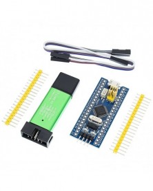
Szín: STM32F103C8T6 - STM32F103C8T6 ARM STM32 Minimális rendszerfejlesztő kártyamodul Arduino barkácskészlethez ST-Link
327 Ft 595 FtProduct Introduction
This is a core chip based on for CS32F103C8T6 ARM core board, features are as follows:
1, the board based on the most basic MCU circuit, 8M and 32768 crystal circuit, USB power supply circuit.
2, the core board is divided into two rows leads to all the I / O port.
3, with SWD simulation debug download interface, simple and convenient, debugging speed.
4, the use of the Mirco USB interface, you can do USB communication and power supply, USB interface, compatible with the ordinary Andrews mobile phone charger interface.
6, RTC crystal Epson brand, easy to start, more stable.
7, with double pin, but the pin does not default welding, the user according to their own application scenarios to choose their own welding direction. If welding is required, please tell the owner.
Keil can be used to compile, IAR compiler, can be downloaded through the J-Link or USART1 procedures, the procedures are the owner and debugging procedures, there are problems can consult the owner.
Chip Description:
1, 32F103C8T6
Package Type: LQFP;
Number of pins: 48;
Kernel: Cortex-M3;
Operating frequency: 72MHz;
Storage resources: 64K Byte Flash, 20KByte SRAM;
Interface Resources: 2x SPI, 3x USART, 2x I2C, 1x CAN, 37x I / O ports,
Analog-to-digital conversion: 2x ADC (12-bit / 16-channel)
Timers: 3 general timers and 1 advanced timer
Debug Download: Support JTAG / SWD debug interface to download, support for IAP.
2, RT9193: 3.3V regulator chip, the maximum output of 300mA.
Interface description:
1, SWD interface: support for simulation, download and debug.
2, Mirco USB interface: power supply and USB communication, does not support the download.
3, USART1 interface: USART1 can be used to download the program, or use the USART1 for communication.
4, MCU pin interface: leads all I / O port pins, easy to connect with peripherals.
5, 5V and 3.3V power input and output interface: commonly used in external power supply, or with other modules for common ground treatment
Other Device Description:
1, Power LED (PWR): Power indicator status, can determine whether the power supply is stable.
2, the user LED (PC13): to facilitate the I / O output test or indicate the program running.
3, start jumping choose programming mode: (1, the user flash memory 2, SRAM 3, system memory).
4, reset button: reset chip for the user program.
5, 8M Crystal: The frequency can be set to make the system clocked at 72MHz.
6,32.768KHz Crystal: Available for built-in RTC, or for calibration. -
Szín: ST-LINK V2 - STM32F103C8T6 ARM STM32 Minimális rendszerfejlesztő kártyamodul Arduino barkácskészlethez ST-Link V2
327 Ft 595 FtProduct Introduction
This is a core chip based on for CS32F103C8T6 ARM core board, features are as follows:
1, the board based on the most basic MCU circuit, 8M and 32768 crystal circuit, USB power supply circuit.
2, the core board is divided into two rows leads to all the I / O port.
3, with SWD simulation debug download interface, simple and convenient, debugging speed.
4, the use of the Mirco USB interface, you can do USB communication and power supply, USB interface, compatible with the ordinary Andrews mobile phone charger interface.
6, RTC crystal Epson brand, easy to start, more stable.
7, with double pin, but the pin does not default welding, the user according to their own application scenarios to choose their own welding direction. If welding is required, please tell the owner.
Keil can be used to compile, IAR compiler, can be downloaded through the J-Link or USART1 procedures, the procedures are the owner and debugging procedures, there are problems can consult the owner.
Chip Description:
1, 32F103C8T6
Package Type: LQFP;
Number of pins: 48;
Kernel: Cortex-M3;
Operating frequency: 72MHz;
Storage resources: 64K Byte Flash, 20KByte SRAM;
Interface Resources: 2x SPI, 3x USART, 2x I2C, 1x CAN, 37x I / O ports,
Analog-to-digital conversion: 2x ADC (12-bit / 16-channel)
Timers: 3 general timers and 1 advanced timer
Debug Download: Support JTAG / SWD debug interface to download, support for IAP.
2, RT9193: 3.3V regulator chip, the maximum output of 300mA.
Interface description:
1, SWD interface: support for simulation, download and debug.
2, Mirco USB interface: power supply and USB communication, does not support the download.
3, USART1 interface: USART1 can be used to download the program, or use the USART1 for communication.
4, MCU pin interface: leads all I / O port pins, easy to connect with peripherals.
5, 5V and 3.3V power input and output interface: commonly used in external power supply, or with other modules for common ground treatment
Other Device Description:
1, Power LED (PWR): Power indicator status, can determine whether the power supply is stable.
2, the user LED (PC13): to facilitate the I / O output test or indicate the program running.
3, start jumping choose programming mode: (1, the user flash memory 2, SRAM 3, system memory).
4, reset button: reset chip for the user program.
5, 8M Crystal: The frequency can be set to make the system clocked at 72MHz.
6,32.768KHz Crystal: Available for built-in RTC, or for calibration. -
Szín: 1 SZETT - STM32F103C8T6 ARM STM32 Minimális rendszerfejlesztő kártyamodul Arduino barkácskészlethez ST-Link V2
568 Ft 1 032 FtProduct Introduction
This is a core chip based on for CS32F103C8T6 ARM core board, features are as follows:
1, the board based on the most basic MCU circuit, 8M and 32768 crystal circuit, USB power supply circuit.
2, the core board is divided into two rows leads to all the I / O port.
3, with SWD simulation debug download interface, simple and convenient, debugging speed.
4, the use of the Mirco USB interface, you can do USB communication and power supply, USB interface, compatible with the ordinary Andrews mobile phone charger interface.
6, RTC crystal Epson brand, easy to start, more stable.
7, with double pin, but the pin does not default welding, the user according to their own application scenarios to choose their own welding direction. If welding is required, please tell the owner.
Keil can be used to compile, IAR compiler, can be downloaded through the J-Link or USART1 procedures, the procedures are the owner and debugging procedures, there are problems can consult the owner.
Chip Description:
1, 32F103C8T6
Package Type: LQFP;
Number of pins: 48;
Kernel: Cortex-M3;
Operating frequency: 72MHz;
Storage resources: 64K Byte Flash, 20KByte SRAM;
Interface Resources: 2x SPI, 3x USART, 2x I2C, 1x CAN, 37x I / O ports,
Analog-to-digital conversion: 2x ADC (12-bit / 16-channel)
Timers: 3 general timers and 1 advanced timer
Debug Download: Support JTAG / SWD debug interface to download, support for IAP.
2, RT9193: 3.3V regulator chip, the maximum output of 300mA.
Interface description:
1, SWD interface: support for simulation, download and debug.
2, Mirco USB interface: power supply and USB communication, does not support the download.
3, USART1 interface: USART1 can be used to download the program, or use the USART1 for communication.
4, MCU pin interface: leads all I / O port pins, easy to connect with peripherals.
5, 5V and 3.3V power input and output interface: commonly used in external power supply, or with other modules for common ground treatment
Other Device Description:
1, Power LED (PWR): Power indicator status, can determine whether the power supply is stable.
2, the user LED (PC13): to facilitate the I / O output test or indicate the program running.
3, start jumping choose programming mode: (1, the user flash memory 2, SRAM 3, system memory).
4, reset button: reset chip for the user program.
5, 8M Crystal: The frequency can be set to make the system clocked at 72MHz.
6,32.768KHz Crystal: Available for built-in RTC, or for calibration. -
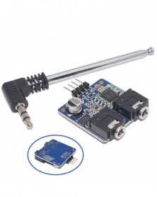
1 db TEA5767 FM sztereó rádió modul Arduino rádióhoz 76-108MHZ ingyenes kábelantennával raktáron
456 Ft 829 Ftpower supply: 5V
Frequency range: 76-108MHZ
PCB size: 31*30mm
With reverse polarity protection diode
With power output filtering sensor
Directly plug antenna interface
I2C bus communication
Multi capacitor combined filter
Blue LED power indicator
FM chip module TEA5767
Onboard 3.5mm audio interface
If connects with singlechip, only connect the Power Ground and two I2C communication cable
Features:
LC harmonic oscillator use low cost fixed chip
No need to adjust Intermediate frequency
High sensitivity(low noise RF input amplifier)
High power auto gain control AGC circuit
Soft mute -
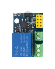
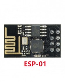
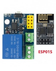
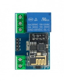
Szín: Relé modul - ESP8266 ESP-01 ESP-01S 5V WiFi relé modul Dolgok Smart Home Távirányító Kapcsoló Telefon APP Vezeték
153 Ft 278 Ft
ESP8266 5V Wifi Relay Module
Product parameters:
Product size: 45*28mm
Working voltage: DC5V
Communication method: WIFI (ESP8266 module)
Serial communication parameters: 9600,8,1,0,0
Transmission distance: The maximum transmission distance is 400m (in an open environment, when the mobile phone is equipped with a WIFI module)
Load: 10A/250VAC 10A/30VDC, the relay pulls 100,000 times
Way of working:
1. The mobile phone is mounted on the WiFi module;
2. The mobile phone and WiFI module are mounted on the same router, and the relay is controlled through the mobile APP; the transmission distance in this mode depends on the signal of the router.
1. The onboard ESP8266 WIFI module has three working modes: STA (client), AP (hotspot), and STA AP (client hotspot). Choose the working mode of the WIFI module according to the working mode of the module. .
2. Before using the module, you need to use the serial port debugging software and the USB to TTL module to send serial commands to configure the WIFI module. The RX, TX, and GND pins of the USB to TTL module are connected to the TX, RX, and GND pins on the module (ESP8266 The default baud rate of the module is generally 115200 or 9600. When it is 115200, you need to send AT CIOBAUD=9600 to set the baud rate to 9600, otherwise the relay cannot be controlled correctly), IN , IN- connect to 5V power supply.
3. After the configuration is complete (note that the 5V power supply cannot be unplugged, because some parameters of the WIFI module cannot be saved after the power is off), install the "TCP connection" APP on the Android phone, open it and click "Connect", enter the IP address and port number , Click "connect", then click "switch" in the interface, long press the gray square in the interface to add a serial port command, enter the name and content of the command (when the command content is A00101A2, turn on the relay; when the command content is A00100A1, turn off the relay) And choose to send in hexadecimal format, and then click the corresponding box to control the switch of the relay. The specific configuration method of the WIFI module is as follows:
Working method 1: When the mobile phone is mounted on the WiFi module, the commands are sent in the following order:
1. AT CWMODE=2, namely select AP mode;
2. AT RST, reset;
3. AT CIPMUX=1, open multiple connections;
4. AT CIPSERVER=1,8080, configure the TCP server and set the port number;
5. AT CIOBAUD=9600, set the baud rate to 9600. (Because the relay control chip works at the baud rate 9600)
6. AT CIFSR, check the IP address in AP mode, for example: APIP, "192.168.4.1";
7. The WIFI signal whose mobile phone connection name starts with AI-THINKER or ESP8266;
8. Enter the address and port in the "TCP connection" APP, such as 192.168.4.1 and 8080;
9. Click the corresponding gray square to control the relay.
Working mode 2: When the mobile phone and the WiFI module are simultaneously mounted on the same router, the commands are sent in the following order:
1. AT CWMODE=1, that is, select STA mode;
2. AT RST, reset;
3. AT CWLAP, list available WIFI nearby;
4. AT CWJAP=,, let the WiFi module connect to the router, where ssid
And password are the WIFI name and password, for example: AT CWJAP="TP-LINK","123456";
5. AT CIPMUX=1, open multiple connections;
6. AT CIPSERVER=1,8080, configure the TCP server and set the port number;
7. AT CIFSR, check the IP address in STA mode, for example: STAIP, "192.168.1.102";
8. Connect the mobile phone to the router;
9. Enter the address and port in the "TCP connection" APP, for example: 192.168.1.102 and 8080;
10. Click the corresponding gray square to control the relay.
Tips:
1. The STA AP mode of the WIFI module is applicable to the above two working methods.
2. The ESP8266 module has a timeout mechanism. When the phone does not send instructions to the module for a period of time (default 180S), the module will kick the phone off. You can send AT CIPSTO= on the computer to modify this time ( The time range is 0-7200), such as: AT CIPSTO=3600.
3. When the WIFI module on the module is unplugged, the RX, TX and GND pins of the USB to TTL module are connected to the RX, TX and GND pins on the module respectively, and IN and IN- are connected to the 5V power supply, and the module can be used as A USB relay is used, with strong scalability -
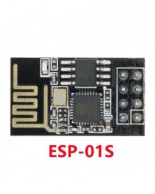
Szín: ESP01 - ESP8266 ESP-01 ESP-01S 5V WiFi relé modul Dolgok Smart Home Távirányító Kapcsoló Telefon APP Vezeték
174 Ft 316 Ft
ESP8266 5V Wifi Relay Module
Product parameters:
Product size: 45*28mm
Working voltage: DC5V
Communication method: WIFI (ESP8266 module)
Serial communication parameters: 9600,8,1,0,0
Transmission distance: The maximum transmission distance is 400m (in an open environment, when the mobile phone is equipped with a WIFI module)
Load: 10A/250VAC 10A/30VDC, the relay pulls 100,000 times
Way of working:
1. The mobile phone is mounted on the WiFi module;
2. The mobile phone and WiFI module are mounted on the same router, and the relay is controlled through the mobile APP; the transmission distance in this mode depends on the signal of the router.
1. The onboard ESP8266 WIFI module has three working modes: STA (client), AP (hotspot), and STA AP (client hotspot). Choose the working mode of the WIFI module according to the working mode of the module. .
2. Before using the module, you need to use the serial port debugging software and the USB to TTL module to send serial commands to configure the WIFI module. The RX, TX, and GND pins of the USB to TTL module are connected to the TX, RX, and GND pins on the module (ESP8266 The default baud rate of the module is generally 115200 or 9600. When it is 115200, you need to send AT CIOBAUD=9600 to set the baud rate to 9600, otherwise the relay cannot be controlled correctly), IN , IN- connect to 5V power supply.
3. After the configuration is complete (note that the 5V power supply cannot be unplugged, because some parameters of the WIFI module cannot be saved after the power is off), install the "TCP connection" APP on the Android phone, open it and click "Connect", enter the IP address and port number , Click "connect", then click "switch" in the interface, long press the gray square in the interface to add a serial port command, enter the name and content of the command (when the command content is A00101A2, turn on the relay; when the command content is A00100A1, turn off the relay) And choose to send in hexadecimal format, and then click the corresponding box to control the switch of the relay. The specific configuration method of the WIFI module is as follows:
Working method 1: When the mobile phone is mounted on the WiFi module, the commands are sent in the following order:
1. AT CWMODE=2, namely select AP mode;
2. AT RST, reset;
3. AT CIPMUX=1, open multiple connections;
4. AT CIPSERVER=1,8080, configure the TCP server and set the port number;
5. AT CIOBAUD=9600, set the baud rate to 9600. (Because the relay control chip works at the baud rate 9600)
6. AT CIFSR, check the IP address in AP mode, for example: APIP, "192.168.4.1";
7. The WIFI signal whose mobile phone connection name starts with AI-THINKER or ESP8266;
8. Enter the address and port in the "TCP connection" APP, such as 192.168.4.1 and 8080;
9. Click the corresponding gray square to control the relay.
Working mode 2: When the mobile phone and the WiFI module are simultaneously mounted on the same router, the commands are sent in the following order:
1. AT CWMODE=1, that is, select STA mode;
2. AT RST, reset;
3. AT CWLAP, list available WIFI nearby;
4. AT CWJAP=,, let the WiFi module connect to the router, where ssid
And password are the WIFI name and password, for example: AT CWJAP="TP-LINK","123456";
5. AT CIPMUX=1, open multiple connections;
6. AT CIPSERVER=1,8080, configure the TCP server and set the port number;
7. AT CIFSR, check the IP address in STA mode, for example: STAIP, "192.168.1.102";
8. Connect the mobile phone to the router;
9. Enter the address and port in the "TCP connection" APP, for example: 192.168.1.102 and 8080;
10. Click the corresponding gray square to control the relay.
Tips:
1. The STA AP mode of the WIFI module is applicable to the above two working methods.
2. The ESP8266 module has a timeout mechanism. When the phone does not send instructions to the module for a period of time (default 180S), the module will kick the phone off. You can send AT CIPSTO= on the computer to modify this time ( The time range is 0-7200), such as: AT CIPSTO=3600.
3. When the WIFI module on the module is unplugged, the RX, TX and GND pins of the USB to TTL module are connected to the RX, TX and GND pins on the module respectively, and IN and IN- are connected to the 5V power supply, and the module can be used as A USB relay is used, with strong scalability -
Szín: ESP01S - ESP8266 ESP-01 ESP-01S 5V WiFi relé modul Dolgok Smart Home Távirányító Kapcsoló Telefon APP Vezeték
174 Ft 316 Ft
ESP8266 5V Wifi Relay Module
Product parameters:
Product size: 45*28mm
Working voltage: DC5V
Communication method: WIFI (ESP8266 module)
Serial communication parameters: 9600,8,1,0,0
Transmission distance: The maximum transmission distance is 400m (in an open environment, when the mobile phone is equipped with a WIFI module)
Load: 10A/250VAC 10A/30VDC, the relay pulls 100,000 times
Way of working:
1. The mobile phone is mounted on the WiFi module;
2. The mobile phone and WiFI module are mounted on the same router, and the relay is controlled through the mobile APP; the transmission distance in this mode depends on the signal of the router.
1. The onboard ESP8266 WIFI module has three working modes: STA (client), AP (hotspot), and STA AP (client hotspot). Choose the working mode of the WIFI module according to the working mode of the module. .
2. Before using the module, you need to use the serial port debugging software and the USB to TTL module to send serial commands to configure the WIFI module. The RX, TX, and GND pins of the USB to TTL module are connected to the TX, RX, and GND pins on the module (ESP8266 The default baud rate of the module is generally 115200 or 9600. When it is 115200, you need to send AT CIOBAUD=9600 to set the baud rate to 9600, otherwise the relay cannot be controlled correctly), IN , IN- connect to 5V power supply.
3. After the configuration is complete (note that the 5V power supply cannot be unplugged, because some parameters of the WIFI module cannot be saved after the power is off), install the "TCP connection" APP on the Android phone, open it and click "Connect", enter the IP address and port number , Click "connect", then click "switch" in the interface, long press the gray square in the interface to add a serial port command, enter the name and content of the command (when the command content is A00101A2, turn on the relay; when the command content is A00100A1, turn off the relay) And choose to send in hexadecimal format, and then click the corresponding box to control the switch of the relay. The specific configuration method of the WIFI module is as follows:
Working method 1: When the mobile phone is mounted on the WiFi module, the commands are sent in the following order:
1. AT CWMODE=2, namely select AP mode;
2. AT RST, reset;
3. AT CIPMUX=1, open multiple connections;
4. AT CIPSERVER=1,8080, configure the TCP server and set the port number;
5. AT CIOBAUD=9600, set the baud rate to 9600. (Because the relay control chip works at the baud rate 9600)
6. AT CIFSR, check the IP address in AP mode, for example: APIP, "192.168.4.1";
7. The WIFI signal whose mobile phone connection name starts with AI-THINKER or ESP8266;
8. Enter the address and port in the "TCP connection" APP, such as 192.168.4.1 and 8080;
9. Click the corresponding gray square to control the relay.
Working mode 2: When the mobile phone and the WiFI module are simultaneously mounted on the same router, the commands are sent in the following order:
1. AT CWMODE=1, that is, select STA mode;
2. AT RST, reset;
3. AT CWLAP, list available WIFI nearby;
4. AT CWJAP=,, let the WiFi module connect to the router, where ssid
And password are the WIFI name and password, for example: AT CWJAP="TP-LINK","123456";
5. AT CIPMUX=1, open multiple connections;
6. AT CIPSERVER=1,8080, configure the TCP server and set the port number;
7. AT CIFSR, check the IP address in STA mode, for example: STAIP, "192.168.1.102";
8. Connect the mobile phone to the router;
9. Enter the address and port in the "TCP connection" APP, for example: 192.168.1.102 and 8080;
10. Click the corresponding gray square to control the relay.
Tips:
1. The STA AP mode of the WIFI module is applicable to the above two working methods.
2. The ESP8266 module has a timeout mechanism. When the phone does not send instructions to the module for a period of time (default 180S), the module will kick the phone off. You can send AT CIPSTO= on the computer to modify this time ( The time range is 0-7200), such as: AT CIPSTO=3600.
3. When the WIFI module on the module is unplugged, the RX, TX and GND pins of the USB to TTL module are connected to the RX, TX and GND pins on the module respectively, and IN and IN- are connected to the 5V power supply, and the module can be used as A USB relay is used, with strong scalability -
Szín: ESP01-es modul - ESP8266 ESP-01 ESP-01S 5V WiFi relé modul Dolgok Smart Home Távirányító Kapcsoló Telefon APP
248 Ft 450 Ft
ESP8266 5V Wifi Relay Module
Product parameters:
Product size: 45*28mm
Working voltage: DC5V
Communication method: WIFI (ESP8266 module)
Serial communication parameters: 9600,8,1,0,0
Transmission distance: The maximum transmission distance is 400m (in an open environment, when the mobile phone is equipped with a WIFI module)
Load: 10A/250VAC 10A/30VDC, the relay pulls 100,000 times
Way of working:
1. The mobile phone is mounted on the WiFi module;
2. The mobile phone and WiFI module are mounted on the same router, and the relay is controlled through the mobile APP; the transmission distance in this mode depends on the signal of the router.
1. The onboard ESP8266 WIFI module has three working modes: STA (client), AP (hotspot), and STA AP (client hotspot). Choose the working mode of the WIFI module according to the working mode of the module. .
2. Before using the module, you need to use the serial port debugging software and the USB to TTL module to send serial commands to configure the WIFI module. The RX, TX, and GND pins of the USB to TTL module are connected to the TX, RX, and GND pins on the module (ESP8266 The default baud rate of the module is generally 115200 or 9600. When it is 115200, you need to send AT CIOBAUD=9600 to set the baud rate to 9600, otherwise the relay cannot be controlled correctly), IN , IN- connect to 5V power supply.
3. After the configuration is complete (note that the 5V power supply cannot be unplugged, because some parameters of the WIFI module cannot be saved after the power is off), install the "TCP connection" APP on the Android phone, open it and click "Connect", enter the IP address and port number , Click "connect", then click "switch" in the interface, long press the gray square in the interface to add a serial port command, enter the name and content of the command (when the command content is A00101A2, turn on the relay; when the command content is A00100A1, turn off the relay) And choose to send in hexadecimal format, and then click the corresponding box to control the switch of the relay. The specific configuration method of the WIFI module is as follows:
Working method 1: When the mobile phone is mounted on the WiFi module, the commands are sent in the following order:
1. AT CWMODE=2, namely select AP mode;
2. AT RST, reset;
3. AT CIPMUX=1, open multiple connections;
4. AT CIPSERVER=1,8080, configure the TCP server and set the port number;
5. AT CIOBAUD=9600, set the baud rate to 9600. (Because the relay control chip works at the baud rate 9600)
6. AT CIFSR, check the IP address in AP mode, for example: APIP, "192.168.4.1";
7. The WIFI signal whose mobile phone connection name starts with AI-THINKER or ESP8266;
8. Enter the address and port in the "TCP connection" APP, such as 192.168.4.1 and 8080;
9. Click the corresponding gray square to control the relay.
Working mode 2: When the mobile phone and the WiFI module are simultaneously mounted on the same router, the commands are sent in the following order:
1. AT CWMODE=1, that is, select STA mode;
2. AT RST, reset;
3. AT CWLAP, list available WIFI nearby;
4. AT CWJAP=,, let the WiFi module connect to the router, where ssid
And password are the WIFI name and password, for example: AT CWJAP="TP-LINK","123456";
5. AT CIPMUX=1, open multiple connections;
6. AT CIPSERVER=1,8080, configure the TCP server and set the port number;
7. AT CIFSR, check the IP address in STA mode, for example: STAIP, "192.168.1.102";
8. Connect the mobile phone to the router;
9. Enter the address and port in the "TCP connection" APP, for example: 192.168.1.102 and 8080;
10. Click the corresponding gray square to control the relay.
Tips:
1. The STA AP mode of the WIFI module is applicable to the above two working methods.
2. The ESP8266 module has a timeout mechanism. When the phone does not send instructions to the module for a period of time (default 180S), the module will kick the phone off. You can send AT CIPSTO= on the computer to modify this time ( The time range is 0-7200), such as: AT CIPSTO=3600.
3. When the WIFI module on the module is unplugged, the RX, TX and GND pins of the USB to TTL module are connected to the RX, TX and GND pins on the module respectively, and IN and IN- are connected to the 5V power supply, and the module can be used as A USB relay is used, with strong scalability -
Szín: ESP01S modul - ESP8266 ESP-01 ESP-01S 5V WiFi relé modul Dolgok Smart Home Távirányító Kapcsoló Telefon APP
248 Ft 450 Ft
ESP8266 5V Wifi Relay Module
Product parameters:
Product size: 45*28mm
Working voltage: DC5V
Communication method: WIFI (ESP8266 module)
Serial communication parameters: 9600,8,1,0,0
Transmission distance: The maximum transmission distance is 400m (in an open environment, when the mobile phone is equipped with a WIFI module)
Load: 10A/250VAC 10A/30VDC, the relay pulls 100,000 times
Way of working:
1. The mobile phone is mounted on the WiFi module;
2. The mobile phone and WiFI module are mounted on the same router, and the relay is controlled through the mobile APP; the transmission distance in this mode depends on the signal of the router.
1. The onboard ESP8266 WIFI module has three working modes: STA (client), AP (hotspot), and STA AP (client hotspot). Choose the working mode of the WIFI module according to the working mode of the module. .
2. Before using the module, you need to use the serial port debugging software and the USB to TTL module to send serial commands to configure the WIFI module. The RX, TX, and GND pins of the USB to TTL module are connected to the TX, RX, and GND pins on the module (ESP8266 The default baud rate of the module is generally 115200 or 9600. When it is 115200, you need to send AT CIOBAUD=9600 to set the baud rate to 9600, otherwise the relay cannot be controlled correctly), IN , IN- connect to 5V power supply.
3. After the configuration is complete (note that the 5V power supply cannot be unplugged, because some parameters of the WIFI module cannot be saved after the power is off), install the "TCP connection" APP on the Android phone, open it and click "Connect", enter the IP address and port number , Click "connect", then click "switch" in the interface, long press the gray square in the interface to add a serial port command, enter the name and content of the command (when the command content is A00101A2, turn on the relay; when the command content is A00100A1, turn off the relay) And choose to send in hexadecimal format, and then click the corresponding box to control the switch of the relay. The specific configuration method of the WIFI module is as follows:
Working method 1: When the mobile phone is mounted on the WiFi module, the commands are sent in the following order:
1. AT CWMODE=2, namely select AP mode;
2. AT RST, reset;
3. AT CIPMUX=1, open multiple connections;
4. AT CIPSERVER=1,8080, configure the TCP server and set the port number;
5. AT CIOBAUD=9600, set the baud rate to 9600. (Because the relay control chip works at the baud rate 9600)
6. AT CIFSR, check the IP address in AP mode, for example: APIP, "192.168.4.1";
7. The WIFI signal whose mobile phone connection name starts with AI-THINKER or ESP8266;
8. Enter the address and port in the "TCP connection" APP, such as 192.168.4.1 and 8080;
9. Click the corresponding gray square to control the relay.
Working mode 2: When the mobile phone and the WiFI module are simultaneously mounted on the same router, the commands are sent in the following order:
1. AT CWMODE=1, that is, select STA mode;
2. AT RST, reset;
3. AT CWLAP, list available WIFI nearby;
4. AT CWJAP=,, let the WiFi module connect to the router, where ssid
And password are the WIFI name and password, for example: AT CWJAP="TP-LINK","123456";
5. AT CIPMUX=1, open multiple connections;
6. AT CIPSERVER=1,8080, configure the TCP server and set the port number;
7. AT CIFSR, check the IP address in STA mode, for example: STAIP, "192.168.1.102";
8. Connect the mobile phone to the router;
9. Enter the address and port in the "TCP connection" APP, for example: 192.168.1.102 and 8080;
10. Click the corresponding gray square to control the relay.
Tips:
1. The STA AP mode of the WIFI module is applicable to the above two working methods.
2. The ESP8266 module has a timeout mechanism. When the phone does not send instructions to the module for a period of time (default 180S), the module will kick the phone off. You can send AT CIPSTO= on the computer to modify this time ( The time range is 0-7200), such as: AT CIPSTO=3600.
3. When the WIFI module on the module is unplugged, the RX, TX and GND pins of the USB to TTL module are connected to the RX, TX and GND pins on the module respectively, and IN and IN- are connected to the 5V power supply, and the module can be used as A USB relay is used, with strong scalability -
Szín: ESP01-es modul - ESP8266 ESP-01 ESP-01S 5V WiFi relé modul Dolgok Smart Home Távirányító Kapcsoló Telefon APP
305 Ft 555 Ft
ESP8266 5V Wifi Relay Module
Product parameters:
Product size: 45*28mm
Working voltage: DC5V
Communication method: WIFI (ESP8266 module)
Serial communication parameters: 9600,8,1,0,0
Transmission distance: The maximum transmission distance is 400m (in an open environment, when the mobile phone is equipped with a WIFI module)
Load: 10A/250VAC 10A/30VDC, the relay pulls 100,000 times
Way of working:
1. The mobile phone is mounted on the WiFi module;
2. The mobile phone and WiFI module are mounted on the same router, and the relay is controlled through the mobile APP; the transmission distance in this mode depends on the signal of the router.
1. The onboard ESP8266 WIFI module has three working modes: STA (client), AP (hotspot), and STA AP (client hotspot). Choose the working mode of the WIFI module according to the working mode of the module. .
2. Before using the module, you need to use the serial port debugging software and the USB to TTL module to send serial commands to configure the WIFI module. The RX, TX, and GND pins of the USB to TTL module are connected to the TX, RX, and GND pins on the module (ESP8266 The default baud rate of the module is generally 115200 or 9600. When it is 115200, you need to send AT CIOBAUD=9600 to set the baud rate to 9600, otherwise the relay cannot be controlled correctly), IN , IN- connect to 5V power supply.
3. After the configuration is complete (note that the 5V power supply cannot be unplugged, because some parameters of the WIFI module cannot be saved after the power is off), install the "TCP connection" APP on the Android phone, open it and click "Connect", enter the IP address and port number , Click "connect", then click "switch" in the interface, long press the gray square in the interface to add a serial port command, enter the name and content of the command (when the command content is A00101A2, turn on the relay; when the command content is A00100A1, turn off the relay) And choose to send in hexadecimal format, and then click the corresponding box to control the switch of the relay. The specific configuration method of the WIFI module is as follows:
Working method 1: When the mobile phone is mounted on the WiFi module, the commands are sent in the following order:
1. AT CWMODE=2, namely select AP mode;
2. AT RST, reset;
3. AT CIPMUX=1, open multiple connections;
4. AT CIPSERVER=1,8080, configure the TCP server and set the port number;
5. AT CIOBAUD=9600, set the baud rate to 9600. (Because the relay control chip works at the baud rate 9600)
6. AT CIFSR, check the IP address in AP mode, for example: APIP, "192.168.4.1";
7. The WIFI signal whose mobile phone connection name starts with AI-THINKER or ESP8266;
8. Enter the address and port in the "TCP connection" APP, such as 192.168.4.1 and 8080;
9. Click the corresponding gray square to control the relay.
Working mode 2: When the mobile phone and the WiFI module are simultaneously mounted on the same router, the commands are sent in the following order:
1. AT CWMODE=1, that is, select STA mode;
2. AT RST, reset;
3. AT CWLAP, list available WIFI nearby;
4. AT CWJAP=,, let the WiFi module connect to the router, where ssid
And password are the WIFI name and password, for example: AT CWJAP="TP-LINK","123456";
5. AT CIPMUX=1, open multiple connections;
6. AT CIPSERVER=1,8080, configure the TCP server and set the port number;
7. AT CIFSR, check the IP address in STA mode, for example: STAIP, "192.168.1.102";
8. Connect the mobile phone to the router;
9. Enter the address and port in the "TCP connection" APP, for example: 192.168.1.102 and 8080;
10. Click the corresponding gray square to control the relay.
Tips:
1. The STA AP mode of the WIFI module is applicable to the above two working methods.
2. The ESP8266 module has a timeout mechanism. When the phone does not send instructions to the module for a period of time (default 180S), the module will kick the phone off. You can send AT CIPSTO= on the computer to modify this time ( The time range is 0-7200), such as: AT CIPSTO=3600.
3. When the WIFI module on the module is unplugged, the RX, TX and GND pins of the USB to TTL module are connected to the RX, TX and GND pins on the module respectively, and IN and IN- are connected to the 5V power supply, and the module can be used as A USB relay is used, with strong scalability -
Szín: 1 szett - GY-NEO6MV2 Új NEO-6M GPS modul NEO6MV2 repülésvezérlő EEPROM MWC APM2.5 nagy antennával Arduinohoz
328 Ft 596 FtGPS modules NEO-6M, 3V-5V power supply Universal
Model: GY-GPS6MV2
Destined module with ceramic antenna, signal super
Save the configuration parameter data EEPROM Down
With data backup battery
There are LED signal indicator
Antenna size 25 * 25mm
Module size 25mm * 35mm
Installation aperture 3mm
Default Baud Rate: 9600
Compatible with various flight control modules that provide GPS computer test software -
Szín: Antenna - GY-NEO6MV2 Új NEO-6M GPS modul NEO6MV2 repülésvezérlő EEPROM MWC APM2.5 nagy antennával Arduinohoz
150 Ft 273 FtGPS modules NEO-6M, 3V-5V power supply Universal
Model: GY-GPS6MV2
Destined module with ceramic antenna, signal super
Save the configuration parameter data EEPROM Down
With data backup battery
There are LED signal indicator
Antenna size 25 * 25mm
Module size 25mm * 35mm
Installation aperture 3mm
Default Baud Rate: 9600
Compatible with various flight control modules that provide GPS computer test software -
Szín: ESP32 Sárga tűk - ESP32 Fejlesztőkártya WiFi Bluetooth Ultra-alacsony fogyasztású, kétmagos ESP-32 ESP-32S ESP 32
414 Ft 753 FtESP32
Some of the chips have a bios that does not allow the flash mode 'QIO'. Changing it to 'QOUT' fixed it for all of them.
Introduction: ESP32 is already integrated antenna and RF balun, power amplifier, low-noise amplifiers, filters, and power management module. The entire solution takes up the least amount of printed circuit board area. This board is used with 2.4 GHz dual-mode Wi-Fi and Bluetooth chips by TSMC 40nm low power technology, power and RF properties best, which is safe, reliable, and scalable to a variety of applications. Features: High performance-price ratio Small volume, easily embeded to other products Strong function with support LWIP protocol, Freertos Supporting three modes: AP, STA, and AP STA Supporting Lua program, easily to develop -
Szín: ESP32 Fekete tűk - ESP32 Fejlesztőkártya WiFi Bluetooth Ultra-alacsony fogyasztású, kétmagos ESP-32 ESP-32S ESP 32
414 Ft 753 FtESP32
Some of the chips have a bios that does not allow the flash mode 'QIO'. Changing it to 'QOUT' fixed it for all of them.
Introduction: ESP32 is already integrated antenna and RF balun, power amplifier, low-noise amplifiers, filters, and power management module. The entire solution takes up the least amount of printed circuit board area. This board is used with 2.4 GHz dual-mode Wi-Fi and Bluetooth chips by TSMC 40nm low power technology, power and RF properties best, which is safe, reliable, and scalable to a variety of applications. Features: High performance-price ratio Small volume, easily embeded to other products Strong function with support LWIP protocol, Freertos Supporting three modes: AP, STA, and AP STA Supporting Lua program, easily to develop -
Szín: ESP32-WROOM-32D - ESP32 Fejlesztőkártya WiFi Bluetooth Ultra-alacsony fogyasztású, kétmagos ESP-32 ESP-32S ESP 32
414 Ft 753 FtESP32
Some of the chips have a bios that does not allow the flash mode 'QIO'. Changing it to 'QOUT' fixed it for all of them.
Introduction: ESP32 is already integrated antenna and RF balun, power amplifier, low-noise amplifiers, filters, and power management module. The entire solution takes up the least amount of printed circuit board area. This board is used with 2.4 GHz dual-mode Wi-Fi and Bluetooth chips by TSMC 40nm low power technology, power and RF properties best, which is safe, reliable, and scalable to a variety of applications. Features: High performance-price ratio Small volume, easily embeded to other products Strong function with support LWIP protocol, Freertos Supporting three modes: AP, STA, and AP STA Supporting Lua program, easily to develop -
Szín: ESP32-WROOM-32U - ESP32 Fejlesztőkártya WiFi Bluetooth Ultra-alacsony fogyasztású, kétmagos ESP-32 ESP-32S ESP 32
414 Ft 753 FtESP32
Some of the chips have a bios that does not allow the flash mode 'QIO'. Changing it to 'QOUT' fixed it for all of them.
Introduction: ESP32 is already integrated antenna and RF balun, power amplifier, low-noise amplifiers, filters, and power management module. The entire solution takes up the least amount of printed circuit board area. This board is used with 2.4 GHz dual-mode Wi-Fi and Bluetooth chips by TSMC 40nm low power technology, power and RF properties best, which is safe, reliable, and scalable to a variety of applications. Features: High performance-price ratio Small volume, easily embeded to other products Strong function with support LWIP protocol, Freertos Supporting three modes: AP, STA, and AP STA Supporting Lua program, easily to develop -
DC-DC modul 400 W, 15 A-es, feszültségnövelő konverter, állandó áramú tápegység LED-illesztőprogram 8,5-50 V-tól 10
526 Ft 956 Ft
Description:
Module name :400W boost constant current module
Module properties: non-isolated step-up module (BOOST)
Input voltage: DC8.5V-50V
Input current: 15A (MAX) exceeds 8A please enhance heat dissipation
Quiescent current: 10mA (12V liter 20V, the output voltage, the higher the current will increase too quiet)
Output voltage: 10-60V continuously adjustable
Constant] range: 0.2-12A
Temperature: -40 to 85 degrees (ambient temperature is too high, please enhance heat dissipation)
Operating frequency: 150KHz
Conversion efficiency: up to 96%
Overcurrent protection: yes
Input reverse polarity protection: no
Installation: 4 2.55mm screw holes
Connection method: Connection Output
Module size: 67mm X48mm X 28mm (LxWxH)
Single module: 60 g
Applications:
1. DIY a power supply, 12V can input and output can 12-50V adjustable.
2. the power supply for your electronic device, according to your system can set the output voltage value.
3. as the car power supply for your laptop, PDA or a variety of digital products supply.
4. DIY a mobile notebook power supply: 12V coupled with high-capacity lithium battery pack, so you can go where light where books.
5; solar panel regulator.
6 to the battery, rechargeable lithium batteries.
7. driving high-power LED lights.