Tesztberendezés alkatrészei és tartozékai
-
Fekete szín - Kék fekete TINY85 Digispark Kickstarter Micro Development Board ATTINY85 modul Arduino IIC I2C USB-hez
296 Ft 538 FtATTINY85 module Black:
1. Support for the Arduino IDE 1.0 (OSX/Windows/Linux).
2. Power via USB or External Source or 7-16 v to 5 v (automatic selection).
3. The On - board, 150 ma 5 v Regulator.
4. Built - in USB and serial was debugging).
5. 6 I/O Pins (2 are informs the for USB only if your program actively communicates over USB, otherwise you can use all 6 even if you are programming via USB).
6. 8 k Flash Memory (about 6 k after bootloader).
7. The I2C and SPI (vis USI).
8. PWM on 3 pins (more possible with Software PWM).
9. The ADC on 4 pins.
10. The Power LED and the Test/Status leds.
The Specs:
1. Support for the Arduino IDE 1.0 (OSX/Win/Linux).
2. Power via USB or External Source - 5v or 7-16v (automatic selection).
3. On-board 150ma 5V Regulator.
4. Built-in USB (and serial debugging).
5. 6 I/O Pins (2 are used for USB only if your program actively communicates over USB, otherwise you can use all 6 even if you are programming via USB).
6. 8k Flash Memory (about 6k after bootloader).
7. I2C and SPI (vis USI).
8. PWM on 3 pins (more possible with Software PWM).
9. ADC on 4 pins.
ATTINY85 module Blue
1. Support for the Arduino IDE 1.0 (OSX/Win/Linux).
2. Power via USB or External Source - 5v or 7-16v (automatic selection).
3. On-board 150ma 5V Regulator.
4. Built-in USB (and serial debugging).
5. 6 I/O Pins (2 are used for USB only if your program actively communicates over USB, otherwise you can use all 6 even if you are programming via USB).
6. 8k Flash Memory (about 6k after bootloader).
7. I2C and SPI (vis USI).
8. PWM on 3 pins (more possible with Software PWM).
9. ADC on 4 pins.
10. Power LED and Test/Status LED
-
5S100A LMO 21V - 3S/4S/5S BMS 12V/16.8V/21V/18V 3.7V 100A Li-ion LMO hármas lítium akkumulátor védő áramköri lap Li
322 Ft 586 Ft
3S
Description:
100% Brand new and high quality 18650 battery charging Module
FOR Lithium POLYMER protection Board(3.7V)
Single cell battery overcharge protect voltage : 4.21-4.29 V
Single cell battery overcharge protect recover voltage : 4.14-4.24V
Overcharge protect delay : 1.5-2.5S
Single cell battery over-discharge protect voltage : 2.72-2.88 V
Overcharge protect Current : 100A
Over-discharge protect Current : 100A
Over-discharge protect delay : 0.5-1.5S
Temperature protect : Yes
Disconnect protect : Yes
Shortage protect : Yes
Shortage delay : 100-600 uS
Shortage protect recover : YES
Charging Current : 60A
Current Balance : Yes
Ampere balance (Current) : 60MA
Voltage alance accuracy : 4.14-4.24V
4S
Description:
1.This protection board is 3s 4s 5s in common use lithium battery protection board (you can adjust for how many strings to be used), the default delivery is 4S ternary lithium.
2.Specified chip, stable performance, support disconnection protection, over-current protection, over discharge protection, overcharge protection, with balance, etc.
3.Common use for “same port” and “different port”, the protection board uses 15 high-power of ultra-low resistance MOS tube (discharge of 8, charging of 7), in the same port mode can support the discharge current 60A, charging current 60A; different port mode discharge current 80A, charging current 60A.
4.Can use for LMO.Ternary lithium battery.LCO(3.7V)battery packs etc.
Parameter:
FOR Li-POLYMER LiMnO Protect Parameter(3.6V/3.7V)
Single cell battery overcharge protect voltage : 4.21-4.29 V
Single cell battery overcharge protect recover voltage : 4.14-4.24 V
Overcharge protect delay : 1.5-2.5S
Single cell battery over-discharge protect voltage : 2.72-2.88 V
Single cell battery over-discharge protect recover voltage : 2.9-3.1 V
Over charge protective current:100A
Over discharge protective current:100A
Over-discharge protect delay : 0.5-1.5S
Temperature protect : Yes,have Temperature control interface.
Disconnect protect : Yes
Shortage protect : Yes
Shortage delay : 100-600 uS
Shortage protect recover mode: Off load release.
Contact discharge current:80A
Synopline discharge current:60A
Charging current:60A
balance function:yes
Ampere balance (Current) : 60MA
Current balance accuracy : 4.14-4.24V
5S
Description:
1.This protection board is 3s 4s 5s in common use lithium battery protection board (you can adjust for how many strings to be used), the default delivery is 5S ternary lithium.
2.Specified chip, stable performance, support disconnection protection, over-current protection, over discharge protection, overcharge protection, with balance, etc.
3.Common use for “same port” and “different port”, the protection board uses 15 high-power of ultra-low resistance MOS tube (discharge of 8, charging of 7), in the same port mode can support the discharge current 60A, charging current 60A; different port mode discharge current 80A, charging current 60A.
4.Can use for LMO.Ternary lithium battery.LCO(3.7V)battery packs etc.
Parameter:
FOR Li-POLYMER LiMnO Protect Parameter(3.6V/3.7V)
Single cell battery overcharge protect voltage : 4.21-4.29 V
Single cell battery overcharge protect recover voltage : 4.14-4.24 V
Overcharge protect delay : 1.5-2.5S
Single cell battery over-discharge protect voltage : 2.72-2.88 V
Single cell battery over-discharge protect recover voltage : 2.9-3.1 V
Over charge protective current:100A
Over discharge protective current:100A
Over-discharge protect delay : 0.5-1.5S
Temperature protect : Yes,have Temperature control interface.
Disconnect protect : Yes
Shortage protect : Yes
Shortage delay : 100-600 uS
Shortage protect recover mode: Off load release.
Contact discharge current:80A
Synopline discharge current:60A
Charging current:60A
balance function:yes
Ampere balance (Current) : 60MA
Current balance accuracy : 4.14-4.24V
-
Szín: 1-csatornás 12V - Új relémodul 1 2 4 8 csatornás 12 V-os relémodul kártyapajzs optocsatoló támogatással, magas
173 Ft 315 FtDC : positive power supply (selected according to relay operating voltage)
DC-: power supply ground
IN or INx: control signal input
NO or NOx: load access terminal, normally open
COM or COMx: load access, common
NC or NCx: load access terminal, normally closed
-
Szín: 2-csatornás 12V - Új relémodul 1 2 4 8 csatornás 12 V-os relémodul kártyapajzs optocsatoló támogatással, magas
229 Ft 417 FtDC : positive power supply (selected according to relay operating voltage)
DC-: power supply ground
IN or INx: control signal input
NO or NOx: load access terminal, normally open
COM or COMx: load access, common
NC or NCx: load access terminal, normally closed
-
Szín: 4-csatornás 12V - Új relémodul 1 2 4 8 csatornás 12 V-os relémodul kártyapajzs optocsatoló támogatással, magas
332 Ft 603 FtDC : positive power supply (selected according to relay operating voltage)
DC-: power supply ground
IN or INx: control signal input
NO or NOx: load access terminal, normally open
COM or COMx: load access, common
NC or NCx: load access terminal, normally closed
-
Szín: 8 csatornás 12V - Új relémodul 1 2 4 8 csatornás 12 V-os relémodul kártyapajzs optocsatoló támogatással, magas
546 Ft 993 FtDC : positive power supply (selected according to relay operating voltage)
DC-: power supply ground
IN or INx: control signal input
NO or NOx: load access terminal, normally open
COM or COMx: load access, common
NC or NCx: load access terminal, normally closed
-
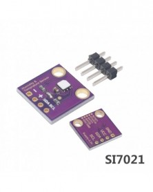
Szín: SHT20 - 1 db DC1080 Si7021 SHT20 ipari nagy pontosságú páratartalom érzékelő I2C interfésszel GY-213V-SI7021
262 Ft 476 FtDescritipion:
The main chip is GY-213V-HDC1080(Can use SHT21 HTU21D SI7021 chip to made the same sensor)
This I2C digital humidity sensor is a fairly accurate and intelligent alternative to the much simpler Humidity and Temperature Sensor - SHT15 Breakout It has a typical accuracy of ±4% with an operating range that's optimized from 10% to 80% RH. Operation outside this range is still possible - just the accuracy might drop a bit. The temperature output has a typical accuracy of ±0.2°C from -20~85°C.
The HDC1080 sensor chip has 2 address-select pins, so you can have up to 4 shared on a single I2C bus. It's also 3-5V power and logic safe so you don't need any level shifters or regulators to use with a 5V or 3V microcontroller.
Please note: TI has indicated that there's a 'settling' effect for the humidity and that you will need to re-hydrate the sensor once you receive it. To rehydrate it, place it in a location with 85% humidity for 24 hours or 60% humidity for 10 days.
The HDC1080 is a digital humidity sensor with integrated temperature sensor that provides excellent measurement accuracy at very low power. The HDC1080 operates over a wide supply range, and is a low cost, low power alternative to competitive solutions in a wide range of common applications. The humidity and temperature sensors are factory calibrated.
Features:
Relative Humidity Accuracy ±2% (typical)
Temperature Accuracy ±0.2°C (typical)
Excellent Stability at High Humidity
14 Bit Measurement Resolution
100 nA Sleep Mode Current
Power Pins:
Vin - this is the power pin. Unlike many sensors, this chip can be powered by 3-5 VDC, so there is no voltage regulator on board. Simply power the board with the same power as the logic level of your microcontroller - e.g. for a 5V micro like Arduino, use 5V. For a 3V ARM processor, use 3V
GND - common ground for power and logic
I2C Logic pins:
SCL - I2C clock pin, connect to your microcontrollers I2C clock line. 3-5V logic OK
SDA - I2C data pin, connect to your microcontrollers I2C data line. 3-5V logic OK
Optional Pins:
These are pins you don't need to connect to unless you want to!
RDY - This is the interrupt/'ready' pin from the HDC100x. The chip has some capability to 'alert' you when data is ready to be read from the sensor. We don't use this pin in our library but it's available if you need it! It is open collector so you need to use a pull-up resistor if you want to read signal from this pin.
A0 A1 - These are the address select pins. Since you can only have one device with a given address on an i2c bus, there must be a way to adjust the address if you want to put more than one HDC100X on a shared i2c bus. The A0/A1 pins set the bottom 2 bits of the i2c address. There are pull-down resistors on the board so connect them to Vin to set the bits to '1'. They are read on power up, so de-power and re-power to reset the address
Si7021 humidity and temperature sensor
Description:
The main chip of this item is GY-213V-HTU21D
The HTU21D is a low-cost, easy to use, highly accurate, digital humidity and temperature sensor.
This sensor is ideal for environmental sensing and data logging and perfect for a weather stations or humidor control systems. All you need is two lines for I2C communication and you'll have relative humidity readings and very accurate temperature readings as a bonus!
There are only four pins that need to be hooked up in order to startusing this sensor in a project.
One for VCC, one for GND, and two data lines for I2C communication. This breakout board has built in 4.7k pull up resistors for I2C communications.If you're hooking up multiple I2C devices on the same bus, you may want to disable these resistors.Dimensions: 0.6 x 0.6"
SHT20 Temperature Humidity Sensor Module
Technical Parameters:
Supply voltage: 1.5V-3.6V
Humidity measuring range: 0-100% RH
Temperature range: -40 °-105°
Maximum power consumption: 2.7uW
Communication: I2C
Humidity accuracy range:10% RH to 95% RH
Humidity Hysteresis: ±1% RH
Measurement time: 50ms
The annual shift: -0.5% RH / year
10. Response time: 5s
HTU20D T: /-0.3°
RH: /- 4% RH
HTU21D T: /-0.3°
RH: /- 2% RH
Storage temperature: -40° ~ 125°
Working humidity range: 0-100% RH
Working temperature range: -40° ~ 105° -
Szín: HDC1080 - 1 db DC1080 Si7021 SHT20 ipari nagy pontosságú páratartalom érzékelő I2C interfésszel GY-213V-SI7021
208 Ft 378 FtDescritipion:
The main chip is GY-213V-HDC1080(Can use SHT21 HTU21D SI7021 chip to made the same sensor)
This I2C digital humidity sensor is a fairly accurate and intelligent alternative to the much simpler Humidity and Temperature Sensor - SHT15 Breakout It has a typical accuracy of ±4% with an operating range that's optimized from 10% to 80% RH. Operation outside this range is still possible - just the accuracy might drop a bit. The temperature output has a typical accuracy of ±0.2°C from -20~85°C.
The HDC1080 sensor chip has 2 address-select pins, so you can have up to 4 shared on a single I2C bus. It's also 3-5V power and logic safe so you don't need any level shifters or regulators to use with a 5V or 3V microcontroller.
Please note: TI has indicated that there's a 'settling' effect for the humidity and that you will need to re-hydrate the sensor once you receive it. To rehydrate it, place it in a location with 85% humidity for 24 hours or 60% humidity for 10 days.
The HDC1080 is a digital humidity sensor with integrated temperature sensor that provides excellent measurement accuracy at very low power. The HDC1080 operates over a wide supply range, and is a low cost, low power alternative to competitive solutions in a wide range of common applications. The humidity and temperature sensors are factory calibrated.
Features:
Relative Humidity Accuracy ±2% (typical)
Temperature Accuracy ±0.2°C (typical)
Excellent Stability at High Humidity
14 Bit Measurement Resolution
100 nA Sleep Mode Current
Power Pins:
Vin - this is the power pin. Unlike many sensors, this chip can be powered by 3-5 VDC, so there is no voltage regulator on board. Simply power the board with the same power as the logic level of your microcontroller - e.g. for a 5V micro like Arduino, use 5V. For a 3V ARM processor, use 3V
GND - common ground for power and logic
I2C Logic pins:
SCL - I2C clock pin, connect to your microcontrollers I2C clock line. 3-5V logic OK
SDA - I2C data pin, connect to your microcontrollers I2C data line. 3-5V logic OK
Optional Pins:
These are pins you don't need to connect to unless you want to!
RDY - This is the interrupt/'ready' pin from the HDC100x. The chip has some capability to 'alert' you when data is ready to be read from the sensor. We don't use this pin in our library but it's available if you need it! It is open collector so you need to use a pull-up resistor if you want to read signal from this pin.
A0 A1 - These are the address select pins. Since you can only have one device with a given address on an i2c bus, there must be a way to adjust the address if you want to put more than one HDC100X on a shared i2c bus. The A0/A1 pins set the bottom 2 bits of the i2c address. There are pull-down resistors on the board so connect them to Vin to set the bits to '1'. They are read on power up, so de-power and re-power to reset the address
Si7021 humidity and temperature sensor
Description:
The main chip of this item is GY-213V-HTU21D
The HTU21D is a low-cost, easy to use, highly accurate, digital humidity and temperature sensor.
This sensor is ideal for environmental sensing and data logging and perfect for a weather stations or humidor control systems. All you need is two lines for I2C communication and you'll have relative humidity readings and very accurate temperature readings as a bonus!
There are only four pins that need to be hooked up in order to startusing this sensor in a project.
One for VCC, one for GND, and two data lines for I2C communication. This breakout board has built in 4.7k pull up resistors for I2C communications.If you're hooking up multiple I2C devices on the same bus, you may want to disable these resistors.Dimensions: 0.6 x 0.6"
SHT20 Temperature Humidity Sensor Module
Technical Parameters:
Supply voltage: 1.5V-3.6V
Humidity measuring range: 0-100% RH
Temperature range: -40 °-105°
Maximum power consumption: 2.7uW
Communication: I2C
Humidity accuracy range:10% RH to 95% RH
Humidity Hysteresis: ±1% RH
Measurement time: 50ms
The annual shift: -0.5% RH / year
10. Response time: 5s
HTU20D T: /-0.3°
RH: /- 4% RH
HTU21D T: /-0.3°
RH: /- 2% RH
Storage temperature: -40° ~ 125°
Working humidity range: 0-100% RH
Working temperature range: -40° ~ 105° -
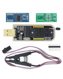
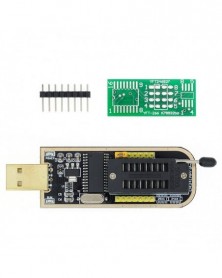
Szín: SOIC8 SOP8 teszt klip - I21 CH341A 24 25 sorozatú EEPROM Flash BIOS USB programozó modul SOIC8 SOP8 tesztcsipesz
215 Ft 391 FtDriver download address: http://drive.google.com/open?id=1us2XLkDSgD_9jPmDEjGY1nvqdUSqTszg
USB Programmer
Condition: New
Support 24EEPROM and 25 SPI flash 8pin/16pin chip
USB to TTL port, can getroot online
With CH341A chip
Recognize 25 series chip automatically
And support download STC series procedure of singlechip
With 24/25 status indicator lamp
SPI pin to support expanding the utility
Color is shown as pictures
PLS NOTE that due to lighting effects, monitor's brightness/ contrass settings ect, there could be some slight differences in the color tone of the pictures and the actual item!
Provide 5V-3.3V power supply output
Dimension:70mm x 27mm -
Szín: 1 szett - I21 CH341A 24 25 sorozatú EEPROM Flash BIOS USB programozó modul SOIC8 SOP8 tesztcsipesz EEPROM 93CXX
401 Ft 729 FtDriver download address: http://drive.google.com/open?id=1us2XLkDSgD_9jPmDEjGY1nvqdUSqTszg
USB Programmer
Condition: New
Support 24EEPROM and 25 SPI flash 8pin/16pin chip
USB to TTL port, can getroot online
With CH341A chip
Recognize 25 series chip automatically
And support download STC series procedure of singlechip
With 24/25 status indicator lamp
SPI pin to support expanding the utility
Color is shown as pictures
PLS NOTE that due to lighting effects, monitor's brightness/ contrass settings ect, there could be some slight differences in the color tone of the pictures and the actual item!
Provide 5V-3.3V power supply output
Dimension:70mm x 27mm -
Szín: CH341A - I21 CH341A 24 25 sorozatú EEPROM Flash BIOS USB programozó modul SOIC8 SOP8 tesztcsipesz EEPROM 93CXX
270 Ft 491 FtDriver download address: http://drive.google.com/open?id=1us2XLkDSgD_9jPmDEjGY1nvqdUSqTszg
USB Programmer
Condition: New
Support 24EEPROM and 25 SPI flash 8pin/16pin chip
USB to TTL port, can getroot online
With CH341A chip
Recognize 25 series chip automatically
And support download STC series procedure of singlechip
With 24/25 status indicator lamp
SPI pin to support expanding the utility
Color is shown as pictures
PLS NOTE that due to lighting effects, monitor's brightness/ contrass settings ect, there could be some slight differences in the color tone of the pictures and the actual item!
Provide 5V-3.3V power supply output
Dimension:70mm x 27mm -
Szín: SOIC8 SOP8 teszt klip - I21 CH341A 24 25 sorozatú EEPROM Flash BIOS USB programozó modul SOIC8 SOP8 tesztcsipesz
205 Ft 373 FtDriver download address: http://drive.google.com/open?id=1us2XLkDSgD_9jPmDEjGY1nvqdUSqTszg
USB Programmer
Condition: New
Support 24EEPROM and 25 SPI flash 8pin/16pin chip
USB to TTL port, can getroot online
With CH341A chip
Recognize 25 series chip automatically
And support download STC series procedure of singlechip
With 24/25 status indicator lamp
SPI pin to support expanding the utility
Color is shown as pictures
PLS NOTE that due to lighting effects, monitor's brightness/ contrass settings ect, there could be some slight differences in the color tone of the pictures and the actual item!
Provide 5V-3.3V power supply output
Dimension:70mm x 27mm -
Szín: 1 szett - I21 CH341A 24 25 sorozatú EEPROM Flash BIOS USB programozó modul SOIC8 SOP8 tesztcsipesz EEPROM 93CXX
391 Ft 710 FtDriver download address: http://drive.google.com/open?id=1us2XLkDSgD_9jPmDEjGY1nvqdUSqTszg
USB Programmer
Condition: New
Support 24EEPROM and 25 SPI flash 8pin/16pin chip
USB to TTL port, can getroot online
With CH341A chip
Recognize 25 series chip automatically
And support download STC series procedure of singlechip
With 24/25 status indicator lamp
SPI pin to support expanding the utility
Color is shown as pictures
PLS NOTE that due to lighting effects, monitor's brightness/ contrass settings ect, there could be some slight differences in the color tone of the pictures and the actual item!
Provide 5V-3.3V power supply output
Dimension:70mm x 27mm -
Szín: CH341A - I21 CH341A 24 25 sorozatú EEPROM Flash BIOS USB programozó modul SOIC8 SOP8 tesztcsipesz EEPROM 93CXX
260 Ft 473 FtDriver download address: http://drive.google.com/open?id=1us2XLkDSgD_9jPmDEjGY1nvqdUSqTszg
USB Programmer
Condition: New
Support 24EEPROM and 25 SPI flash 8pin/16pin chip
USB to TTL port, can getroot online
With CH341A chip
Recognize 25 series chip automatically
And support download STC series procedure of singlechip
With 24/25 status indicator lamp
SPI pin to support expanding the utility
Color is shown as pictures
PLS NOTE that due to lighting effects, monitor's brightness/ contrass settings ect, there could be some slight differences in the color tone of the pictures and the actual item!
Provide 5V-3.3V power supply output
Dimension:70mm x 27mm -
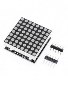
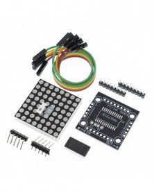
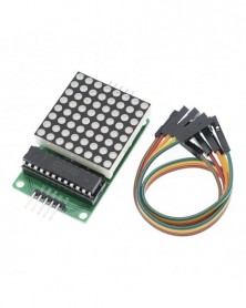
Szín: MAX7219 SMD - MAX7219 pontmátrix modul mikrokontroller kijelző modul MCU LED kijelző vezérlő modul Arduino 5V DIY
188 Ft 342 FtMAX7219 DIY Kits
1 single module can drive the an 8 * 8 dot matrix common cathode
2 the module Operating voltage: 5 v
The Module 3 dimensions: length 3.2 cm X 3.2 cm wide X 1.3 cm high
4 holes with four screws, the diameter of 3 mm
Five modules with input and output interfaces, support for cascading multiple modules
Wiring instructions:
1 on the left block to an input port, the an output port on the right.
2 the When the control of a single module, simple enter the port received a CPU
The When wining 3 modules cascaded output input termination CPU, the input output termination module of the first two modules of the first one, the first two modules of the termination input terminal of the three modules, and so.
The To 51 single example:
VCC 5 v
GND GND
DIN P2.2
CS P2.1
CLK P2.0
MAX7219 4 IN 1 Module
A single module can drive a 8x8 dot matrix common cathode
Operating Voltage: 5V
A single module can drive a 8x8 dot matrix common cathode
Operating Voltage: 5V
Dimensions: 12.8X12.8X1.3cm/
Fixing screws with 64 holes with a diameter 3mm
Module with input and output interfaces, support for cascading multiple modules
Quality:1Set
The left side of the module to the input port, the right to an output port
When the control of a single module, simply input port connected to CPU
When a plurality of cascaded modules, input and output termination CPU, an input terminal of the second output end of the first module a module, the first two modules of the input terminal of the three termination modules, and so on...
51 microcontrollers, for example:
VCC 5V
GND GND
DIN P2.2
CS P2.1
CLK P2.0
MAX7219 Digital Display Control Module
MAX7219 is an integrated serial input / output common-cathode display driver, which connects the microprocessor 7-segment digital LED display with 8 digits, you can connect a bar graph display or 64 independent LED. On which includes a B-type BCD encoder chip, multi-channel scanning loop, segment word driver, but also an 8 x 8 static RAM for storing each data. Only one external register is used to set the segment current for each LED.
A convenient four-wire serial interface can connect all the general-purpose microprocessor. Each data can be addressed in the update does not need to rewrite all of the display. MAX7219 also allows users to select each data coding or non-coding.
The entire device contains a 150μA low-power shutdown mode, analog and digital brightness control, a scan-limit register allows the user to display 1-8 bit data, there is a LED light all the detection mode.
Only three IO ports to drive eight digital tube! Digital flicker-free display! Support cascade!
PCB plate fixed to the four corners of copper studs, which can effectively prevent a short circuit accident occurs!
Digital tube 0.36 inches four one common cathode LED
This module is compatible with 5V / 3.3V microcontroller (51 / AVR / STM32 .......)
Wiring instructions (in program provides an example, you can access any IO ports, you can modify the port defined in the program):
VCC → 5V
GND → GND
DIN → P00
CS → P01
CLK → P02
NOTES:
1.VCC and GND Do not reversed, it would burn chip
2.51 MCU P0 port need pull-up resistor, if your device does not have pull-up resistor can be connected to other ports data lines
Invoice:
1.MAX7219 digital display module 1
2. Straight pin 5P
3. bent pin 5P
-
Szín: MAX7219 DIY KIT - MAX7219 pontmátrix modul mikrokontroller kijelző modul MCU LED kijelző vezérlő modul Arduino 5V
179 Ft 326 FtMAX7219 DIY Kits
1 single module can drive the an 8 * 8 dot matrix common cathode
2 the module Operating voltage: 5 v
The Module 3 dimensions: length 3.2 cm X 3.2 cm wide X 1.3 cm high
4 holes with four screws, the diameter of 3 mm
Five modules with input and output interfaces, support for cascading multiple modules
Wiring instructions:
1 on the left block to an input port, the an output port on the right.
2 the When the control of a single module, simple enter the port received a CPU
The When wining 3 modules cascaded output input termination CPU, the input output termination module of the first two modules of the first one, the first two modules of the termination input terminal of the three modules, and so.
The To 51 single example:
VCC 5 v
GND GND
DIN P2.2
CS P2.1
CLK P2.0
MAX7219 4 IN 1 Module
A single module can drive a 8x8 dot matrix common cathode
Operating Voltage: 5V
A single module can drive a 8x8 dot matrix common cathode
Operating Voltage: 5V
Dimensions: 12.8X12.8X1.3cm/
Fixing screws with 64 holes with a diameter 3mm
Module with input and output interfaces, support for cascading multiple modules
Quality:1Set
The left side of the module to the input port, the right to an output port
When the control of a single module, simply input port connected to CPU
When a plurality of cascaded modules, input and output termination CPU, an input terminal of the second output end of the first module a module, the first two modules of the input terminal of the three termination modules, and so on...
51 microcontrollers, for example:
VCC 5V
GND GND
DIN P2.2
CS P2.1
CLK P2.0
MAX7219 Digital Display Control Module
MAX7219 is an integrated serial input / output common-cathode display driver, which connects the microprocessor 7-segment digital LED display with 8 digits, you can connect a bar graph display or 64 independent LED. On which includes a B-type BCD encoder chip, multi-channel scanning loop, segment word driver, but also an 8 x 8 static RAM for storing each data. Only one external register is used to set the segment current for each LED.
A convenient four-wire serial interface can connect all the general-purpose microprocessor. Each data can be addressed in the update does not need to rewrite all of the display. MAX7219 also allows users to select each data coding or non-coding.
The entire device contains a 150μA low-power shutdown mode, analog and digital brightness control, a scan-limit register allows the user to display 1-8 bit data, there is a LED light all the detection mode.
Only three IO ports to drive eight digital tube! Digital flicker-free display! Support cascade!
PCB plate fixed to the four corners of copper studs, which can effectively prevent a short circuit accident occurs!
Digital tube 0.36 inches four one common cathode LED
This module is compatible with 5V / 3.3V microcontroller (51 / AVR / STM32 .......)
Wiring instructions (in program provides an example, you can access any IO ports, you can modify the port defined in the program):
VCC → 5V
GND → GND
DIN → P00
CS → P01
CLK → P02
NOTES:
1.VCC and GND Do not reversed, it would burn chip
2.51 MCU P0 port need pull-up resistor, if your device does not have pull-up resistor can be connected to other ports data lines
Invoice:
1.MAX7219 digital display module 1
2. Straight pin 5P
3. bent pin 5P
-
Szín: MAX7219 DIP - MAX7219 pontmátrix modul mikrokontroller kijelző modul MCU LED kijelző vezérlő modul Arduino 5V DIY
279 Ft 507 FtMAX7219 DIY Kits
1 single module can drive the an 8 * 8 dot matrix common cathode
2 the module Operating voltage: 5 v
The Module 3 dimensions: length 3.2 cm X 3.2 cm wide X 1.3 cm high
4 holes with four screws, the diameter of 3 mm
Five modules with input and output interfaces, support for cascading multiple modules
Wiring instructions:
1 on the left block to an input port, the an output port on the right.
2 the When the control of a single module, simple enter the port received a CPU
The When wining 3 modules cascaded output input termination CPU, the input output termination module of the first two modules of the first one, the first two modules of the termination input terminal of the three modules, and so.
The To 51 single example:
VCC 5 v
GND GND
DIN P2.2
CS P2.1
CLK P2.0
MAX7219 4 IN 1 Module
A single module can drive a 8x8 dot matrix common cathode
Operating Voltage: 5V
A single module can drive a 8x8 dot matrix common cathode
Operating Voltage: 5V
Dimensions: 12.8X12.8X1.3cm/
Fixing screws with 64 holes with a diameter 3mm
Module with input and output interfaces, support for cascading multiple modules
Quality:1Set
The left side of the module to the input port, the right to an output port
When the control of a single module, simply input port connected to CPU
When a plurality of cascaded modules, input and output termination CPU, an input terminal of the second output end of the first module a module, the first two modules of the input terminal of the three termination modules, and so on...
51 microcontrollers, for example:
VCC 5V
GND GND
DIN P2.2
CS P2.1
CLK P2.0
MAX7219 Digital Display Control Module
MAX7219 is an integrated serial input / output common-cathode display driver, which connects the microprocessor 7-segment digital LED display with 8 digits, you can connect a bar graph display or 64 independent LED. On which includes a B-type BCD encoder chip, multi-channel scanning loop, segment word driver, but also an 8 x 8 static RAM for storing each data. Only one external register is used to set the segment current for each LED.
A convenient four-wire serial interface can connect all the general-purpose microprocessor. Each data can be addressed in the update does not need to rewrite all of the display. MAX7219 also allows users to select each data coding or non-coding.
The entire device contains a 150μA low-power shutdown mode, analog and digital brightness control, a scan-limit register allows the user to display 1-8 bit data, there is a LED light all the detection mode.
Only three IO ports to drive eight digital tube! Digital flicker-free display! Support cascade!
PCB plate fixed to the four corners of copper studs, which can effectively prevent a short circuit accident occurs!
Digital tube 0.36 inches four one common cathode LED
This module is compatible with 5V / 3.3V microcontroller (51 / AVR / STM32 .......)
Wiring instructions (in program provides an example, you can access any IO ports, you can modify the port defined in the program):
VCC → 5V
GND → GND
DIN → P00
CS → P01
CLK → P02
NOTES:
1.VCC and GND Do not reversed, it would burn chip
2.51 MCU P0 port need pull-up resistor, if your device does not have pull-up resistor can be connected to other ports data lines
Invoice:
1.MAX7219 digital display module 1
2. Straight pin 5P
3. bent pin 5P
-
Szín: 4 IN 1 - Piros LED - MAX7219 pontmátrix modul mikrokontroller kijelző modul MCU LED kijelző vezérlő modul Arduino 5V
392 Ft 713 FtMAX7219 DIY Kits
1 single module can drive the an 8 * 8 dot matrix common cathode
2 the module Operating voltage: 5 v
The Module 3 dimensions: length 3.2 cm X 3.2 cm wide X 1.3 cm high
4 holes with four screws, the diameter of 3 mm
Five modules with input and output interfaces, support for cascading multiple modules
Wiring instructions:
1 on the left block to an input port, the an output port on the right.
2 the When the control of a single module, simple enter the port received a CPU
The When wining 3 modules cascaded output input termination CPU, the input output termination module of the first two modules of the first one, the first two modules of the termination input terminal of the three modules, and so.
The To 51 single example:
VCC 5 v
GND GND
DIN P2.2
CS P2.1
CLK P2.0
MAX7219 4 IN 1 Module
A single module can drive a 8x8 dot matrix common cathode
Operating Voltage: 5V
A single module can drive a 8x8 dot matrix common cathode
Operating Voltage: 5V
Dimensions: 12.8X12.8X1.3cm/
Fixing screws with 64 holes with a diameter 3mm
Module with input and output interfaces, support for cascading multiple modules
Quality:1Set
The left side of the module to the input port, the right to an output port
When the control of a single module, simply input port connected to CPU
When a plurality of cascaded modules, input and output termination CPU, an input terminal of the second output end of the first module a module, the first two modules of the input terminal of the three termination modules, and so on...
51 microcontrollers, for example:
VCC 5V
GND GND
DIN P2.2
CS P2.1
CLK P2.0
MAX7219 Digital Display Control Module
MAX7219 is an integrated serial input / output common-cathode display driver, which connects the microprocessor 7-segment digital LED display with 8 digits, you can connect a bar graph display or 64 independent LED. On which includes a B-type BCD encoder chip, multi-channel scanning loop, segment word driver, but also an 8 x 8 static RAM for storing each data. Only one external register is used to set the segment current for each LED.
A convenient four-wire serial interface can connect all the general-purpose microprocessor. Each data can be addressed in the update does not need to rewrite all of the display. MAX7219 also allows users to select each data coding or non-coding.
The entire device contains a 150μA low-power shutdown mode, analog and digital brightness control, a scan-limit register allows the user to display 1-8 bit data, there is a LED light all the detection mode.
Only three IO ports to drive eight digital tube! Digital flicker-free display! Support cascade!
PCB plate fixed to the four corners of copper studs, which can effectively prevent a short circuit accident occurs!
Digital tube 0.36 inches four one common cathode LED
This module is compatible with 5V / 3.3V microcontroller (51 / AVR / STM32 .......)
Wiring instructions (in program provides an example, you can access any IO ports, you can modify the port defined in the program):
VCC → 5V
GND → GND
DIN → P00
CS → P01
CLK → P02
NOTES:
1.VCC and GND Do not reversed, it would burn chip
2.51 MCU P0 port need pull-up resistor, if your device does not have pull-up resistor can be connected to other ports data lines
Invoice:
1.MAX7219 digital display module 1
2. Straight pin 5P
3. bent pin 5P
-
Szín: 4 IN 1 - Kék LED - MAX7219 pontmátrix modul mikrokontroller kijelző modul MCU LED kijelző vezérlő modul Arduino 5V
485 Ft 882 FtMAX7219 DIY Kits
1 single module can drive the an 8 * 8 dot matrix common cathode
2 the module Operating voltage: 5 v
The Module 3 dimensions: length 3.2 cm X 3.2 cm wide X 1.3 cm high
4 holes with four screws, the diameter of 3 mm
Five modules with input and output interfaces, support for cascading multiple modules
Wiring instructions:
1 on the left block to an input port, the an output port on the right.
2 the When the control of a single module, simple enter the port received a CPU
The When wining 3 modules cascaded output input termination CPU, the input output termination module of the first two modules of the first one, the first two modules of the termination input terminal of the three modules, and so.
The To 51 single example:
VCC 5 v
GND GND
DIN P2.2
CS P2.1
CLK P2.0
MAX7219 4 IN 1 Module
A single module can drive a 8x8 dot matrix common cathode
Operating Voltage: 5V
A single module can drive a 8x8 dot matrix common cathode
Operating Voltage: 5V
Dimensions: 12.8X12.8X1.3cm/
Fixing screws with 64 holes with a diameter 3mm
Module with input and output interfaces, support for cascading multiple modules
Quality:1Set
The left side of the module to the input port, the right to an output port
When the control of a single module, simply input port connected to CPU
When a plurality of cascaded modules, input and output termination CPU, an input terminal of the second output end of the first module a module, the first two modules of the input terminal of the three termination modules, and so on...
51 microcontrollers, for example:
VCC 5V
GND GND
DIN P2.2
CS P2.1
CLK P2.0
MAX7219 Digital Display Control Module
MAX7219 is an integrated serial input / output common-cathode display driver, which connects the microprocessor 7-segment digital LED display with 8 digits, you can connect a bar graph display or 64 independent LED. On which includes a B-type BCD encoder chip, multi-channel scanning loop, segment word driver, but also an 8 x 8 static RAM for storing each data. Only one external register is used to set the segment current for each LED.
A convenient four-wire serial interface can connect all the general-purpose microprocessor. Each data can be addressed in the update does not need to rewrite all of the display. MAX7219 also allows users to select each data coding or non-coding.
The entire device contains a 150μA low-power shutdown mode, analog and digital brightness control, a scan-limit register allows the user to display 1-8 bit data, there is a LED light all the detection mode.
Only three IO ports to drive eight digital tube! Digital flicker-free display! Support cascade!
PCB plate fixed to the four corners of copper studs, which can effectively prevent a short circuit accident occurs!
Digital tube 0.36 inches four one common cathode LED
This module is compatible with 5V / 3.3V microcontroller (51 / AVR / STM32 .......)
Wiring instructions (in program provides an example, you can access any IO ports, you can modify the port defined in the program):
VCC → 5V
GND → GND
DIN → P00
CS → P01
CLK → P02
NOTES:
1.VCC and GND Do not reversed, it would burn chip
2.51 MCU P0 port need pull-up resistor, if your device does not have pull-up resistor can be connected to other ports data lines
Invoice:
1.MAX7219 digital display module 1
2. Straight pin 5P
3. bent pin 5P
-
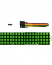
Szín: 4 IN 1 - Zöld LED - MAX7219 pontmátrix modul mikrokontroller kijelző modul MCU LED kijelző vezérlő modul Arduino 5V
445 Ft 809 FtMAX7219 DIY Kits
1 single module can drive the an 8 * 8 dot matrix common cathode
2 the module Operating voltage: 5 v
The Module 3 dimensions: length 3.2 cm X 3.2 cm wide X 1.3 cm high
4 holes with four screws, the diameter of 3 mm
Five modules with input and output interfaces, support for cascading multiple modules
Wiring instructions:
1 on the left block to an input port, the an output port on the right.
2 the When the control of a single module, simple enter the port received a CPU
The When wining 3 modules cascaded output input termination CPU, the input output termination module of the first two modules of the first one, the first two modules of the termination input terminal of the three modules, and so.
The To 51 single example:
VCC 5 v
GND GND
DIN P2.2
CS P2.1
CLK P2.0
MAX7219 4 IN 1 Module
A single module can drive a 8x8 dot matrix common cathode
Operating Voltage: 5V
A single module can drive a 8x8 dot matrix common cathode
Operating Voltage: 5V
Dimensions: 12.8X12.8X1.3cm/
Fixing screws with 64 holes with a diameter 3mm
Module with input and output interfaces, support for cascading multiple modules
Quality:1Set
The left side of the module to the input port, the right to an output port
When the control of a single module, simply input port connected to CPU
When a plurality of cascaded modules, input and output termination CPU, an input terminal of the second output end of the first module a module, the first two modules of the input terminal of the three termination modules, and so on...
51 microcontrollers, for example:
VCC 5V
GND GND
DIN P2.2
CS P2.1
CLK P2.0
MAX7219 Digital Display Control Module
MAX7219 is an integrated serial input / output common-cathode display driver, which connects the microprocessor 7-segment digital LED display with 8 digits, you can connect a bar graph display or 64 independent LED. On which includes a B-type BCD encoder chip, multi-channel scanning loop, segment word driver, but also an 8 x 8 static RAM for storing each data. Only one external register is used to set the segment current for each LED.
A convenient four-wire serial interface can connect all the general-purpose microprocessor. Each data can be addressed in the update does not need to rewrite all of the display. MAX7219 also allows users to select each data coding or non-coding.
The entire device contains a 150μA low-power shutdown mode, analog and digital brightness control, a scan-limit register allows the user to display 1-8 bit data, there is a LED light all the detection mode.
Only three IO ports to drive eight digital tube! Digital flicker-free display! Support cascade!
PCB plate fixed to the four corners of copper studs, which can effectively prevent a short circuit accident occurs!
Digital tube 0.36 inches four one common cathode LED
This module is compatible with 5V / 3.3V microcontroller (51 / AVR / STM32 .......)
Wiring instructions (in program provides an example, you can access any IO ports, you can modify the port defined in the program):
VCC → 5V
GND → GND
DIN → P00
CS → P01
CLK → P02
NOTES:
1.VCC and GND Do not reversed, it would burn chip
2.51 MCU P0 port need pull-up resistor, if your device does not have pull-up resistor can be connected to other ports data lines
Invoice:
1.MAX7219 digital display module 1
2. Straight pin 5P
3. bent pin 5P
-
Szín: 8 számjegyű piros LED - MAX7219 pontmátrix modul mikrokontroller kijelző modul MCU LED kijelző vezérlő modul
190 Ft 346 FtMAX7219 DIY Kits
1 single module can drive the an 8 * 8 dot matrix common cathode
2 the module Operating voltage: 5 v
The Module 3 dimensions: length 3.2 cm X 3.2 cm wide X 1.3 cm high
4 holes with four screws, the diameter of 3 mm
Five modules with input and output interfaces, support for cascading multiple modules
Wiring instructions:
1 on the left block to an input port, the an output port on the right.
2 the When the control of a single module, simple enter the port received a CPU
The When wining 3 modules cascaded output input termination CPU, the input output termination module of the first two modules of the first one, the first two modules of the termination input terminal of the three modules, and so.
The To 51 single example:
VCC 5 v
GND GND
DIN P2.2
CS P2.1
CLK P2.0
MAX7219 4 IN 1 Module
A single module can drive a 8x8 dot matrix common cathode
Operating Voltage: 5V
A single module can drive a 8x8 dot matrix common cathode
Operating Voltage: 5V
Dimensions: 12.8X12.8X1.3cm/
Fixing screws with 64 holes with a diameter 3mm
Module with input and output interfaces, support for cascading multiple modules
Quality:1Set
The left side of the module to the input port, the right to an output port
When the control of a single module, simply input port connected to CPU
When a plurality of cascaded modules, input and output termination CPU, an input terminal of the second output end of the first module a module, the first two modules of the input terminal of the three termination modules, and so on...
51 microcontrollers, for example:
VCC 5V
GND GND
DIN P2.2
CS P2.1
CLK P2.0
MAX7219 Digital Display Control Module
MAX7219 is an integrated serial input / output common-cathode display driver, which connects the microprocessor 7-segment digital LED display with 8 digits, you can connect a bar graph display or 64 independent LED. On which includes a B-type BCD encoder chip, multi-channel scanning loop, segment word driver, but also an 8 x 8 static RAM for storing each data. Only one external register is used to set the segment current for each LED.
A convenient four-wire serial interface can connect all the general-purpose microprocessor. Each data can be addressed in the update does not need to rewrite all of the display. MAX7219 also allows users to select each data coding or non-coding.
The entire device contains a 150μA low-power shutdown mode, analog and digital brightness control, a scan-limit register allows the user to display 1-8 bit data, there is a LED light all the detection mode.
Only three IO ports to drive eight digital tube! Digital flicker-free display! Support cascade!
PCB plate fixed to the four corners of copper studs, which can effectively prevent a short circuit accident occurs!
Digital tube 0.36 inches four one common cathode LED
This module is compatible with 5V / 3.3V microcontroller (51 / AVR / STM32 .......)
Wiring instructions (in program provides an example, you can access any IO ports, you can modify the port defined in the program):
VCC → 5V
GND → GND
DIN → P00
CS → P01
CLK → P02
NOTES:
1.VCC and GND Do not reversed, it would burn chip
2.51 MCU P0 port need pull-up resistor, if your device does not have pull-up resistor can be connected to other ports data lines
Invoice:
1.MAX7219 digital display module 1
2. Straight pin 5P
3. bent pin 5P
-
Szín: PLATÓ-170 - 170 Wishful Clamp Barkácsfogó Elektronikus fogó Átlós fogó Wishful Clamp
235 Ft 428 FtFeatures:
100% quality and Brand new.
Spring loaded for easy use
Automatic rebound function
45degangle use in tight spaces
Carbon steel hardening treatment
Light weight, thin profile and easy handling insulate grips comfortable for operation
Feel comfortable and convenient to use
Special suitable for cut wire, electronic feet, trimming plastic products, cut a small metal wire, and so on Used in electronic industry repair, jewelry processing, model making and fishing, etc
Specification:
Color: Blue
Material: Stainless steel jaw, Anti-slip rubber handle
Length: 12mm
Packing list :
1x Cable cutter (no retail box) -
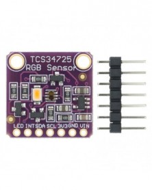
1 db CJMCU-34725 TCS34725 színérzékelő RGB színérzékelő fejlesztőkártya, 34725 modul
312 Ft 568 Ft1. Red, Green, Blue (RGB), and White Light Sensing with IR Blocking Filter
2. Programmable Analog Gain and Integration Time
3. 3,800,000:1 Dynamic Range
4. Very High Sensitivity ? Ideally Suited for Operation Behind Dark Glass
5. Maskable Interrupt
6. Programmable Upper and Lower Thresholds with Persistence Filter
7. Power Management
8. Low Power ? 2.5-uA Sleep State
9. 65-uA Wait State with Programmable Wait State Time from 2.4 ms to > 7 Seconds
10. I2C Fast Mode Compatible Interface
11. Data Rates up to 400 kbit/s
12. Input Voltage Levels Compatible with VDD or 1.8 V Bus
13. Register Set and Pin Compatible with the TCS3x71 Series
14. Small 2 mm*2.4 mm Dual Flat No-Lead (FN)
Applications
1. RGB LED Backlight Control
2. Light Color Temperature Measurement
3. Ambient Light Sensing for Display Backlight Control
4. Fluid and Gas Analysis
5. Product Color Verification and Sorting -
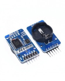
1 db DS3231 AT24C32 IIC modul Precíziós óramodul (akkumulátor nélkül) DS3231SN Memóriamodul C75
255 Ft 464 FtDS3231 is a low-cost, extremely accurate I2C real-time clock (RTC), with an integrated temperature-compensated crystal oscillator (TCXO) and crystal. The device incorporates a battery input, disconnect the main power supply and maintains accurate timekeeping. Integrated oscillator improve long-term accuracy of the device and reduces the number of components of the production line. The DS3231 is available in commercial and industrial temperature ranges, using a 16-pin 300mil SO package.
RTC maintains seconds, minutes, hours, day, date, month, and year information. Less than 31 days of the month, the end date will be automatically adjusted, including corrections for leap year. The clock operates in either the 24 hours or band / AM / PM indication of the 12-hour format. Provides two configurable alarm clock and a calendar can be set to a square wave output. Address and data are transferred serially through an I2C bidirectional bus.
A precision temperature-compensated voltage reference and comparator circuit monitors the status of VCC to detect power failures, provide a reset output, and if necessary, automatically switch to the backup power supply. In addition, / RST pin is monitored as generating μP reset manually.
Save time and high precision addition, DS3231 also has some other features that extend the system host of additional features and a range of options. The device integrates a very precise digital temperature sensor, through the I2C * interface to access it (as the same time). This temperature sensor accuracy is ± 3 ° C. On-chip power supply control circuit can automatically detect and manage the main and standby power (i.e., low-voltage battery) to switch between the power supply. If the main power failure, the device can continue to provide accurate timing and temperature, performance is not affected. When the main power re-power or voltage value returns to within the allowable range, the on-chip reset function can be used to restart the system microprocessor.
Module parameters:
1 Size: 38mm (length) * 22mm (W) * 14mm (height)
2 Weight: 8g
3 Operating voltage :3.3 - 5 .5 V
4 clock chip: high-precision clock chip DS3231
5 Clock Accuracy :0-40 ° range, the accuracy 2ppm, the error was about 1 minute
6 calendar alarm clock with two
7 programmable square-wave output
8 Real time clock generator seconds, minutes, hours, day, date, month and year timing and provide valid until the year 2100 leap year compensation
9 chip temperature sensor comes with an accuracy of ± 3 °
10 memory chips: AT24C32 (storage capacity 32K)
11.IIC bus interface, the maximum transmission speed of 400KHz (working voltage of 5V)
12 can be cascaded with other IIC device, 24C32 addresses can be shorted A0/A1/A2 modify default address is 0x57
13 with rechargeable battery LIR2032, to ensure the system after power failure, the clock move any natural normal
14 Packing: single anti-static packaging
Wiring instructions (for Arduino uno r3 for example):
SCL → A5
SDA → A4
VCC → 5V
GND → GND -
1 db USB Blaster (ALTERA CPLD / FPGA letöltő kábel)
282 Ft 512 FtWarm prompt: Dear buyer, Our cheapest transportation services Economic category logistics (SunYou Economic Air Mail ,China Post Ordinary Small Packet Plus ) can be traced only befor it arrive your country,please choose Standard category logistics if you want a full tracking info.
Product Description
FEATURES :
1. Support 1.5V,1.8V,2.5V,3.5V and 5.0V.
2. Support all ALTERA products : CPLD ( MAX3000, MAX7000, MAX9000 and MAX II ) ; FPGA ( Stratix, StratixII, Cyclone, CycloneII, ACEX 1K, APEX20K and FLEX 10K ) ;Active serial configuration device (EPCS1, EPCS4, EPCS16)
---- Now we have tested chip using this tool is: Cyclone (EP1C3, EP1C6, EP1C12, EP1C20) ; Cyclone II (EP2C5, EP2C8, EP2C35) ; Stratix (EP1S10, EP1S20, EP1S25) ; Stratix II(EP2S60) ; FLEX10K(EPF10K10, EPF0K30) ; ACEX1K(EP1K30) ; MAX7000(MAX7128SLC84, MAX7128) ; AETC100(MAX3000, MAX3128) ; MAXII(MAXII240, MAXII570, MAXII1270) ; EPCS(EPCS1, EPCS4, EPCS16) ; EPC(EPC1, EPC4)
3. Support AS, PS and JTAG program ( with Verify and BankCheck function) .
---- When we tested the chip above , we use the different program mode: JTAG ( Cyclone, CycloneII, Stratix II, Flex10K, Acex1K, Max7000 and Max3000) ; AS ( EPCS1, EPCS4, EPCS16 ) ; PS ( Stratix , Stratix GX )
4. Support embedded logic analyzer function of SignalTapII
5. Support NIOS II communication and debugger -- When you use it to debug your Black Gold , it will not Pop-up warning
6. Faster -- about 6 times than ByteblasterII
7. USB interface ! -- you don't need a PC with serial port now
8. 100% compatible with Official ALTERA USB Blaster
Packing List
1, USB cable one
2,10 core JTAG data line 1
3, USB-Blaster driver installation instructions -
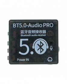
Szín: BT5.0 tokkal - Mini Bluetooth 5.0 dekóder kártya audio vevő BT5.0 PRO MP3 veszteségmentes lejátszó vezeték
225 Ft 409 FtBT5.0 Audio PRO Mini Bluetooth 5.0 MP3 Decoder Board Audio Receiver MP3 Lossless Player Wireless Stereo Music Amplifier Module Lithium battery charging Incoming call
BT5.0 Audio PRO continues the excellent basic functions of M28 (long-distance transmission, Bluetooth 5.0 backward compatible, lossless sound quality, etc.), and adds more user-friendly performance, as follows: Charge while putting: This product has a circuit of charging and discharging, which can directly charge the battery through the USB power supply, and Bluetooth can continue to work normally during the charging process, and truly realize the function of charging and discharging. Solve the pain point that some products can not be used during the charging process. When powered by USB alone: The red light flashes, indicating that the power supply is normal. When powered by a separate battery: The yellow light is always on, indicating that the battery power supply is normal; the yellow light flashes, indicating that the battery is low. When the USB and battery are connected at the same time: The red light flashes to indicate that the battery is charging; the red light always indicates that the battery is fully charged. (Note that if the USB input is suddenly disconnected during the charging and discharging process, there will be a few seconds of interruption due
to the charge and discharge mode switching at this time, after which Bluetooth will automatically restart, automatically connect and maintain the previous playback state) Incoming voice call function: After the Bluetooth is connected, turn on the call audio mode in the Bluetooth settings. If the phone calls, you can answer or hang up the phone through the PLAY/STOP button. You can choose to send from the microphone of the original headset (provided that the headset has a call function, which is a 4-segment type) or from the onboard microphone (default), see the function description for details. When the computer sound card is used: Tin the pads in the two boxes corresponding to the Sound Card on the back of the module, and then connect it to the USB interface of the computer through the USB cable, which can be used as a sound card. That is, the sound played by the computer is output through the audio interface of the module. See function description for details. (Not enabled by default) Product Size:
Product Features: -
Szín: BT5.0 Pro tokkal - Mini Bluetooth 5.0 dekóder kártya audio vevő BT5.0 PRO MP3 veszteségmentes lejátszó vezeték
319 Ft 580 FtBT5.0 Audio PRO Mini Bluetooth 5.0 MP3 Decoder Board Audio Receiver MP3 Lossless Player Wireless Stereo Music Amplifier Module Lithium battery charging Incoming call
BT5.0 Audio PRO continues the excellent basic functions of M28 (long-distance transmission, Bluetooth 5.0 backward compatible, lossless sound quality, etc.), and adds more user-friendly performance, as follows: Charge while putting: This product has a circuit of charging and discharging, which can directly charge the battery through the USB power supply, and Bluetooth can continue to work normally during the charging process, and truly realize the function of charging and discharging. Solve the pain point that some products can not be used during the charging process. When powered by USB alone: The red light flashes, indicating that the power supply is normal. When powered by a separate battery: The yellow light is always on, indicating that the battery power supply is normal; the yellow light flashes, indicating that the battery is low. When the USB and battery are connected at the same time: The red light flashes to indicate that the battery is charging; the red light always indicates that the battery is fully charged. (Note that if the USB input is suddenly disconnected during the charging and discharging process, there will be a few seconds of interruption due
to the charge and discharge mode switching at this time, after which Bluetooth will automatically restart, automatically connect and maintain the previous playback state) Incoming voice call function: After the Bluetooth is connected, turn on the call audio mode in the Bluetooth settings. If the phone calls, you can answer or hang up the phone through the PLAY/STOP button. You can choose to send from the microphone of the original headset (provided that the headset has a call function, which is a 4-segment type) or from the onboard microphone (default), see the function description for details. When the computer sound card is used: Tin the pads in the two boxes corresponding to the Sound Card on the back of the module, and then connect it to the USB interface of the computer through the USB cable, which can be used as a sound card. That is, the sound played by the computer is output through the audio interface of the module. See function description for details. (Not enabled by default) Product Size:
Product Features: -
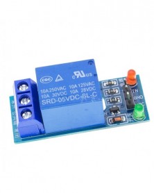
1 db 1 csatornás 5 V-os relémodul alacsony szint az SCM háztartási készülékek vezérléséhez Arduino-hoz
112 Ft 204 FtProduct introduction:
1, this module is in line with international safety standard, control areas and load area have the isolation groove;
2, USES the loose quality goods relay;
3, have power and relay operation instructions, and bright, disconnect the dawn;
4, signal input signal, the public end and will often start conduction;
5, can be used as a microcontroller development board module, can be used as a home appliance control;
6, dc or ac signal control, can control 220 v ac load;
7 and one often opened a normally closed contact;
8, blue KF301 terminal line more convenient. -
SIM900 GPRS/GSM Shield Fejlesztőkártya négysávos modul kompatibilis C71-hez
993 Ft 1 805 Ft100% brand new and high quality
The GPRS Shield is based on SIM900 module from SIMCOM and compatible with and its clones. The GPRS Shield provides you a way to communicate using the GSM cell phone network. The shield allows you to achieve SMS, MMS, GPRS and Audio via UART by sending AT commands (GSM 07.07 ,07.05 and SIMCOM enhanced AT Commands). The shield also has the 12 GPIOs, 2 PWMs and an ADC of the SIM900 module(They are all 2V8 logic) present onboard.
Features:
Quad-Band 850 / 900/ 1800 / 1900 MHz - would work on GSM networks in all countries across the world.
GPRS multi-slot class 10/8
GPRS mobile station class B
Compliant to GSM phase 2/2
Class 4 (2 W @ 850 / 900 MHz)
Class 1 (1 W @ 1800 / 1900MHz)
Control via AT commands - Standard Commands: GSM 07.07 & 07.05 | Enhanced Commands: SIMCOM AT Commands.
Short Message Service - so that you can send small amounts of data over the network (ASCII or raw hexadecimal).
Embedded TCP/UDP stack - allows you to upload data to a web server.
RTC supported.
Selectable serial port.
Speaker and Headphone jacks
Low power consumption - 1.5mA(sleep mode)
Industrial Temperature Range - -40°C to 85 °C
Size:8.5x5.7x2cm(approx)