Tesztberendezés alkatrészei és tartozékai
-
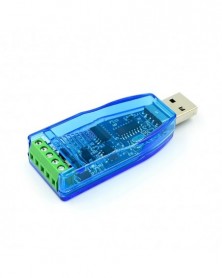
Szín: USB-RS485 - Ipari USB-RS485 kommunikációs modul kétirányú félduplex soros vonali átalakító TVS védelem
160 Ft 372 FtProduct parameter
1. Power supply: USB 5V
2. Transmission distance: 1200 meters (under 9600bps conditions)
3. Chip solution: CH340
4. Communication protocol: pure hardware equipment, not restricted by protocol
5. Baud rate: 921600bps, supporting mutual transmission supports higher baud rate
6. Protection: TVS transient suppression protection, electrostatic ESD protection, surge protection, AB signal line short-circuit and short-circuit protection with the power supply (short-circuit does not burn)
7. Temperature range: -40℃-80℃
8. Provide external 5V power supply with fuse for current limiting
9. Support system: support hot swap, support win98/CE/2000/2003/2008/XP/WIN7/WIN8/WIN10/VISTA/LINUX/MAC OS X system, USB interface can be hot swapped
10. Automatically identify and control the data transmission direction, without any handshake signals (such as RTS, DTR, etc.) without jumper settings to achieve mode conversion, to ensure compliance with the existing communication software and interface hardware.
11. Size: length, width and height 70*27*13mm -
Szín: USB-RS232 RS485 - Ipari USB-RS485 kommunikációs modul kétirányú félduplex soros vonali átalakító TVS védelem
265 Ft 616 FtProduct parameter
1. Power supply: USB 5V
2. Transmission distance: 1200 meters (under 9600bps conditions)
3. Chip solution: CH340
4. Communication protocol: pure hardware equipment, not restricted by protocol
5. Baud rate: 921600bps, supporting mutual transmission supports higher baud rate
6. Protection: TVS transient suppression protection, electrostatic ESD protection, surge protection, AB signal line short-circuit and short-circuit protection with the power supply (short-circuit does not burn)
7. Temperature range: -40℃-80℃
8. Provide external 5V power supply with fuse for current limiting
9. Support system: support hot swap, support win98/CE/2000/2003/2008/XP/WIN7/WIN8/WIN10/VISTA/LINUX/MAC OS X system, USB interface can be hot swapped
10. Automatically identify and control the data transmission direction, without any handshake signals (such as RTS, DTR, etc.) without jumper settings to achieve mode conversion, to ensure compliance with the existing communication software and interface hardware.
11. Size: length, width and height 70*27*13mm -
DC-DC DC nagy teljesítményű, állítható digitális kijelző, lefelé tartó tápegység modul állandó feszültség és
354 Ft 823 FtDescription
nstructions for use: Press the "Set" button to cycle through 4 display modes, the corresponding indicator will be on or off, press the "OK" button to save and exit, and press the "OK" button alone to turn on and off the backlight of the LCD screen.
Instructions:
(1) Adjust the "constant voltage potentiometer ADJ-V" to make the output voltage reach the voltage value you want;
(2) Directly short-circuit the output terminal of the module (just find a thick wire to short-circuit the output terminal), at this time adjust the "constant current potentiometer ADJ-I" to make the displayed current value reach the preset overcurrent protection value; ( For example, the current value displayed by the on-board ammeter is 4A, then the maximum current of the module is limited to 4A, and the red indicator light is on when the current reaches 4A)
(3) Connect the load and work.
2. Use as a battery charger
Instructions:
(1) Determine the floating voltage and charging current of the battery; (If the lithium battery parameter is 3.7V/2200mAh, then the floating voltage is 4.2V, and the maximum charging current is 1C, which is 2200mA)
(2) Under no-load conditions, adjust the "constant voltage potentiometer ADJ-V" to make the output voltage reach the float voltage;
(3) Directly short-circuit the output terminal of the module (just find a thick wire to short-circuit the output terminal), at this time adjust the "constant current potentiometer ADJ-I" to make the displayed current value reach the preset charging current value;
(4) The default charging current of the rechargeable lamp is 0.1 times the charging current; (The current of the battery is gradually reduced during the charging process, and gradually changes from constant current charging to constant voltage charging. If the charging current is set to 1A, then when the charging current is set to 1A, When the charging current is less than 0.1A, the blue light is off and the green light is on, and the battery is fully charged at this time)
(5) Connect the battery and charge it.
3. Use as a constant current LED driver module
(1) Determine the operating current and maximum operating voltage you need to drive the LED;
(2) Under no-load conditions, adjust the "constant voltage potentiometer ADJ-V" to make the output voltage reach the LED operating voltage;
(3) Directly short-circuit the output terminal of the module (just find a thick wire to short-circuit the output terminal), at this time adjust the "constant current potentiometer ADJ-I" to make the displayed current value reach the preset LED working current;
(4) Connect the LED and test the machine.
Note that the constant current adjustable current must be in constant current mode only when the actual load output current is greater than the set current, otherwise it will work in a constant voltage state. It is not the current that is adjusted to 2A, that is, it will become 2A if any equipment is connected. Know. -
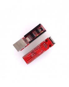
ENC28J60 Ethernet Shield V1.0 kompatibilis Nano 3.0 RJ45 webszerver modulhoz
273 Ft 634 FtDescription
Ethernet Shield Nano UNO R3, work as ENC28J60 RJ45 Webserver
100% Brand new
With this Ethernet Shield, Nano board can be used to connect to internet
controller: Microchip's ENC28J60 ethernet / HR911105A
works as server or client
comes with efficient library and examples
direct plug puzzle board, NO soldering needed -
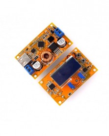
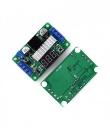
10A DC állítható LCD-kijelző CC CV lefelé tartó tápegység modul Boost átalakító 12v 24v 36v 40v 100w
760 Ft 1 768 FtModule parameters
Input voltage: 10-32V DC input
Output voltage: 11-60V DC continuously adjustable (It is recommended that the working voltage has a margin and should not exceed 55V. It is only suitable for applications where the input voltage is less than the output voltage and cannot be stepped down)
Output current: Maximum 8A and more than 4A, please strengthen heat dissipation (supporting fans are available in this shop! It is related to the input and output pressure difference, the greater the pressure difference, the smaller the output current)
Output power: Natural heat dissipation maximum 90W, enhanced heat dissipation maximum 150W
Module nature: non-isolated boost module (BOOST)
Output constant current range: 0.3-8A
Working temperature: -10~ 85 degrees (please strengthen heat dissipation when the ambient temperature is too high)
Working frequency: 150KHz
Conversion efficiency: up to 95% (efficiency is related to input, output voltage, current, and pressure difference)
Short circuit protection: none (do not use in short circuit)
Input reverse connection protection: None, please add an anti-reverse diode at the input end, available in our shop!
Output indicator light: with charging indicator, charging yellow, full blue
Output anti-backflow: Yes
Wiring mode: wiring terminal or welding terminal, IN is input, OUT is output
Module size: length 80mm width 53mm height 35mm -
PAM8610 digitális teljesítményerősítő kártya, 2 x 15w, kétcsatornás sztereó mini teljesítményerősítő kártya
120 Ft 279 FtDescription
The power amplifier board using the official standard circuit design, chip selection is used in the United States imported original Longding micro class D amplifier chip. This chip is not strong we can go to check it under the information.
Good product chip and the vast number of music lovers will share, this is our consistent philosophy! The power amplifier with high efficiency, large power, in the case of 12V power supply can output 10W 10 W power, the chip without heat sink, but also with overheating, overcurrent protection, features can be said to be very powerful.
The board has a switch function, the SW shorted, will close the amplifier. -
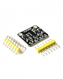
10 db/1 tétel VL6180 VL6180X távolságmérő optikai távolságmérő modul arduino I2C interfészhez 3.3V 5V
1 293 Ft 3 008 FtProductfeature:
For the convenience of customers!The input voltage of this module is 3.3V / 5V , which is more convenient for development and use!
VL6180X proximity, gesture and ambient light sensing (ALS) module.
Slider switch controlling 2 functions:
Ranging measurement, beyond 400mm.
Ambient light sensing, up to 100 kLux1.
4-digit display, displaying either the distance of a target from the proximity sensor, or the lux value from the ambient light sensing (ALS).
Excellent ranging accuracy, independent of the reflectance of the target.
Basic gesture recognition application can be developed with one or multiple VL6180X modules.
Compatible with STM32 Nucleo board family.
Equipped with arduinoTMUNO R3 connector.
RoHS compliant.
Wiring description:
1. The digital output of GPIO0 is 10 pins;
2.SDA pin of SDA connector development board;
3.SCL pin of SCL joint development board;
4. Power supply can be connected to 3.3V or 5V.
Instructions for module use:
1. Download the provided routine code to the WAVGAT development board;
2. Connect the VL6180 module with the development board according to the wiring instructions;
3. Open the serial port monitoring window of Arduino IDE;
4. When the sensor is not covered in front, the serial port monitoring window displays 255;
5. When there is occlusion, the distance is shown as measured distance and the unit is mm. -
TDA7850 4*50W autós audio teljesítményerősítő AMP kártya BA3121 zajcsökkentő modul XH-M150 DC 12V 4X50W 4X50
477 Ft 1 109 FtDescription
Fever class TDA7850 power amplifier board 4 channel car power amplifier board 4X50W with BA3121 noise reduction
TDA7850 car power amplifier board
Audio coupling capacitors use original audio coupling capacitors
The main filter capacitor uses a new original genuine 10000uf, more energy, bass is more low. The main chip TDA7850 adopts new original genuine, non-disassembled grinding parts
Using LC filter, the power supply is more pure, the ripple is smaller, the interference is smaller, and the BA3121 isolation noise reduction (elimination of common ground noise)
The circuit is reasonable in design, no noise when starting up, no need to connect the horn protection board 4 input / 4 output
DC 12V power supply or use 12V automotive power supply
There is no impact sound with delay function, no need to install horn protection -
USB-RS485 485 konverter adapter támogatás Win7 XP Vista Linux Mac OS WinCE5.0
95 Ft 222 FtUSB to RS485 Converter Adapter
USB connector: to your PC
RS485 connector: to your RS485 device
No need external power, powered by USB port
Fully compliant USB 2.0 standard , backward compatible with USB1.1
Specification:
Support System: Windows XP , Vista, Windows 7 , Linux , MacOS , and WinCE5.0 drive
Supports baud rate range : 75bps - 115200bps , up to 6Mbps
Work temperature range: -40°C ~ 85°C
Communication distance :1200m(max)
Dimension:6.1x1.6x1.3cm
Color: Black
Applications:
All kinds with RS485 port device parameter settings , data communication
Short distance , such as parameter settings of the computer peripheral equipment , the use of common data lines can be .
• LED display of communication data
• Machine PLC data reading and writing
• Monitoring data read and write , and PTZ control
• centralized control of household electrical appliances
• Access Control System ; card
• a variety of industrial automation ; instrumentation
• Parking ; bus fees
• Dining Hall ; staff attendance
• highway toll station; ATM machine -
8 tűs 4x4 4 * 4 mátrix 16 gombos billentyűzet billentyűzet Breadboard modul MCU arduino barkácskészlethez
76 Ft 176 FtProduct Description
100% Brand new and high quality
Good Quality button
Expanded development application modules
4x4 Matrix
Keypad Keyboard module 16 Button
Size: Approx.42mmX42mm / 1.65x1.65 -
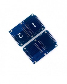
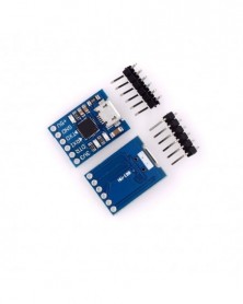
Diymore WeMos D1 Mini dupla foglalatos, kétalapú pajzsos fejlesztőkártya
75 Ft 175 FtFeature:
Dual bases for all Wemos D1 Mini modules and shields
Duplicates I/O and power
Warning: all I/O are designed to be 3.3V compliant only.
Package Included:
1 x WeMos D1 Mini Dual Base with Pin -
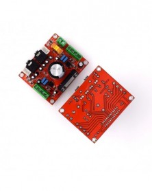
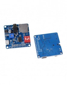
DY-SV5W MP3 zenelejátszó hanglejátszó erősítő modul 5 W SD/TF kártya integrált UART I/O trigger D osztály Arduinohoz
255 Ft 594 Ft1.Description:
DY-SV5W is an intelligent voice module developed by the division independently. It integrates I/O subsection triggering, UART serial port control, ONE_line single bus serial port control. Onboard 5W Class D amplifier circuit and can directly drive 4ohm 3~5W speakers.Support MP3,WAV decoding format. Max support 32Gbit(4MByte) TF card memory, can connect the computer to update TF card to store audio files via USB cable.3.5mm audio interface, U disk interface,Micro USB download interface, button module in one module
2.Features:
1>.Support MP3 and WAV decoding format.
2>.Support sampling frequency (KHz) : 8/11.025/12/16/22.05/24/32/44.1/48.
3>.24-bit DAC output, dynamic range support 90dB, SNR support 85dB.
4>.Support the FAT16/FAT32 file system, with the maximum support 32Gbit(4MByte) TF card and 32Gbit(4MByte) U-disk.
5>.Support UART serial port control voice broadcast function.It can control playback, pause, selections, turn up and down volume and other functions, the largest selection of 65535 songs.The baud rate is 9600 bit/s.
6>.Support I/O trigger function, 8bit I/O ports can trigger 8 musics or 8 I/O combinations to trigger 255 songs.
7>.Support One_line single bus serial port control, which can control playback, pause, selection, turn up and down volume and other functions.
8>.Support 3 configuration I/O for mode selection to make 7 work mode.
9>.Built in 5W Class D amplifier circuit and can directly drive 4ohm 3~5W speaker.
3.Parameters:
1>.Product Name:DY-SV5W Voice Playback Module
2>.Product Number:DY-SV5W
3>.Work Voltage:DC 5V
4>.Working Temperature range:-20~85 Celsuis
5>.Working Humidity range:0% -95% RH
6>.Size :40*40*9mm
4.Package:
1>.1pc DY-SV5W Voice Playback Module -
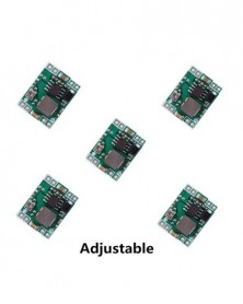
Szín: Állítható - Ultra-kis méretű DC-DC lépcsős tápegység modul MP1584EN 3A állítható Buck Converter Cserélje ki
215 Ft 501 FtDescription
1. Model Name: Ultra-small DC-DC step-down module
2. Input voltage: 4.5-28V
3. Output Voltage: 0.8-20V
4. Output current: rated current 3A(MAX).
5. Switching Frequency: 1.5MHz (highest), typical 1MHz
6. Output Ripple: < 30mV
7. Efficiency: 96% (max)
8. Operating temperature: -40 Celsius to 85 Celsius
9. Size: 22mm*17mm*4mm -
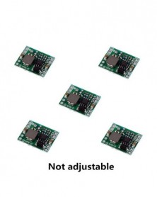
Szín: nem állítható - Ultra-kis méretű DC-DC lépcsős tápegység modul MP1584EN 3A állítható Buck Converter Cserélje
209 Ft 487 FtDescription
1. Model Name: Ultra-small DC-DC step-down module
2. Input voltage: 4.5-28V
3. Output Voltage: 0.8-20V
4. Output current: rated current 3A(MAX).
5. Switching Frequency: 1.5MHz (highest), typical 1MHz
6. Output Ripple: < 30mV
7. Efficiency: 96% (max)
8. Operating temperature: -40 Celsius to 85 Celsius
9. Size: 22mm*17mm*4mm -
Szín: MP1584EN - Ultra-kis méretű DC-DC lépcsős tápegység modul MP1584EN 3A állítható Buck Converter Cserélje ki az
221 Ft 514 FtDescription
1. Model Name: Ultra-small DC-DC step-down module
2. Input voltage: 4.5-28V
3. Output Voltage: 0.8-20V
4. Output current: rated current 3A(MAX).
5. Switching Frequency: 1.5MHz (highest), typical 1MHz
6. Output Ripple: < 30mV
7. Efficiency: 96% (max)
8. Operating temperature: -40 Celsius to 85 Celsius
9. Size: 22mm*17mm*4mm -
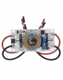
DC-DC Boost Converter állandó modul Áram mobil tápegység 10A 250W LED meghajtó Nem szigetelt Step Up modul
230 Ft 535 FtSpecification:
Module name: 250W boost constant current module
Module properties: non-isolated step-up module (BOOST)
Input voltage: DC 8.5V-48V
Input current: 10A (MAX) exceeds 8A please enhance heat dissipation
Quiescent current: 10mA (12V liter 20V, the output voltage, the higher the current will increase too quiet)
Output voltage: 10-50V continuously adjustable
Constant] range: 0.2-8A
Temperature: -40 -85℃ (ambient temperature is too high, please enhance heat dissipation)
Operating frequency: 150KHz
Conversion efficiency: up to 96%
Overcurrent protection: Yes
Input reverse polarity protection: Yes
Installation: 4 3mm screw holes
Connection method: Connection Output
Module size: 70mm x 36mm x 13mm
Application:
DIY a power supply, 12V can input and output can 12-50V adjustable.
The power supply for your electronic device, according to your system can set the output voltage value.
As the car power supply for your laptop, PDA or a variety of digital products supply.
DIY a mobile notebook power supply: 12V coupled with high-capacity lithium battery pack, so you can go where light where books.
Solar panel regulator.
To the battery, rechargeable lithium batteries. -
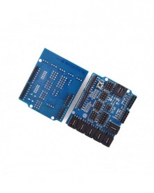
Smart Electronics Sensor Shield V4.0 V4 digitális analóg modul bővítő kártya
135 Ft 315 FtDescription
Each functional module has buckled port with VCC, GND and Output, which has corresponding port on the Sensor Shield, connected with a plain 2.54mm dual-female cable you may start playing already.
Buckled brick cables are like cement for bricks, make the connections easier, secure and more professional looking.
just plug & play.
Operating Voltage: 5VDC.
Input Voltage (recommended): 7-12VDC.
Input Voltage (limits): 6-20VDC.
Buckled Analog Port : Handy, solid connection to 6 Analog inputs with VCC/GND.
Digital IO port : 13 ports prepared to digital modules or servos.
Analog IO Port:2.54 grid male pin header connections.
Buckled Communication Port : Selectable between I2C and UARt.
Size:7cm x 5.8cm - 2.76inch x 2.28inch. -
LTC1871 100W/6A DC tápforrás Step Up Converter DC DC 3.5V-30V 5v 12v 6A 100W Állítható konverterek Piros LED Voltmérő
310 Ft 721 FtDescription
1. Input voltage range :3.5-30V Note: 30V maximum voltage limit must be aggressive in order to avoid accidental damage.
2. Output voltage range :3.5-30V (boost mode, the input must be less than or equal to the output voltage).
3. Input Current: 6A maximum 10A output power: 100W.
4. Note: According to the law of conservation of power output current under nominal conditions.
5. UIN * Iin * efficiency = Uout * Iout (UIN: input voltage Iin: input current).
6. Size: 66mm * 42mm * 18mm Weight: 35 g / pcs.
7. The voltmeter accuracy: ± (5 ‰ 1 word).
8. Static power consumption: Typical 15ma
(input voltage output voltage and the digital tube color is closely related to the actual current deviation).
9. IN : Input the cathode IN-: Input negative OUT : the output cathode OUT-: Negative output.
Features:
1: input and output voltage can be alternately displayed.
2: switched on can be freely defined.
3: with a button to turn off the digital control function, reduce power consumption.
Working mode:
Output voltage mode: the default boot display ** output voltage mode. * LED indicator turns off
Input voltage mode: press the switch once to switch to the input voltage mode **. * LED indicator lights
Alternating pattern: Once again press the switch input / output voltage alternating 3S alternately display data
(press again to return to the display mode of the output voltage)
Operation and digital display description:
[0] represents the default the boot display output voltage
[1] represents the default boot display input voltage
[2] represents the default open to input and output voltage are displayed alternately
Long press the button more than 2S digital tube display more information (in this case the key is released),
the module automatically remembers the current state of the default power-on state.
The digital tube close operation: long press button 4s until the digital tube display the contents of the LED is lit,
the display section has been closed. Press the button again to restore the display
Data test (voltmeter turned on):
3.7V turn 5V/2A efficiency of 82.5%
5V to 12V/2A efficiency of 88.4%
7.4V turn 12V/2A efficiency of 90.2%
12V switch 18V/2A efficiency of 93.6%
18V switch 24V/2A efficiency of 95.3%
24V turn 30V/2A efficiency of 97.1%
Summary: The higher the input voltage, the higher the efficiency. Close the voltmeter boost module will get higher efficiency.
Package included:
1PCS x LTC1871 100W 3.5V to 30V Power Supply DC-DC Step up Module LED Voltmeter -
Leléptető tápegység modul DC4-40v DC1,25-36v 8A 200w Állítható XL4016E1 DC-DC DC feszültségszabályozó
177 Ft 411 FtProduct Description
XL4016E1 DC-DC step-down module, high power DC regulator, 8A, voltage stabilizing and step-down module.
1. please keep the input and output differential pressure above 2V.
2. the long distance running current is recommended in 5A. If the power is too large, please increase the fan or other ways to enhance the heat dissipation.
3. this module is a buck module, not a boost module.
Input voltage: dc4-38v
Output voltage: dc1.5-36v
Output current: 8 a.
Power: 250W -
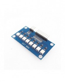
Szín: HW-043 Piros - 5050 RGB színes LED / vízlámpa modul mikrokontroller futóvíz lámpa
123 Ft 286 FtFunctional characteristics
8 bit three primary colors (red, green and blue) full color LED, scanning is control mode.
The same as the digital control method, the bit selection control corresponds to the LED lighting, and the segment control color.
Different color changes can be produced through different programs.
Suitable for 51/AVR/AVR/ARM/ard uino and other platforms.
The eight legs of D0-D7 control the eight LEDs respectively, so just connect the digital pins that correspond to Ard uino (as long as we connect the experiment to 2-9 pins in turn). There are three RG B feet beside it, which need to be connected with GND, bright red with R, bright green with G, bright blue with B, and all three at the same time. -
Szín: HW-043 Bule - 5050 RGB színes LED / vízlámpa modul mikrokontroller futóvíz lámpa
123 Ft 286 FtFunctional characteristics
8 bit three primary colors (red, green and blue) full color LED, scanning is control mode.
The same as the digital control method, the bit selection control corresponds to the LED lighting, and the segment control color.
Different color changes can be produced through different programs.
Suitable for 51/AVR/AVR/ARM/ard uino and other platforms.
The eight legs of D0-D7 control the eight LEDs respectively, so just connect the digital pins that correspond to Ard uino (as long as we connect the experiment to 2-9 pins in turn). There are three RG B feet beside it, which need to be connected with GND, bright red with R, bright green with G, bright blue with B, and all three at the same time. -
LM2596 DC DC Step Down Converter Feszültségszabályozó LED Kijelző Voltmérő 4,0-40-1,3-37V Buck Adapter Állítható
144 Ft 336 FtFeatures:
1. With voltmeter display, voltmeter error is ± 0.1V, range is 4 ~ 40V. (Note: the input voltage is lower than 4V, the onboard voltmeter does not work and does not display)
2. Large volume 5 * 5 touch the button to switch between measuring input or output voltage, and an indicator light shows which terminal voltage is being measured. By default, the digital tube displays the input voltage and the input indicator IN is on. When the button is touched, the digital tube displays the output voltage and the output indicator OUT is on. And keep the last setting, even after power off
3. The voltmeter can be turned off. Press and hold the switch for more than 1 second and less than 4 seconds. After the voltmeter is turned off, just press the switch briefly to turn on the voltmeter.
4. The input and output voltage measurement error calibration function, long press the switch for more than 4 seconds, and enter the voltage measurement error calibration function after releasing the hand. At this time, the IN light is on (calibrating the input terminal), and the digital tube flashes to display a more positive value (factory parameter is 0.0). At this time, you can change this value by pressing the button shortly (the value range is -0.5 ~ 0.5, the unit is V). A positive number indicates upward calibration, and a negative number indicates downward calibration. After adjusting the calibration value of the input terminal, press and hold the button for more than 2 seconds, and enter the error calibration of the output terminal after releasing. At this time, the OUT light is on (calibrating the output terminal), and the calibration value of the output terminal is displayed. The adjustment method is the same as that of the input terminal. After the calibration value at the output end, press and hold the button for more than 2 seconds, and save the set value and return to the normal display voltage after letting go, the set correction value will take effect immediately and will not be lost after power failure. (With this function, you can meet your higher accuracy requirements)
5.With terminal block, it is convenient to use without soldering iron, and the welding wire connection point is reserved
(The input voltage must be more than 1v higher than the voltage to be output)
6. The maximum output current can be as high as 3A. It is recommended that the working current be about 2A.
7. It adopts the internal oscillation frequency of 150KHz, which belongs to the second-generation switching voltage regulator, with low power consumption and high efficiency.
Scope of application
This module can be used in step-down fields where the input voltage is higher than the output voltage, such as batteries, power transformers, DIY adjustable regulated power supplies, 24 car pen-based power supplies, industrial equipment step-down, 12V to 3.3V, 12V to 5V, 24V to 5V, 24V to 12V, 35V to 24v, etc.
Self-calibration method of on-board voltmeter:
1. Input and output voltage measurement error calibration: long press the switch for more than 4 seconds, and after letting go, it will enter the voltage measurement error calibration function. At this time, the IN light is on (calibration input terminal), and the digital tube flashes to display the positive value (the factory parameter is 0.0 ), at this time, short press the button to change this value (the value range is -0.5~0.5. The unit is V), a positive number means upward calibration, and a negative number means downward calibration. After adjusting the calibration value of the input terminal, press and hold the button for more than 2 seconds. After letting go, enter the error calibration of the output terminal. At this time, the OUT light is on (calibration output terminal), and the calibration value of the output terminal is displayed. The adjustment method is the same as that of the input terminal. After the calibration value of the output terminal, press and hold the button for more than 2 seconds. After letting go, save the set value and return to the normal display voltage. The set correction value will take effect immediately and will not be lost after power failure. (With this function, you can meet your higher precision requirements)
2 Turn off the voltmeter: Press and hold the switch for more than 1 second and less than 4 seconds, and then let it go to turn it off. After the voltmeter is closed, simply press the switch to turn on the voltmeter.
Some customers reported that the output voltage of the module cannot be adjusted and is always equal to the input voltage. When you encounter this kind of problem, please turn the potentiometer counterclockwise for more than 10 turns, and then use the module to adjust the voltage normally. Because when the step-down module leaves the factory, the default output voltage is about 20V.
Module usage tutorial:
1. The input and output voltage measurement error is more accurate: press and hold the switch for more than 4 seconds, and the voltage measurement error comparison function is entered after releasing the hand. At this time, the IN light is on (calibrating the input end), and the digital tube flashes to display a more positive value (the factory parameter is 0.0 ), At this moment, press this button to change this value (the value range is -0.5 ~ 0.5, the unit is V), positive number means upward calibration, negative number means downward calibration. After adjusting the calibration value of the input terminal, press and hold the button for more than 2 seconds, and enter the error calibration of the output terminal after releasing. At this time, the OUT light is on (calibrating the output terminal), and the calibration value of the output terminal is displayed. The adjustment method is the same as that of the input terminal. After the calibration value at the output end, press and hold the button for more than 2 seconds, and save the set value and return to the normal display voltage after letting go, the set correction value will take effect immediately and will not be lost after power failure. (With this function, you can meet your higher accuracy requirements)
2. Turn off the voltmeter: long press the switch for more than 1 second and less than 4 seconds, you can turn it off with a loose hand. After the voltmeter is turned off, just press the switch briefly to turn on the voltmeter.
Precautions:
1. It is recommended to use a heat sink to enhance heat dissipation when the power usage exceeds 15W.
2. Some customers report that the module output voltage cannot be adjusted and is always equal to the input voltage. When you encounter this problem, please turn the potentiometer counterclockwise more than 10 times before using the module to adjust the voltage normally. Because when the buck module leaves the factory, the default output voltage is about 20V. -
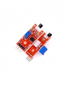
10 db/tétel LM393 3,5-24V feszültség-összehasonlító modul magas szintű kimeneti analóg komparátor vezérlés LED
767 Ft 1 783 FtProduct Description
1.Input Voltage:4.5-28V
2.Comparator Chip:LM393
3.Size:39.5*17mm
4.Application:for NTC thermosensitive temperature sensor,photosensitive sensor
5.Using Method:by reference voltage adjusting potentiometer to generate reference voltage,and compare voltage generated by sensor and divide resistor with reference voltage,achieving high/low level comparision result output -
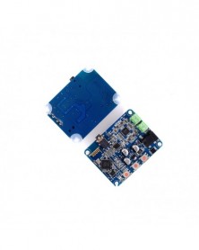
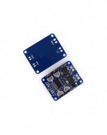
Bluetooth hangszóró új tábla Bluetooth digitális teljesítményerősítő vezeték nélküli vételi
686 Ft 1 596 FtDescription
he materials and workmanship are good, and the sound quality is very good. With a power amplifier, it can directly drive 4 ohm ~ 16 ohm speaker speakers, v4.0 Bluetooth, backward compatible with all Bluetooth versions, full power output 2x10W
Product parameters:
Three buttons
Power supply voltage: 12VDC (<15VDC)
Power supply interface: 2.1/5.5 DC seat
Power supply current: not less than 2A power supply (recommended)
Audio input method: Bluetooth receiver V4.0
Audio output mode: terminal block
Number of channels: two-channel stereo -
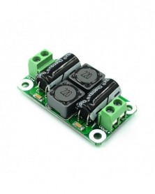
Egyenáramú tápszűrő kártya 0-25V/0-50V 2A/3A/4A D osztályú teljesítményerősítő modul Zavarszűrő kártya EMI
111 Ft 257 FtFeatures:
DC power supply filter board Digital power amplifier interference suppression board Automotive power supply EMI suppression, current 4A, can meet
The current of the TPA3116 machine makes the power input more pure, so the amplifier is less noisy.
low voltage DC (0V~50V)
Terminal description:
Vin : input positive end
Vin-: input negative
Vout : output positive end
Vout-: negative output -
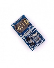
I2C RTC DS1307 AT24C32 valós idejű óramodul AVR ARM PIC-hez Apró RTC I2C modulok memória DS1307 óra
78 Ft 182 FtDS1307 I2C real-time clock chip (RTC) 24C32 32K I2C EEPROM memory
Using LIR2032 rechargeable lithium battery, and with a charging circuit to solve the problem of DS1307 with spare battery can not read and write. After fully charged, it can provide DS1307 timekeeping for 1 year. Small design, 27mm*28mm*8.4mm
Lead out the clock pin of DS1307 to provide the clock signal for the microcontroller. Other I2C devices can be cascaded. -
WTV020 WTV020-SD WTV020SD-20SS Mini SD kártya MP3 hangmodul hangmodul PIC Arduino 2560 UNO R3 WTV020-SD-16P számára
125 Ft 290 FtFeatures:
Products for WTV020 chip module plug the SD card, supports 32M ~ 1GBit capacity card;
Supports the FAT file system, SD card as storage medium;
And supports playback of WAV format files 4Bit ADCPM;
Supports automatic speech recognition folders and file playback;
You can play background music and commercials language;
Control methods are key control, second control and UART232 serial control;
WTV master chip has WTV020-16SOP and WTV020-20SOP two packages, both of which are compatible;
You can play any segment of speech;
Operating voltage: DC2.6 ~ 3.6V;
Classified by folder store content, easy to operate.
2 Product Overview
WTV020 plug-in SD card Voice module, the main chip selection WTV020-16S and WTV020-20S package chips. Voice updates directly through an SD card reader on a PC replacement. Control is also an SD card stored in TXT file changes. The module supports the FAT file system. Support and ADPCM WAV file playback. Supports two-wire serial control mode, key methods and UART232 serial manner. Automatic speech recognition and speech sample rate format. -
HT1632 pontmátrix illesztőprogram MCU rácsos kitörési kártyával, LED HT1632C modul 8X32 piros pontmátrix képernyővel
485 Ft 1 129 FtFeatures:
Using HT1632C lattice dedicated driver chip driver four monochrome 8 * 8 common cathode red dot matrix unit, consisting of a 8X32-resolution dot matrix screen.
Coming with Scan function
Using a conventional serial interface communication: CS = chip select lines, RD = read operation, WR = write operation, DATA = data lines. Need MCU scanning, support 16 brightness adjustment.
The internal register operations flashing function, so that all flashing function display LED blinking, opening rate of 0.25s; 0.25s off. There are data mode and command mode.
Own internal 256KHz RC oscillator that can be used for multiple modules screen use.
Dot-matrix screen to support all MCU control: for example C51, AVR, RAM, etc., only three common microcontroller IO port.
Applications:
Data instrument displays, LED displays.
calendar, digital clock, thermometer, counters, voltmeters.
Specifications:
Resolution: 8X32
The working voltage: 2.4-5.5V
Current: minimum brightness: 30mA
Maximum brightness: 300mA (test voltage 5V).
Shell color: blue
Dot Matrix Screen: Red
Size: 15.2 * 3.8 (cm) cm.
Package Included:
1*Lattice-Breakout LED HT1632C Module 8X32 Red Dot Matrix Screen -
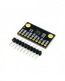
ICM-20948 érzékelőmodul legkisebb teljesítményű 9 tengelyes MEMS mozgáskövető eszköz érzékelő kártya CJMCU-20948
1 166 Ft 2 712 FtDescription:
The ICM-20948 is specifically designed to coordinate the time between the ICM-20948 and external sensors.
An extra feature. In addition to using the module's dedicated interrupt INT pin, developers can use the external sensor's interrupt or sync pulse to drive the module's FSYNC pin to help developers simplify these multi-sensor designs. The ICM-20948 provides separate external sensors. 12C interface and built-in support. Developers here connect a 12C-compatible smart sensor to the module's dedicated auxiliary 12C port. While the SPI (or 12C) is connected to the host MCU, the developer can use the TDK tube to stream the InvenSense ICM-20948 module's auxiliary 12C interface (AUX_CL Connect external sensors to AUX_DA and manage them via the auxiliary device special registers of the lCM-20948.
Features:
Lowest Power 9-Axis Device at2.5 mW
3-Axis Gyroscope with Programmable FSR of
250 dps, 500 dps, 1000 dps,and 2000 dps
3-Axis Accelerometer with Programmable FSR of 2g,±4g, 8g,and t16g
3-Axis Compass with a wide range to 4900 T
Onboard Digital Motion Processor (DMP for Android support
Auxiliary 2C interface for external sensors
On-Chip 16-bitADCs and Programmable Filters
7 MHz SPI or 400 kHz Fast ModeIC
Digital-output temperature sensor
VDD operating range of 1.71V to3.6V
MEMS structure hermetically sealed and bonded atwafer level
Pins Definition:
VCC: power terminal
GND: Ground
SCL: I2C serial clock interface
SDA: I2C serial data interface
NCS: used to read all data from the MPU and configure the MPU and external sensors
ADO: SDO pin when using SPI
INT: Interrupt pin
FSY: related to the external sensor part
ACL: Auxiliary 12C serial clock line
ADA: Auxiliary 12C serial data line -
HG7881 4 csatornás meghajtó egyenáramú motor meghajtó kártya motor meghajtó modul Smart Aar 4-utas meghajtó
185 Ft 431 Ftdescription
Material: Metal, Plastic Net Weight: 12g Model: HG7881 Main Color: Blue Input: DC 2.4-10VMaterial: Metal, Plastic
Net Weight: 12g
Model: HG7881
Main Color: Blue
Input: DC 2.4-10V
Fixing Hole Dia: 3mm
Board Size: 50 x 36mm/2x 1.4 inch(L*W)
HG7881 4 channels driver step-up module for DC motor, high effiency.
Small size and light weight.
Package Content: 1 x DC Motor Driver Module Board
Note: Light shooting and different displays may cause the color of the item in the picture a little different from the real thing. The measurement allowed error is /- 1-3cm -
1 db 16 bites ADC 8 csatornás szinkronizációs AD7606 adatgyűjtő modul 200 Ksps
1 358 Ft 3 158 FtProdect description:
Tip : To facilitate your choice , PCB board analog input front -row pin (2x8/2.54mm pitch ) default not weld .
We will be giving away 2x8 's double needle and eight jumpers from the customer's own choice is up welding,
soldering or down .
1, using high-precision 16-bit ADC chip AD7606
2,8 analog inputs. 1M ohm impedance.[No negative supply, there is no front-end analog amplifier can be
connected directly to the sensor output]
3, the input range of plus or minus 5V, plus or minus 10V. By IO control.
4, Resolution 16.
5, the maximum sampling frequency sampling rate of 200ksps.
Supports eight sampling settings file (which can effectively reduce the jitter)
6, built-in benchmark
7, a single 5V power supply
8, SPI Interface, or 16-bit bus interface. Interface IO level can be 5V or 3.3V.
We AD7606 module factory default is 8080 parallel interface.
If SPI interface mode, you need to modify R1 R2 resistor configuration.
Parallel Mode Jumper: R1 floating (not stickers), R2 10K resistor paste
SPI interface mode jumper: R1 stickers 10K resistor, R2 floating (not stickers)
AD7606 configuration is very simple, it has no internal registers.
Range and over-sampling parameters are controlled via an external IO.
Pulse frequency sampling rate provided by the microcontroller or DSP control.
AD7606 must use a single 5V supply.
Level communication interface between the AD7606 and SCM controlled by VIO pin.
That VIO power supply must be connected to the microcontroller can be 3.3V can also be 5V.
[Module Pin Description]
OS2 OS1 OS2: a combination of state selection oversampling mode.
000 means no oversampling, the maximum sampling rate of 200ksps.
001 represents two times oversampling, which is the hardware inside collected two samples averaging
010 represents four times oversampling, which is the hardware inside collect four samples averaged
011 represents eight times oversampling, which is the hardware inside collected eight samples averaged
100 represents 16 times oversampling, which is the hardware inside collected 16 samples averaged
101 represents 32 times oversampling, which is an internal hardware averaging collected 32 samples
110 represents 64 times oversampling, which is the hardware inside collected 64 samples averaged
Oversampling ratio is higher, the longer the ADC conversion time, the lower the maximum sampling
frequency can be obtained.
CVA, CVB: AD conversion start control signal channel 1-4 decision CVA, CVB decided 5-8 channels.
Two signals can stagger a short time, in general, can be CVA, CVB parallel together.
RAGE: Select the range of 0 means plus or minus 5V, 1 indicates negative 10V.
RD: Read signal
RST: Reset signal
Busy: Busy Signal
CS: chip-select signal
FRST: first a channel samples indicating signal
VIO: communication interface level
DB0 - DB15: Data Bus
[16 parallel mode wiring diagram --- AD7606 also supports 8-bit bus mode, see the AD7606 data sheet
MCU side AD7606 module
GND <----- ground
5 V <----- 5V power supply
RAGE <----- can also be connected to the GPIO connected fixed level
OS2 <----- can also be connected to the GPIO connected fixed level
OS1 <----- can also be connected to the GPIO connected fixed level
OS0 <----- can also be connected to the GPIO connected fixed level
CVA <----- access the GPIO (output) is used to start AD conversion [Recommended pick pin with PWM output
capability]
CVB <--- |
RD <----- 8080 bus read signal NOE
RST <----- GPIO output hardware reset AD606
Busy -----> GPIO input AD606 being converted instructions. [Recommended connection with external
pin interrupt capability]
CS <----- 8080 bus chip select NCS
VIO <----- microcontroller power supply
DB0-DB15 -----> 8080 data bus (16)
FRST may take
[SPI interface mode wiring diagram
MCU side AD7606 module
GND <----- ground
5 V <----- 5V power supply
RAGE <----- any output GPIO, can be accessed by a fixed level
OS2 <----- any output GPIO, can be accessed by a fixed level
OS1 <----- any output GPIO, can be accessed by a fixed level
OS0 <----- any output GPIO, can be accessed by a fixed level
CVA <----- access the GPIO (output) is used to start AD conversion [Recommended pick pin with PWM
output capability]
CVB <--- |
RD / SCLK <----- SPI bus clock SCK
RST <----- any output GPIO, for hardware reset AD606
Busy -----> GPIO input, AD606 being converted instructions. [Recommended connection with external
pin interrupt capability]
CS <----- SPI bus chip select SCS
VIO <----- microcontroller power supply
DB7 (DOUTA) -----> SPI bus data lines MISO
DB14 - DB15 may pick
FRST may take
Software implementations [1] --- timing acquisition of SPI example we offer document using this program,
see bsp_spi_ad7606.c
In the timer interrupt service routine implementation:
Timer interrupt ISR:
{
Interrupt entry;
8 reads the sampling results are stored in the RAM channel; ----> read is the last record collection for continuous
acquisition, it is not related to the
Start next ADC acquisition; (flip CVA and CVB)
Interrupt return;
}
Timer frequency is the ADC sampling frequency. This mode can not connect busy port cable.
Software implementations [2] --- timed 8080 acquisition of the interface we provide an example of using
this program, see bsp_ad7606.c file
Configure CVA CVB pin PWM output mode, the sampling period is set to the desired frequency; ---> After
the MCU will produce a very stable AD conversion cycle signal
The busy port line is set to interrupt falling edge trigger mode;
External interrupt ISR
{
Interrupt entry;
8 reads the sampling results of the channel stored in the RAM;
Interrupt return;
}
[1 and 2, the differences in implementations of software-timed acquisition]
(1) Option 1 may be less busy lines, but the other main interrupt service routine or temporary closure of
the global interrupt when ADC conversion cycle may cause a slight jitter.
(2) Option 2 can ensure the stability of the acquisition of the clock, because it is generated by the MCU
hardware, but need more then a BUSY mouth lines. -
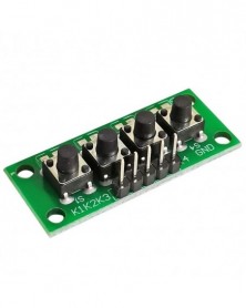
5 db/tétel 1x4 4 független billentyűs gombos billentyűzet Billentyűzet modul Mcu arduino-hoz Diákosztály tervezés
166 Ft 387 Ft1.Size:37*15*11mm
Package Included:
5PCS 1x4 4 Keys Button 5Pin Keypad Keyboard Breadboard Module for arduino -
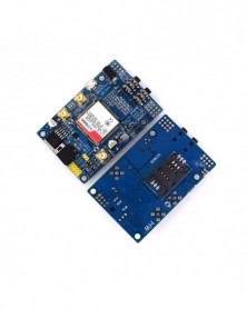
SIM808 SIM908 modul helyett GSM GPRS GPS fejlesztőtábla IPX SMA GPS antennával Raspberry Pi-hez
1 171 Ft 2 723 FtDescription:
1.Three power input interface: DC044 interface and V_IN and a lithium battery interface.
Note that: The range of DC044 and the V_IN pin voltage input is 5 - 26V, when use the 5V as the power, be sure that the power supply can provide 2A current. The range of voltage of Lithium battery input power is 3.5 - 4.2V.
2. Switch: It is used to open / close the input power supply for the module. When in use, please confirm the toggle switched to the OPEN state (near the board inside).
3. SMA antenna interface: there is a GSM antenna interface, a GPS antenna interface onboard and a BT antenna interface.
4. Start button: When the board is power on, the LED (PWR) will light up. After a long press (about 2 second) on this button, the other three LEDs will be light. And one of them starts to flash; this suggests that SIM808 is beginning to work now. When the power supply, GSM and GPS antenna and SIM card are connected to the module correctly, the LED will be flash slowly (3Second de 1second light), that indicates that the module is registered to the network, and you can make a call or do something else.
5. TTL serial interface: a TTL level interface. Notice that: The pin of VMCU is used to control the high level of TTL UART, so as to realize to match between 1.25V/3.3V /5V systems. For example, if you want to use the 51 MCU to control this board, the pin of VMCU should be connected the DC5V. And if use the STM32 MCU, the pin of VMCU should be connected the DC3.3V. The pins of RXD is the RXD of SIM808 and the pins of TXD is the TXD of SIM808. The pin of V_IN can connect the Power, the function of this pin has the same function of DC044.
6. USB interface: This interface is just use to update the firmware of SIM808 module.
Operation Description:
1. Preparation:
SIM808 SHIELD
DC9V adapter
USB-TTL module or other tools.
PC software
2. Hardware configurations
2.1 Connect the USB-TTL to the UART interface
USB-TTL SIM808
TXD RXD
RXD TXD
GND GND
2.2 Insert the valid SIM card to the SIMCARD holder.
2.3 Connect the GPS antenna and GSM antenna to the board
Connect the power adapter to the DC044 Interface
2.4 Change the switch
2.6 Press the POWKEY button for 2 second, the SIM808 module will work and the other 3 LEDs will light.
Document Link:https://www.adrive.com/public/P7QRkq/FZ1735-SIM808% 20% E5% A4% A7V3.1.rar
Package Included:
1 X SIM808 Moudle
1 X GSM Antenna
1 X GPS Antenna -
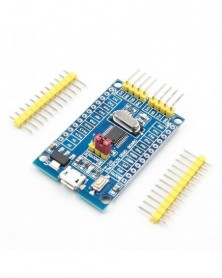
48 MHz STM32F030F4P6 kis rendszerfejlesztő kártya CORTEX-M0 Core 32 bites mini rendszerfejlesztő panelek
207 Ft 482 FtProduct Description
This board is a STM32F030F4P6 Minimum System Board(Cortex-M0). The target MCU is STM32F030F4P6 that is provided by ST. It is a ARM 32-bit Cortex?-M0 CPU, frequency up to 48 MHz, high-speed embedded memories . As a minimal ready-to-run system, this board integrates micor USB power supply interface, ISP/SWD programming/debugging interface, boot mode selection and so on to take you into the ARM Cortex world easily. -
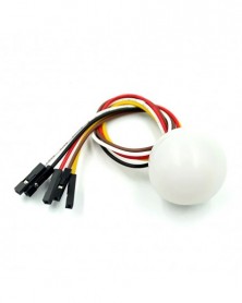
BH1750 BH1750FVI digitális fényérzékelő modul chip fényintenzitású fénymodul fénygömb arduinohoz
165 Ft 384 FtProduct Description
Product Description
parameter
1. The outer diameter is 26mm, the large rim diameter is 28.5mm, and the height is 26mm (plus light ball)
2. Working voltage: DC5V
3. Communication interface: I2C
4. Input light range: 1-65535lx
5. Spectral sensitivity characteristics: typical peak sensitivity wavelength: 560nm
6. Weak dependence on light source: incandescent lamp, fluorescent lamp, halogen lamp, white LED, fluorescent lamp can be used -
DC8-24V TPA3118 PBTL 60W Mono Digital Audio Erősítőkártya AMP modul Chip 1X60W 4-8 Ohm
222 Ft 517 FtSpecification:
The sound quality is very good using this module.
Mono digital audio amplifier chip.
High output and low power consumption.
Applicable speaker impedance: 4-8 ohms (8 ohms is the best).
Product specification:
Operating voltage: DC8-24V
Output power: 60W
PCB board size: 45*35mm/1.77*1.4in
Weight: 12g/0.43oz -
I41 CJMCU CP2102 MICRO USB - UART TTL modul 6 Pin soros átalakító UART STC Cserélje ki az FT232-t
125 Ft 290 FtDescription
1, the original chip CP2102, generate COM port after installing the driver.
2, then the standard input MICRO MINI-USB cable connected to the computer USB interface, with 3.3V and 5V two power output
3, with a resettable fuse. In the event of accidental short-circuit can effectively protect your device and computer USB port to download
4, on-board status indicators, receiving indicator properly installed drive status indicator remains, send and receive indicator flashes when the communication with run LED indicator.
5, supports baud rates from 300bps ~ 1Mbps between
6, the communication format support: 1) data bits 5,6,7,8; 2) support 1.5, 2 stop bits; 3) odd, even, mark, space, none parity
7, supported operating systems: windows 8.1 / 7 / vista / xp / 98, Mac OS-X / OS-9, Linux
8, USB seat MICRO MINI-USB interface Block
9, chip components for the regular company of welding, stable quality, beautiful appearance
10 with DTR trigger signal output can be directly pro mini ATMEGA328P and other board download traffic.
11, module size: 16mm * 20mm super small.
Features:
1. embedded USB transceiver, no external circuit device
2. containing clock circuit, no external circuit device
3. contains power-on reset circuit
The on-chip voltage regulator within the 3.3V output
5. Meet the USB2.0 specification requirements
6.SUSPEND pins support USB suspend state
7. asynchronous serial data bus compatible with all handshakes and modulation controller interface signals
8. Support data format is 8 data bits, 1 stop bit and the parity bit
9. connotation 512 byte receive buffer and 512 byte transmit buffer
10. Supports hardware or X-ON / X-OFF Handshake
How to install the driver
win7 / win8
1, first open the package, like the way next, remember installation directory
2, according to the following method to start the service
3. Locate the driver in Device Manager, select Update Driver, browse my computer for driver,
select the directory just installed, determine waiting like
win8.1
Right update drivers automatically find the drivers, it will prompt the driving data is invalid, in fact, the problem often encountered in windows8, the drive is no problem, the beginning has been installed on, and later discovered may be a hardware incompatibility.
If you are using Windows8 or windows 8.1, but is non-genuine ghost or other systems, and uses a variety of optimization tools Streamlining system, then in the process of installing the driver, you may encounter the "Data invalid" wrong
"Invalid Data" solutions are as follows:
1, press Winkey R on the keyboard, the pop-up "Run" dialog, enter "services.msc",
also by under "Computer Management" window, find the "service";
2, found in the list of services "Device Install Service" and "Device Setup Manager" two service items,
make sure these two services is turned on, if not open, you can click the left side of the "Start" service.
Package Included:
1 x CP2102 MICRO USB to UART TTL Module 6Pin Serial Converter STC Replace FT232 NEW -
DC-DC 24V/12V – 5V 5A Leléptető tápegység Buck Converter Cserélje ki az LM2596S állítható USB-leléptető
165 Ft 383 FtProduct Description
1: Working voltage: DC 9V - 36V;
2: The output voltage: 5.2V / 5A / 25W
3: Output capability:
9 ~ 24V Input: Output 5.2V / 6A / 30W
24 ~ 32V Input: Output 5.2V / 5A / 25W
32 ~ 36V Input: Output 5.2V / 3.5A / 18W
4: Size: 63 * 27 * 10cm (L * W * H) -
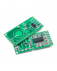
5 DB/LOT RCWL-0516 Mikrohullámú radarérzékelő modul Emberi test indukciós kapcsolómodul Lntelligens érzékelő
156 Ft 362 FtProduct Description
RCWL-0516 is a Doppler radar technology, specialized in the detection of moving objects in the microwave induction module.
The module has the characteristics of high sensitivity, high induction distance, high reliability, large induction angle, wide power supply voltage range, etc. it is widely used in various kinds of human body induction lighting and alarm and so on.
Characteristic:
Using special signal processing control chip RCWL-9196
Wide operating voltage range: 4-28V
Compared with the traditional infrared induction PIR, the penetration detection ability
Blocking time, adjustable distance
Can output 3.3V power supply -
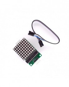
MAX7219 pont LED mátrix modul LED kijelző vezérlő modul 5 V interfész modul 8 x 8 kimeneti bemenet közös katód
174 Ft 404 FtDescription
MAX7219 is an integrated serial input/output common-cathode display driver. It connects a microprocessor and an 8-digit 7-segment digital LED display. It can also be connected to a bar graph display or 64 independent LEDs. It includes an on-chip B-type BCD encoder, multiple scan loops, segment word drivers, and an 8*8 static RAM to store each data. There is only one external register used to set the segment current of each LED.
A convenient four-wire serial interface can be connected to all general-purpose microprocessors. Each data can be addressed without rewriting all the displays when updating. MAX7219 also allows users to select encoding or not encoding for each data.
The entire device includes a 150μA low-power shutdown mode, analog and digital brightness control, a scan limit register allowing users to display 1-8 bits of data, and a detection mode that allows all LEDs to emit light.
Module parameters:
1. A single module can drive an 8*8 common cathode matrix
2. Module working voltage: 5V
3. Module size: length 5 cm X width 3.2 cm X height 1.5 cm
4. With 4 fixing screw holes, the hole diameter is 3mm, which can be fixed by our M3 copper column
5. Module with input and output interface, support multiple module cascade
Wiring instructions:
1. The left side of the module is the input port, and the right side is the output port.
2. When controlling a single module, you only need to connect the input port to the CPU
3. When multiple modules are cascaded, the input terminal of the first module is connected to the CPU, the output terminal is connected to the input terminal of the second module, the output terminal of the second module is connected to the input terminal of the third module, and so on. ..
Take 51 single chip microcomputer as an example:
VCC → 5V
GND → GND
DIN → P22
CS → P21
CLK → P20 -
37 az 1-ben készlet Tartozékok Fém érintésérzékelő modul KY-036
65 Ft 152 FtDescription
Main chip: LM393
Working voltage: for DC 5V
Single channel signal output
Low level output signal used for human body touch sensor alarm
Adjustable sensitivity
With fixed bolt hole for easy installation
Works with Official for Boards
Material: PCB Brass
Dimensions: 43 x 16 x 15 mm / 1.69 x 0.63 x 0.59 inch
Weight: 3 g / 0.11 oz
Color: Black blueKSP13 37 in 1 Kit Accessories Metal Touch Sensor Module KY-036 -
IP5328P Dual USB 18650 akkumulátortöltő Treasure Tpye-c 3,7V–5V 9V 12V Step Up Gyors gyorstöltő áramkör QC2.0 QC3.0
547 Ft 1 272 FtIntroduction
Introduction
British set using mobile power core IP5328P solutions, four gold-plate, optimized layout, support for multiple protocols fast charging, fast charging bidirectional 18W, can support a total charging port 4: 2 USB-A output interface, an USB-C interface, Micro USB interface, four interface supports fast-charge, wherein two support USB-A port QC3.0, FCP, AFC, MTK, SFCP fast charge output power of up to 18W; apple support, Samsung, BC1.2 agreement. USB-C port supports USB PD bi-directional fast-charge, compatible with FCP, AFC, SFCP fast charge input and QC3.0, FCP, AFC, MTK, SFCP fast charge output. MicroUSB support FCP, AFC, SFCP fast charge input.
Product module parameters:
Size: 65mm * 32.5mm thin quadrangular hole diameter 3mm
Output Interface: USBA USBA TYPE-C support fast charge output (see protocol specification fast charge)
An input interface: MICRO TYPE-C support fast charge input (see protocol specification fast charge)
Battery Type: 3.7V battery (lithium battery assemblage or 18650) Single parallel, the capacity is not limited, the larger the capacity of charge and discharge time longer, please add the battery safety protection board, board has positive and negative points, the battery can not be then reverse, or burn the motherboard at your peril! ! !
Indicating fast charge: input and output high voltage fast charge indicator
Conversion efficiency: 95% efficiency (different voltage power efficiency vary) details View specifications have introduced
Press the key: the key is longer than 60ms duration, but less than 2s, ie a short press operation, press opens and the booster battery indicator light output, long press 10s reset the entire system, less than 30ms keystrokes will not have any response.
Phone into the automatic detection function:
IP5328P phone into the automatic detection, wake up from standby mode immediately, the boost 5V to charge the phone open, save key operation, no key support programs.
Functional Description:
Undervoltage lockout and activation
IP5328P battery at the first access, regardless of how much the battery voltage, the chip is in a locked state, the least significant bit will flash charge lamp 4
Prompt times; when non-charging state, if the battery voltage is too low to trigger a low-power shutdown, IP5328P will enter a locked state.
In the locked state, in order to reduce static power consumption, IP5328P was no phone insertion detecting function can not be activated by a button. this
When the button action can not be activated boost output, but the power light will flash four times the lowest level prompt.
In the locked state, it is necessary to enter the state of charge in order to activate the chip functions.
Charging
IP5328P has a constant synchronous switch structure, the constant-voltage rechargeable lithium battery management systems support. It can automatically adapt different charging
Pressure specifications.
When the battery voltage is less than 3V, 250mA using trickle charge; when the battery voltage is greater than 3V, the input into the constant current charging, the battery maximum charging end
Electric current 5.0A; when the battery voltage is set close to the battery voltage, constant voltage charging; end of the charging when the battery current is less than about 300mA and electrical
When the battery voltage is close to the voltage of the constant voltage, the charging is stopped. After completion of charging, if the battery voltage is below 4.1V, the battery back on charge.
IP5328P switch using charging techniques, the switching frequency is 500kHz. Ordinary 5V input charge, the maximum input power 10W; fast charge input
When charging, the maximum input power of 18W. End of the battery maximum charging current up to 5.0A, the maximum charging efficiency of 94% , the charging time can be shortened to 3/4.
IP5328P automatically the charge current, the adapter to accommodate different load capacity.
IP5328P does not support the same charge and discharge the same, the state of charge and discharge the output port is closed, to prevent damage to the high voltage charging device is input.
Boost
IP5328P a support integrated high voltage output of the synchronous switching systems, to support a wide voltage range of 5V ~ 12V output, negative
Carrying capacities of 5V-3.1A, 7V-2.4A, 9V-2.0A, 12V-1.5A. Switching frequency 375KHz. Built-in soft start
Function to prevent inrush current at startup failure caused by excessive, the integrated output overcurrent, short circuit, overvoltage, overtemperature protection,
To ensure stable and reliable operation of the system.
Boost system can automatically adjust the output current with temperature, to ensure that the IC temperature below the set temperature. -
Elektronikus építőelem 10K kétsoros csúszó lineáris potenciométer modul keverő lineáris csúszási ellenállás
326 Ft 757 FtDescription:
Electronic building block double linear potentiometer module For mixer linear sliding resistance
Wiring instructions: Connect the main controller to the main controller according to the standard interface of the sensor module. The symbol "G" is connected to the "ground", "V" to "5V" and "S" to the "For Arduino" A0 and A1 pins of the main controller. Burn the test program.
Test program:
void setup ()
{
Serial.begin (9600);
}
void loop ()
{
Serial.print ("NUM1 ---");
Serial.print (analogRead (0));
Serial.println ();
Serial.print ("NUM2 ---");
Serial.print (analogRead (1));
Serial.println ();
}
Open the serial monitor, you can see the value changes with the slider slide change
Package Included:
1 x 10K Double Row Slide Potentiometer Simulation Electronic Block Module -
Kopogásérzékelő modul arduino 3 tűs KY-031 ütőhangos kopogásérzékelő modulhoz, barkácsolás indítókészlet KY031
58 Ft 136 FtDisclaimer:
100% brand new and high quality
Knock sensor module and a digital 13 interface, built-in LED build a simple circuit to produce percussion flasher. Interface comes with digital LED, will knock sensor connected digital 3 interface, when percussion sensor senses measure to percussive signals, LED flashing light.
Size: 30x18x6mm (approx)
Routines source code:
int Led = 13;// define LED Interface
int Shock = 3;// define the percussion Sensor Interface
int val;// define numeric variables val
void setup ()
{
pinMode (Led, OUTPUT) ;// define LED as output interface
pinMode (Shock, INPUT) ;// define knock sensor output interface
}
void loop ()
{
val = digitalRead (Shock) ;// read digital interface is assigned a value of 3 val
if (val == HIGH) // When the percussion when the sensor detects a signal, LED flashes
{
digitalWrite(Led, LOW);
}
else
{
digitalWrite(Led, HIGH);
}
} -
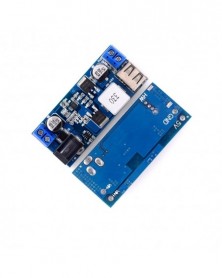
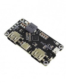
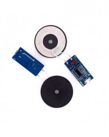
5V 1A vezeték nélküli tápegység töltő modul adó PCBA áramköri kártya barkács tekercs töltéssel 5 W vezeték
161 Ft 374 FtProduct features:
Wireless charging transmitter module, compatible with WPC standard wireless receiver Maximum support 5W charging power Support foreign body detection (FOD) function Low static power consumption and high efficiency Dual LED indicator light can remind the module of the status of power on, charging, charging saturation and foreign body detection (FOD) Limit parameter: Rated working voltage: 5V DC Working temperature: - 20 ° ~ 85 ° Storage temperature: - 40 ° ~ 125 ° Note: the limit operating voltage of the product shall not exceed 5.5v DC Operation instructions: 1. When the power is switched on, the green LED on hw-225 will light up. 2. For the mobile phone with wireless charging function, the coil center of the module hw-225 on the back is placed on the coil of the module to charge the mobile phone (note: the deviation of the position of the mobile phone placed on the coil of the module will affect the charging effect). During the charging process, the red LED on the module hw-225 will light up and the green LED will be put out. 3. After charging, red LED goes out and green LED lights up. 4. The wireless charging module has the function of foreign body detection. When there is a metal foreign body on the transmitting coil of the module, the red light LED and the green light LED will flash. -
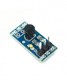
Q36 DS18B20 hőmérsékletmérő modul, hőmérséklet érzékelő modul
243 Ft 564 FtProduct Description
1. On board DS18B20 chip, while leaving a 3P round hole seat, easy to plug DS18B20 chip
2. All the pins of the chip have been led out, with built-in pull-up resistor
3. On board power indicator
4. Board size: 21 (mm) x 10 (mm)
Product wiring:
1. VCC external 3.3v-5v voltage (can be directly connected to 5V or 3.3V MCU)
2. GND external GND
3. Digital output interface of out small board
Delivery list:
DS18B20 temperature measurement module temperature sensor module x 5 -
2db 868MHz szuper kis teljesítményű RF LoRa modul SX1276 chipes távolsági kommunikációs vevő IOT adó SPI IOT
866 Ft 2 014 FtProduct Description
SX1276 Wireless Transceiver Module Lora 868Mhz Modulespread Spectrum Long-Range Wireless Communication LORA/GFSK
Module function
FSK / GFKS technology, LoRa (remote) spread spectrum technology
Half-duplex communication
Super anti-interference (channel rejection ratio: 56db)
High receiver sensitivity -139dbm.
ISM multi-band, do not need to apply the frequency of free use.
Multi-frequency optional, a variety of transmission rates. Can be used in FDMA and FM technology.
Intelligent reset, low-voltage monitoring, wake-up time, low-power mode, sleep mode
Low power receive current: 10-12mA
256-bit FIFO TX / RX
RSSI channel detection function
Transmission Mode: FIFO / Direct Mode (Recommended FIFO Packet Mode)
Configuration: AFC / Wake on Air / Low Power / Carrier Sense / FEC Error Correction / AEC Encryption
Ultra-long-distance transmission as far as 3KM open
Product Pictures -
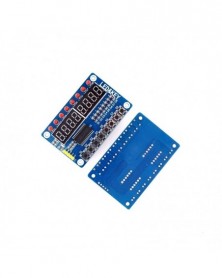
TM1638 modul gombos kijelző AVR Arduino-hoz Új 8 bites digitális LED
131 Ft 305 FtProduct Description:
Weight:28 g
Color: as picture show
Size:75mmx48mm/2.95"x1.89"(inch) (approx)
The rated voltage: DC12V
Voltage range: DC7.0 V-13.6 V
The input power: 0.24 A
The rated speed: 9500 R.P.M
Temperature range:-10.. 70 ° C
Txpect life: 25 ° C L10 when expected life 50000 hours
Bearing structure: free maintenance dual ball bearings
Rotation direction: the wind from stents place eduction, facing the rotor counter-clockwise
The wiring way: red-black signal: blue (blue line, the alarm line speed, it is necessary to pay attention to). Line about 20 cm long
The biggest air volume: 26.8 m? / h
The electric motor protection : overload protection, wrong level protection and stall lock current protection
Minimum wind pressure : 0.. 120 Pa
Noise index : 41.9 dB (A)
Material qualitative material: glass fiber reinforced plastic, PBT shell, PA blades
Function explain : electronic reversing the rotor dc fans, complete electronic directional control components
Including the following resources:
1. 8 key
2. 8 LED common cathode
3. 8 a digital tube common cathode
Use TM1638 digital tube drive chip to drive common cathode LED digital tube
How to connect:
VCC GND 5V power supply, STB CLK DIO MCU I/O port
This module for the chip TM1638, set the above three kinds of single chip microcomputer common peripheral circuit, the biggest characteristic is to simply take microcontroller three IO mouth can drive, scanning display and key scan don't need microcontroller intervention, only need to register to display data related to reading and writing or testing buttons, save MCU resources. Buy the module provides an example program.
Wiring methods :
VCC GND connected 5V supply, STB CLK DIO connected microcontroller IO port. -
Szín: 5V - 5V 12v 4 csatornás relémodul 4 csatornás relévezérlő kártya optocsatoló relé kimenettel 4 utas relémodul
154 Ft 357 FtDescription:
5V Relay Module 4-Channel
This is a 5V 4-Channel Relay interface board.
Be able to control various appliances, and other equipments with large current.
It can be controlled directly by Micro-controller (8051, AVR, PIC, DSP, ARM, ARM, MSP430, TTL logic) .
5V 4-Channel Relay interface board, and each one needs 50-60mA Driver Current.
Equiped with high-current relay, AC250V 10A ; DC30V 10A.
Indication LED's for Relay output status.
Application:
Supports all MCU control.
The industrial field.
PLC control.
Smart home control. -
Szín: 12V - 5V 12v 4 csatornás relémodul 4 csatornás relévezérlő kártya optocsatoló relé kimenettel 4 utas relémodul
154 Ft 357 FtDescription:
5V Relay Module 4-Channel
This is a 5V 4-Channel Relay interface board.
Be able to control various appliances, and other equipments with large current.
It can be controlled directly by Micro-controller (8051, AVR, PIC, DSP, ARM, ARM, MSP430, TTL logic) .
5V 4-Channel Relay interface board, and each one needs 50-60mA Driver Current.
Equiped with high-current relay, AC250V 10A ; DC30V 10A.
Indication LED's for Relay output status.
Application:
Supports all MCU control.
The industrial field.
PLC control.
Smart home control.