- -52%

Micro SD kártya és SDHC (nagy sebességű kártya) Mini TF kártyaolvasó modul adapter SPI interfészek szintátalakító
Micro SD kártya és SDHC (nagy sebességű kártya) Mini TF kártyaolvasó modul adapter SPI interfészek szintátalakító
81 Ft
52% megtakarítás
168 Ft
Nincs adó
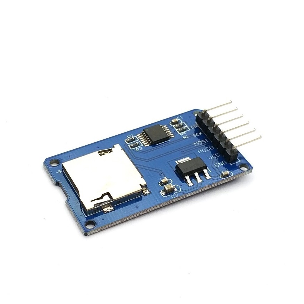
Micro SD Card & SDHC(high-speed card) Mini TF Card Reader Module Adapter SPI Interfaces with Level Converter Chip for uno
Description:
The module (microSD card adapter) is a micro SD card reading and writing module, the file system and SPI interface driver, SCM system can complete the microSD card file to read and write. Arduino users can directly use the IDE Arduino built-in SD card program library to complete the initialization of the card and read and write
Module features are as follows:
1 support SD Micro card, SDHC Micro card (high speed card)
2 board level conversion circuit, that is, the interface level can be 5V or 3.3V
3 power supply for the 4.5V~5.5V, plate load 3.3V voltage regulator circuit
4 coMmunication interface for the standard SPI interface
5.4 M2 screw positioning holes, easy to install
Interface parameter:
project
minimum value
Typical value
Maximum value
Company
Power supply voltage VCC
4.5
5
5.5
V
Electric current
0.2
80
200
MA
Interface level
3.3 or 5
V
Support card type
Micro SD card (<=2G), SDHC Mirco card (<=32G)
-
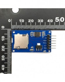
size
42X24X12
mm
weight
5
g
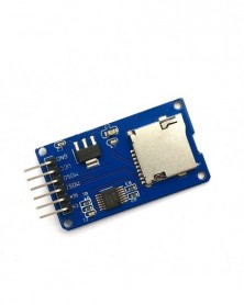
Interface description:
Mirco SD card module interface as shown below:
control interface: a total of 6 (GND and VCC, miso, MoSi, SCK, CS) pin and GND for VCC power supply, miso, MoSi, SCK for the SPI bus CS is the chip select signal feet;
3.3VVoltage stabilizing circuitLDO voltage regulator output of the 3.3V for the level conversion chip, Micro SD card power supply;
Level conversion circuitMicro SD card into the direction of the signal is converted into MicroSD, 3.3V card to control the direction of the interface MISO signal is converted into 3.3V, the general AVR microcontroller system can read the signal;
Micro SDcassetteIs self spring type connector, convenient card plug.
Locating hole4 M2 screw positioning holes, the size of 2.2mm, so that the module is easy to install and locate, realize the combination between modules;
Usage method:
1 Arduino compatible motherboard Catduino (not familiar with the open source hardware can be understood as Atmega328P microcontroller development board) and a USB Mini line;
1 Micro SD card module;
1 Samsung Micro 2G SD card;
1ArduinoInterface expansion board shield Base(internal links);
The 6 mother to the DuPont line, used to connect the module control interface and Shield Base on the lead out of the SPI interface;
Experimental procedure
1 Shield Base directly to the Catduino board, to ensure that the Micro SD card has been formatted as FAT16 or FAT32 format, and plug it into the Micro SD card module.
2 with the mother of the 6 mother to the DuPont line Micro SD card module and Shield SPI Base interface to connect, as shown in the following table
Shield Base
Connecting line
Micro SD card module
GND
The black line
GND
VCC
Red thread
VCC
MISO
The yellow line
MISO
MOSI
The white line
MOSI
SCK
The green line
SCK
D5
blue line
CS
3 with USB Mini will be connected to Catduino, if it is the first time to use the motherboard, its USB to the serial port driver can be found under the IDE drivers USB Arduino Drivers.
4 Micro SD card reader to write the relevant procedures can be used to bring the IDE Arduino program, the directory is
..Arduino-1.0librariesSD. Re open the Arduino ide. Click on the toolbar of the open button, open CardInfo the SD in the routines, as shown in the figure below, need to pay attention to is chip select signal pins should be changed into a real connection to the chip select pin of the module. In this experiment, select the D10, as shown in figure in a red box.
Select the serial port, the board name, click the burn button, you can burn. The routine shows how to read the Micro SD card information, including the card type, file system type, storage capacity, and also lists the file card in the file name. Click Monitor Serial to view.
In the SD library, there are other routines, users can experiment with more and more.
*Version information *
version number
describe
Release date
V0.9b
Initial public release
2013.07.14
V1.0
1.Micro SD card at the entrance of PCB into the concave, the card is more convenient
2 optimize the layout of layout PCB
2013.09.08
Packing list:
1 Micro SD card
Description:
The module (microSD card adapter) is a micro SD card reading and writing module, the file system and SPI interface driver, SCM system can complete the microSD card file to read and write. Arduino users can directly use the IDE Arduino built-in SD card program library to complete the initialization of the card and read and write
Module features are as follows:
1 support SD Micro card, SDHC Micro card (high speed card)
2 board level conversion circuit, that is, the interface level can be 5V or 3.3V
3 power supply for the 4.5V~5.5V, plate load 3.3V voltage regulator circuit
4 coMmunication interface for the standard SPI interface
5.4 M2 screw positioning holes, easy to install
Interface parameter:
project
minimum value
Typical value
Maximum value
Company
Power supply voltage VCC
4.5
5
5.5
V
Electric current
0.2
80
200
MA
Interface level
3.3 or 5
V
Support card type
Micro SD card (<=2G), SDHC Mirco card (<=32G)
-
size
42X24X12
mm
weight
5
g
Interface description:
Mirco SD card module interface as shown below:
control interface: a total of 6 (GND and VCC, miso, MoSi, SCK, CS) pin and GND for VCC power supply, miso, MoSi, SCK for the SPI bus CS is the chip select signal feet;
3.3VVoltage stabilizing circuitLDO voltage regulator output of the 3.3V for the level conversion chip, Micro SD card power supply;
Level conversion circuitMicro SD card into the direction of the signal is converted into MicroSD, 3.3V card to control the direction of the interface MISO signal is converted into 3.3V, the general AVR microcontroller system can read the signal;
Micro SDcassetteIs self spring type connector, convenient card plug.
Locating hole4 M2 screw positioning holes, the size of 2.2mm, so that the module is easy to install and locate, realize the combination between modules;
Usage method:
1 Arduino compatible motherboard Catduino (not familiar with the open source hardware can be understood as Atmega328P microcontroller development board) and a USB Mini line;
1 Micro SD card module;
1 Samsung Micro 2G SD card;
1ArduinoInterface expansion board shield Base(internal links);
The 6 mother to the DuPont line, used to connect the module control interface and Shield Base on the lead out of the SPI interface;
Experimental procedure
1 Shield Base directly to the Catduino board, to ensure that the Micro SD card has been formatted as FAT16 or FAT32 format, and plug it into the Micro SD card module.
2 with the mother of the 6 mother to the DuPont line Micro SD card module and Shield SPI Base interface to connect, as shown in the following table
Shield Base
Connecting line
Micro SD card module
GND
The black line
GND
VCC
Red thread
VCC
MISO
The yellow line
MISO
MOSI
The white line
MOSI
SCK
The green line
SCK
D5
blue line
CS
3 with USB Mini will be connected to Catduino, if it is the first time to use the motherboard, its USB to the serial port driver can be found under the IDE drivers USB Arduino Drivers.
4 Micro SD card reader to write the relevant procedures can be used to bring the IDE Arduino program, the directory is
..Arduino-1.0librariesSD. Re open the Arduino ide. Click on the toolbar of the open button, open CardInfo the SD in the routines, as shown in the figure below, need to pay attention to is chip select signal pins should be changed into a real connection to the chip select pin of the module. In this experiment, select the D10, as shown in figure in a red box.
Select the serial port, the board name, click the burn button, you can burn. The routine shows how to read the Micro SD card information, including the card type, file system type, storage capacity, and also lists the file card in the file name. Click Monitor Serial to view.
In the SD library, there are other routines, users can experiment with more and more.
*Version information *
version number
describe
Release date
V0.9b
Initial public release
2013.07.14
V1.0
1.Micro SD card at the entrance of PCB into the concave, the card is more convenient
2 optimize the layout of layout PCB
2013.09.08
Packing list:
1 Micro SD card

Szállításii feltételek

Biztonsági feltételek

Visszaküldési feltételek