- -52%
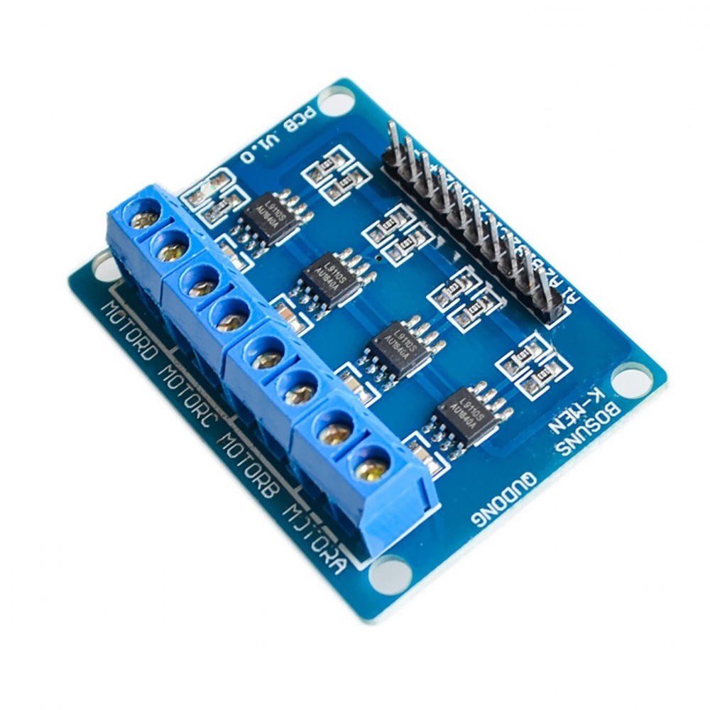

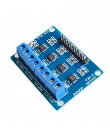

L9110S 4-utas hajtás DC motor meghajtó lemez motor meghajtó modul 4 utas intelligens autó
L9110S 4-utas hajtás DC motor meghajtó lemez motor meghajtó modul 4 utas intelligens autó
105 Ft
52% megtakarítás
218 Ft
Nincs adó
-2
/
 2
A Megtakarítás az Üzletben is Beváltható
2
A Megtakarítás az Üzletben is Beváltható
Students, teachers, traders, factories, electronics enthusiasts, welcome to our shop Pi quantity procurement, Pi hair price please contact customer service, thank you for your support.
Module Description
1 Motor drive module itself has its own four-channel L9110S chip.
2 Module power supply voltage: 2.5-12V
3 suitable motor range: motor working voltage between 2.5V-12V, large working current 0.8A, the current on the market smart car voltage and current are within this range
4 can drive 4 DC motors at the same time, or 2 4-wire 2-phase stepper motors.
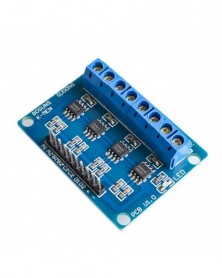
Module interface description
[10P black bent row needle description]
1 A1 Connects to the IO port of the single-chip microcomputer
2 A2 Connects to the I/O port of the microcontroller
3 B1 Connects to the IO port of the single chip microcomputer
4 B2 Connects to the IO port of the single chip microcomputer
5 C1 Connects to the I/O port of the single chip microcomputer
6 C2 Connects to the IO port of the microcontroller
7 D1 Connects to the I/O port of the microcontroller
8 D2 Connects to the I/O port of the microcontroller
9 External 2.5V-12V voltage
10 - External GND
Description of 8P PCB wiring terminal
1 MOTORA is connected with dc motor 2 pins, no direction
2 MOTORB is connected with two pins of DC motor, no direction
3 MOTORC is connected with dc motor 2 pins, no direction
4 MOTORD is connected to dc motor with two pins, no direction
Module instructions
When the VCC is connected, the GND power indicator is on
A1 input high level, A2 input low level, MOTORA motor positive;
A1 input low level, A2 input high level, MOTORA motor reverse;
B1 input high level, B2 input low level, MOTORB motor positive;
B1 input low level, B2 input high level, MOTORB motor inversion;
C1 input high level, C2 input low level, MOTORC motor positive;
C1 input low level, C2 input high level, MOTORC motor reverse;
D1 input high level, D2 input low level, MOTORD motor positive;
D1 input low level, D2 input high level, MOTORD motor reverse;
Module Description
1 Motor drive module itself has its own four-channel L9110S chip.
2 Module power supply voltage: 2.5-12V
3 suitable motor range: motor working voltage between 2.5V-12V, large working current 0.8A, the current on the market smart car voltage and current are within this range
4 can drive 4 DC motors at the same time, or 2 4-wire 2-phase stepper motors.
Module interface description
[10P black bent row needle description]
1 A1 Connects to the IO port of the single-chip microcomputer
2 A2 Connects to the I/O port of the microcontroller
3 B1 Connects to the IO port of the single chip microcomputer
4 B2 Connects to the IO port of the single chip microcomputer
5 C1 Connects to the I/O port of the single chip microcomputer
6 C2 Connects to the IO port of the microcontroller
7 D1 Connects to the I/O port of the microcontroller
8 D2 Connects to the I/O port of the microcontroller
9 External 2.5V-12V voltage
10 - External GND
Description of 8P PCB wiring terminal
1 MOTORA is connected with dc motor 2 pins, no direction
2 MOTORB is connected with two pins of DC motor, no direction
3 MOTORC is connected with dc motor 2 pins, no direction
4 MOTORD is connected to dc motor with two pins, no direction
Module instructions
When the VCC is connected, the GND power indicator is on
A1 input high level, A2 input low level, MOTORA motor positive;
A1 input low level, A2 input high level, MOTORA motor reverse;
B1 input high level, B2 input low level, MOTORB motor positive;
B1 input low level, B2 input high level, MOTORB motor inversion;
C1 input high level, C2 input low level, MOTORC motor positive;
C1 input low level, C2 input high level, MOTORC motor reverse;
D1 input high level, D2 input low level, MOTORD motor positive;
D1 input low level, D2 input high level, MOTORD motor reverse;

Szállításii feltételek

Biztonsági feltételek

Visszaküldési feltételek