- -52%
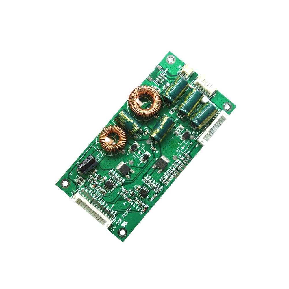
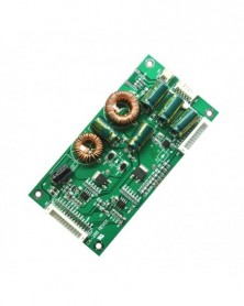
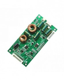

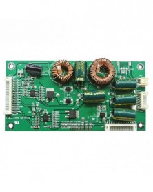
CA-288 univerzális 26-55 hüvelykes LED LCD TV háttérvilágítású illesztőprogram panel TV erősítő lemez állandó
CA-288 univerzális 26-55 hüvelykes LED LCD TV háttérvilágítású illesztőprogram panel TV erősítő lemez állandó
299 Ft
52% megtakarítás
622 Ft
Nincs adó
-1
/
 1
A Megtakarítás az Üzletben is Beváltható
1
A Megtakarítás az Üzletben is Beváltható
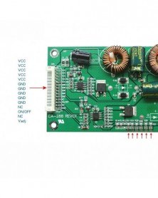
vin: 19-45V DC
vout: 60-165V automatic adaptation
Constant current output: 200mA
The current can be adjusted according to actual needs
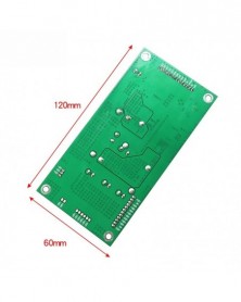
Structure size: length 120mm, width 60mm, height 11mm
Purpose: used for 26 inch -55 inch LED TV monitor, voltage exceeding 100V and below 165V
Input voltage range: 19-45V DC Output voltage range: 60-165V DC
Output current: 10MA-1000MA can be set
Before you buy, you should understand the following important information:
1. The working voltage of the light bar must be any voltage between 60V-165. It cannot be lower than 60V. If it is lower than 60V, you can choose to buy other products in our store. It cannot be higher than 165V. The design limit working voltage of this product should not be higher than 165V. If this voltage is exceeded, the screen will be dark or the lamp will flicker. This product only has a constant current, not a constant voltage. The voltage will be automatically adjusted to the corresponding voltage according to the required voltage of the light bar, so you don't need to worry about how many volts are measured when there is no load.
2. In view of the fact that many buyers have bought and modified, and the parameters of the machine that need to be modified are unknown, so here is a statement: The quality and performance of the products sold in this shop are absolutely correct, but there is no guarantee that the goods you buy are The fact that it will be able to successfully light up. There are many reasons that may lead to non-matching. Voltage, power supply, connection, structure, etc. may all cause mismatch.
3. Conventional parameters: 60V-160V 200MA@ 24VIN
4. Problems that may be encountered when lighting up correctly:
1. The brightness is not enough, and the screen is obviously darker than the original board. At this time, start from two aspects. First, after connecting the dimming foot, try to use the remote control to adjust the brightness to see if it can be solved. If it can't be solved, test the actual The voltage of the pin, [Note: The brightness of my product is 0V, and the brightness is dark when the voltage is high. 】If the voltage range of the analog voltage mode is between 0V-5V or 0V-3.3V, if the voltage is always at a high voltage and cannot be reduced, this should be adjusted. If it is a PWM signal, the voltage is stable at 3.3V. At this time, if it is turned on and still does not meet the requirements, the second solution must be implemented. Second, adjust the resistance on the board to increase the current to meet the requirements.
5. In view of the fact that many buyers do not understand the topology of the LED driver board, the lack of understanding of its working principle directly leads to the consequences of not being able to use it correctly! Hereby, our company briefly introduces the current popular topology schemes. There are mainly three commonly used topologies: boost, buck, and boost-buck.
1. Boost topology means boost type. Interpretation: When using a constant current board with this type of solution, the load voltage [Vout] must be higher than the power input voltage [Vin], and the ratio must be greater than 1:1.5, that is, if the input voltage is 12V, the LED string voltage must When the voltage is above 18V, the LED booster board can work normally. If the voltage of the LED string is slightly higher than VIN or lower than VIN, the situation will be that the LED lights up when the machine is powered on, and the driver board cannot be switched or dimmed. Consequences of control. 2. The advantage of the Boost scheme lies in its simple structure and high efficiency. The disadvantage is that the boost ratio is limited, and the general boost ratio is 2-4 times. When it exceeds 6 times, the switching loss increases sharply, the temperature of the switching device rises sharply, and the system stability deteriorates.
2. Buck topology means buck type. Interpretation: When the constant current board adopts this kind of solution, the load voltage [Vout] must be lower than the power input voltage [VIN], that is: if the input voltage is 12V, the voltage of the light bar should be lower than 12V, when it is 24VIN It must be lower than 24V. If the voltage of the LED strip is higher than VIN, it cannot be driven to light up. The advantage of the Buck scheme lies in its simple structure and slightly higher efficiency than the Boost scheme. The disadvantage is that only a small number of LEDs can be connected in series. When the power is large, there are too many groups in parallel, which is disadvantageous for the PCB layout of the LED backlight module with compact space.
3. Boost-buck topology means boost-buck type. Interpretation: This type of program also has the function of step-up and step-down. It has the working modes of the first two schemes. But the disadvantage is that the efficiency is low and it is not suitable for high power occasions.
The most widely used in the industry is the Boost solution, followed by Buck, and boost-buck is smaller.
vout: 60-165V automatic adaptation
Constant current output: 200mA
The current can be adjusted according to actual needs
Structure size: length 120mm, width 60mm, height 11mm
Purpose: used for 26 inch -55 inch LED TV monitor, voltage exceeding 100V and below 165V
Input voltage range: 19-45V DC Output voltage range: 60-165V DC
Output current: 10MA-1000MA can be set
Before you buy, you should understand the following important information:
1. The working voltage of the light bar must be any voltage between 60V-165. It cannot be lower than 60V. If it is lower than 60V, you can choose to buy other products in our store. It cannot be higher than 165V. The design limit working voltage of this product should not be higher than 165V. If this voltage is exceeded, the screen will be dark or the lamp will flicker. This product only has a constant current, not a constant voltage. The voltage will be automatically adjusted to the corresponding voltage according to the required voltage of the light bar, so you don't need to worry about how many volts are measured when there is no load.
2. In view of the fact that many buyers have bought and modified, and the parameters of the machine that need to be modified are unknown, so here is a statement: The quality and performance of the products sold in this shop are absolutely correct, but there is no guarantee that the goods you buy are The fact that it will be able to successfully light up. There are many reasons that may lead to non-matching. Voltage, power supply, connection, structure, etc. may all cause mismatch.
3. Conventional parameters: 60V-160V 200MA@ 24VIN
4. Problems that may be encountered when lighting up correctly:
1. The brightness is not enough, and the screen is obviously darker than the original board. At this time, start from two aspects. First, after connecting the dimming foot, try to use the remote control to adjust the brightness to see if it can be solved. If it can't be solved, test the actual The voltage of the pin, [Note: The brightness of my product is 0V, and the brightness is dark when the voltage is high. 】If the voltage range of the analog voltage mode is between 0V-5V or 0V-3.3V, if the voltage is always at a high voltage and cannot be reduced, this should be adjusted. If it is a PWM signal, the voltage is stable at 3.3V. At this time, if it is turned on and still does not meet the requirements, the second solution must be implemented. Second, adjust the resistance on the board to increase the current to meet the requirements.
5. In view of the fact that many buyers do not understand the topology of the LED driver board, the lack of understanding of its working principle directly leads to the consequences of not being able to use it correctly! Hereby, our company briefly introduces the current popular topology schemes. There are mainly three commonly used topologies: boost, buck, and boost-buck.
1. Boost topology means boost type. Interpretation: When using a constant current board with this type of solution, the load voltage [Vout] must be higher than the power input voltage [Vin], and the ratio must be greater than 1:1.5, that is, if the input voltage is 12V, the LED string voltage must When the voltage is above 18V, the LED booster board can work normally. If the voltage of the LED string is slightly higher than VIN or lower than VIN, the situation will be that the LED lights up when the machine is powered on, and the driver board cannot be switched or dimmed. Consequences of control. 2. The advantage of the Boost scheme lies in its simple structure and high efficiency. The disadvantage is that the boost ratio is limited, and the general boost ratio is 2-4 times. When it exceeds 6 times, the switching loss increases sharply, the temperature of the switching device rises sharply, and the system stability deteriorates.
2. Buck topology means buck type. Interpretation: When the constant current board adopts this kind of solution, the load voltage [Vout] must be lower than the power input voltage [VIN], that is: if the input voltage is 12V, the voltage of the light bar should be lower than 12V, when it is 24VIN It must be lower than 24V. If the voltage of the LED strip is higher than VIN, it cannot be driven to light up. The advantage of the Buck scheme lies in its simple structure and slightly higher efficiency than the Boost scheme. The disadvantage is that only a small number of LEDs can be connected in series. When the power is large, there are too many groups in parallel, which is disadvantageous for the PCB layout of the LED backlight module with compact space.
3. Boost-buck topology means boost-buck type. Interpretation: This type of program also has the function of step-up and step-down. It has the working modes of the first two schemes. But the disadvantage is that the efficiency is low and it is not suitable for high power occasions.
The most widely used in the industry is the Boost solution, followed by Buck, and boost-buck is smaller.

Szállításii feltételek

Biztonsági feltételek

Visszaküldési feltételek