- -50%

ALTERA MAX II EPM570 CPLD alaplap és USB Blaster FPGA programozó letöltő JTAG PLD logikai fejlesztőkészlet mátrix LED LCD
ALTERA MAX II EPM570 CPLD alaplap és USB Blaster FPGA programozó letöltő JTAG PLD logikai fejlesztőkészlet mátrix LED LCD
5 262 Ft
50% megtakarítás
10 523 Ft
Nincs adó
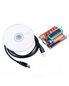
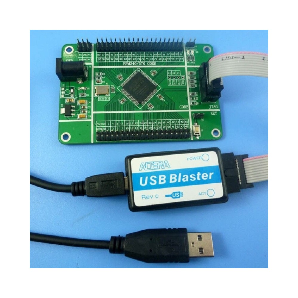
Product Name:ALTERA MAX II EPM570 CPLD Core Board & USB Blaster FPGA Programmer Downloader JTAG PLD Logic Development kit for Matrix LED LCD
Module No#: RT319
Packing list:
1 PCS EPM570 core board
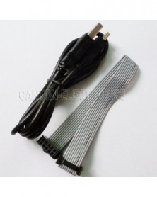
1 PCS Altera USB Blaster #with USB wire and 10 pin JTAG wire#
Description:
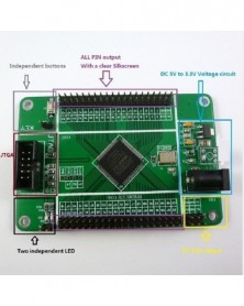
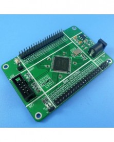
EPM570 Board Description:
Onboard EPM570T100C5N chip, LEs and Equivalent Macrocells More than doubled EPM240
50Mhz Active crystal
All pins from CPLD are Labelled and available onboard
Altera Official standards JTAG Interface
Two 5V 3#3V output to provide power for the peripheral
A Independent button for test core board
Two independent LED lights for test core board
Size : 9cm X 6cm #9:6 is Golden ratio ^_^#
Diagram : Please contact me on ebay message for diagram after your order !
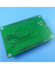
PCB Board 3D View:
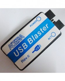
Altera USB Blaster:
Feature :
1.Stably support SignalTap II embedded logic analyzer function ,no mistake while crawlling data;
2. Fully support all Altera products such as :
CPLD: MAX3000, MAX7000, MAX9000 and MAXII
FPGA: Stratix, StratixII, StratxIII, Cyclone, CycloneII, CycloneIII, ACEX1K, APEX20K and FLEX10K etc#
Active serial configuration device: EPCS1, EPCS4, EPCS16, EPCS64 etc#
Enhanced configuration devices: EPC1, EPC4#
3# Supports 3 download mode: AS, PS and JTAG;
4. Support and Nios II embedded soft core processor communication and debugging, Rev.C latest version Hardware. Support jtag_uart;
5. Speed: 6 times faster than parallel port download cable ByteBlasterII;
6. Easy to use: MiniUSB interface, easy connection, two status indicator makes debugging more comfortable.
7. Fully compatible with ALTERA USB Blaster, functionality and performance are the same as ALTERA original download cable.
8: Voltage : 1.5~5V JTAG IO Voltage .
System configuration:
1, Windows XP, Windows Vista, Windows7 ,USB interface;
2, Quartus II version 4.0 or newer version;
This programmer uses standard 10-Pin ICD10 interface, the Pin assignment is shown as followed:
10-Pin interface #the triangle mark on cable "" means 1st pin#:
Module No#: RT319
Packing list:
1 PCS EPM570 core board
1 PCS Altera USB Blaster #with USB wire and 10 pin JTAG wire#
Description:
EPM570 Board Description:
Onboard EPM570T100C5N chip, LEs and Equivalent Macrocells More than doubled EPM240
50Mhz Active crystal
All pins from CPLD are Labelled and available onboard
Altera Official standards JTAG Interface
Two 5V 3#3V output to provide power for the peripheral
A Independent button for test core board
Two independent LED lights for test core board
Size : 9cm X 6cm #9:6 is Golden ratio ^_^#
Diagram : Please contact me on ebay message for diagram after your order !
PCB Board 3D View:
Altera USB Blaster:
Feature :
1.Stably support SignalTap II embedded logic analyzer function ,no mistake while crawlling data;
2. Fully support all Altera products such as :
CPLD: MAX3000, MAX7000, MAX9000 and MAXII
FPGA: Stratix, StratixII, StratxIII, Cyclone, CycloneII, CycloneIII, ACEX1K, APEX20K and FLEX10K etc#
Active serial configuration device: EPCS1, EPCS4, EPCS16, EPCS64 etc#
Enhanced configuration devices: EPC1, EPC4#
3# Supports 3 download mode: AS, PS and JTAG;
4. Support and Nios II embedded soft core processor communication and debugging, Rev.C latest version Hardware. Support jtag_uart;
5. Speed: 6 times faster than parallel port download cable ByteBlasterII;
6. Easy to use: MiniUSB interface, easy connection, two status indicator makes debugging more comfortable.
7. Fully compatible with ALTERA USB Blaster, functionality and performance are the same as ALTERA original download cable.
8: Voltage : 1.5~5V JTAG IO Voltage .
System configuration:
1, Windows XP, Windows Vista, Windows7 ,USB interface;
2, Quartus II version 4.0 or newer version;
This programmer uses standard 10-Pin ICD10 interface, the Pin assignment is shown as followed:
10-Pin interface #the triangle mark on cable "" means 1st pin#:

Biztonsági feltételek

Szállításii feltételek

Visszaküldési feltételek