- -52%


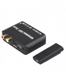
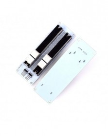
DC 9V 12V 4 csatornás RS232 relémodul soros port UART kártya Smart PLC csere USB Wifi hálózat Ethernet időrelé
DC 9V 12V 4 csatornás RS232 relémodul soros port UART kártya Smart PLC csere USB Wifi hálózat Ethernet időrelé
1 167 Ft
52% megtakarítás
2 432 Ft
Nincs adó
Product Name:
DC 9V12V 4 Channel RS232 Relay Module Serial port UART Board replace Smart PLC USB Wifi Bluetooth Network Ethernet time Relay
Package inlcuded:
1 x DC 9V 12V 2 Channel RS232 Relay Board
1 x DC 5V 2 Channel Expansion Relay Board
4 x DuPont wire(Random Color)
Description:
4 Channel Relay Board : 2 Channel RS232 Relay Board 2 Channel Expansion Relay Board;
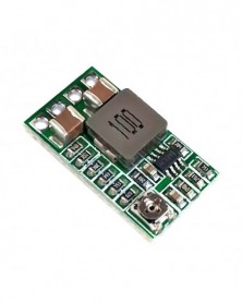
2 Channel RS232 Relay Board 2 Power input: DC 9-12V.
2 Channel Expansion Relay Board : Power supply DC 5V
PC Serial ports RS232 Control Relay;
Power indicator : LED lights;
Output indication : relay output with LED indicators,easy to see working status of the relay;
Communication protocol: UART protocol communication, baud rate 9600kpbs, 8 data bits, one stop bit, no parity. Each data frame contains eight bytes. Two-way data transmission.
Baud rate 9600kbps, 8 data bits, one stop bit, no parity. Each data frame contains eight bytes.
PCB Size : RS232 Relay Board 71 x 47mm; Expansion Relay Board 52 x 38mm
1 Control commands:
1. Reading status(reading the satus of the relay (on/off))
0x55 0x56 0x00 0x00 0x00 0x00 0x00 0xAB
2. Relay open (issue this command ,Relay open,COM connect to NO)
Channel 1 : 0x55 0x56 0x00 0x00 0x00 0x01 0x01 0xAD
Channel 2 : 0x55 0x56 0x00 0x00 0x00 0x02 0x01 0xAE
Channel 3 : 0x55 0x56 0x00 0x00 0x00 0x03 0x01 0xAF
Channel 4 : 0x55 0x56 0x00 0x00 0x00 0x04 0x01 0xB0
3. Relay close (issue this command ,Relay close ,COM disconnect NO,and COM connect to NC)
Channel 1 : 0x55 0x56 0x00 0x00 0x00 0x01 0x02 0xAE
Channel 2 : 0x55 0x56 0x00 0x00 0x00 0x02 0x02 0xAF
Channel 3 : 0x55 0x56 0x00 0x00 0x00 0x03 0x02 0xB0
Channel 4 : 0x55 0x56 0x00 0x00 0x00 0x04 0x02 0xB1
4. Relay toggle(Relay status reversal,if COM connect to NO,this commands will Disconnect
COM to NO and Reverse COM connect to NC,and vice versa)
Channel 1 : 0x55 0x56 0x00 0x00 0x00 0x01 0x03 0xAF
Channel 2 : 0x55 0x56 0x00 0x00 0x00 0x02 0x03 0xB0
Channel 3 : 0x55 0x56 0x00 0x00 0x00 0x03 0x03 0xB1
Channel 4 : 0x55 0x56 0x00 0x00 0x00 0x04 0x03 0xB2
5. Relay momentary(Relay COM connect to NO,disconnect after 200MS)
Channel 1 : 0x55 0x56 0x00 0x00 0x00 0x01 0x04 0xB0
Channel 2 : 0x55 0x56 0x00 0x00 0x00 0x02 0x04 0xB1
Channel 3 : 0x55 0x56 0x00 0x00 0x00 0x03 0x04 0xB2
Channel 4 : 0x55 0x56 0x00 0x00 0x00 0x04 0x04 0xB3
Once issue a command,will have a return fame, 7th byte of return fame mean the satus of realy
2 return commands:
1.Return relay open(return this command,mean COM connect to NO)
Channel 1 : 0x33 0x3C 0x00 0x00 0x00 0x01 0x01 0x71
Channel 2 : 0x33 0x3C 0x00 0x00 0x00 0x02 0x01 0x72
Channel 3 : 0x33 0x3C 0x00 0x00 0x00 0x03 0x01 0x73
Channel 4 : 0x33 0x3C 0x00 0x00 0x00 0x04 0x01 0x74
2.Return relay close(return this command,mean COM disconnect NO,and COM connect to NC)
Channel 1 : 0x33 0x3C 0x00 0x00 0x00 0x01 0x02 0x72
Channel 2 : 0x33 0x3C 0x00 0x00 0x00 0x02 0x02 0x73
Channel 3 : 0x33 0x3C 0x00 0x00 0x00 0x03 0x02 0x74
Channel 4 : 0x33 0x3C 0x00 0x00 0x00 0x04 0x02 0x75
Instruction manual Please ask us after the purchase
Application
Remote control, remote measurement system;
Wireless meter
;
Smart Home,Home Automation ,Wiser Home;
Access control
;
Identification system
;
Data collection;
IT household appliance
;
Intelligence household appliance;
Baby monitoring system;
Home Appliances;
Reversible Motor Control;
Typial application :
1 DC 12V control circuit,Wiring diagram below. ''LOAD'' may be LED lights, fans, motors and other DC 12V equipment
2 DC 1-48V OR AC 85-265V control circuit,Wiring diagram below(Note:If not DC 12V load, need another DC 12V power supply). ''LOAD'' may be LED lights, fans, motors and other DC AC equipmentipment
Test Software:(Only support win xp (32/62) win 7 (32/62) Operating System)

Szállításii feltételek

Biztonsági feltételek

Visszaküldési feltételek