- -52%
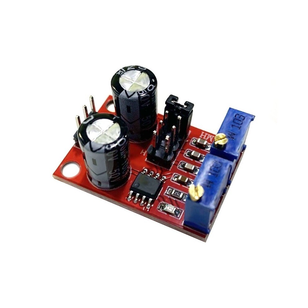
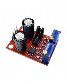

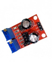
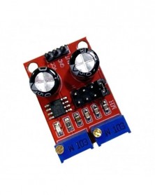
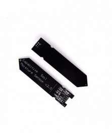
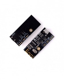
NE555 impulzusfrekvenciás munkaciklus állítható modul négyszögletes téglalap hullám jelgenerátor léptetőmotoros
NE555 impulzusfrekvenciás munkaciklus állítható modul négyszögletes téglalap hullám jelgenerátor léptetőmotoros
101 Ft
52% megtakarítás
211 Ft
Nincs adó
Data download link:
https://drive.google.com/file/d/15F-QEphoQjYLnPql8yqYJF1IGbM6U452/view?usp=sharing
1. The scope of application of this module:
1. Used as a square wave signal generator to generate square wave signals for experimental development.
2. It is used to generate square wave signal to drive the stepper motor driver.
3. Generate adjustable pulses for MCU use.
4. Generate adjustable pulses to control related circuits.
2. Brief description:
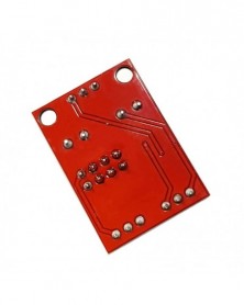
1. Size: 3.1CM*2.2CM
1. Main chip: NE555;
2. Input voltage: 5V-15VDC. When powered by 5V, the output current can be around 15MA; when powered by 12V, the output current can be around 35MA;
3. Input current: ≥100MA
4. Output amplitude: 4.2V V-PP to 11.4V V-PP. (depending on the input voltage, the output amplitude will be different)
5. Output current: ≥15MA (5V power supply, when V-PP is greater than 50% ), ≥35MA (12V power supply, when V-PP is greater than 50% )
Three advantages:
1. The output has LED indication, and it is directly clear whether there is any output (the amount of LED is at low level, the LED is off at high level, and the LED flashes when the frequency is relatively low);
2. The output frequency range is optional, making the output frequency more continuously adjustable;
Low frequency file: 1Hz~50Hz
IF file: 50Hz~1kHz
Medium and high frequency range: 1KHz~10kHz
High frequency file: 10kHz~200kHz
3. The output duty cycle can be fine-tuned. The duty cycle and frequency are not adjustable separately. Adjusting the duty cycle will change the frequency;
4. The output frequency is adjustable;
Period T=0.7(RA 2RB)C
RA and RB are adjustable from 0 to 10K;
C=0.001UF at low frequency;
C=0.1UF at intermediate frequency;
Medium and high frequency range C=1UF;
C=100UF at high frequency, so buyers can calculate the frequency of the waveform by themselves
https://drive.google.com/file/d/15F-QEphoQjYLnPql8yqYJF1IGbM6U452/view?usp=sharing
1. The scope of application of this module:
1. Used as a square wave signal generator to generate square wave signals for experimental development.
2. It is used to generate square wave signal to drive the stepper motor driver.
3. Generate adjustable pulses for MCU use.
4. Generate adjustable pulses to control related circuits.
2. Brief description:
1. Size: 3.1CM*2.2CM
1. Main chip: NE555;
2. Input voltage: 5V-15VDC. When powered by 5V, the output current can be around 15MA; when powered by 12V, the output current can be around 35MA;
3. Input current: ≥100MA
4. Output amplitude: 4.2V V-PP to 11.4V V-PP. (depending on the input voltage, the output amplitude will be different)
5. Output current: ≥15MA (5V power supply, when V-PP is greater than 50% ), ≥35MA (12V power supply, when V-PP is greater than 50% )
Three advantages:
1. The output has LED indication, and it is directly clear whether there is any output (the amount of LED is at low level, the LED is off at high level, and the LED flashes when the frequency is relatively low);
2. The output frequency range is optional, making the output frequency more continuously adjustable;
Low frequency file: 1Hz~50Hz
IF file: 50Hz~1kHz
Medium and high frequency range: 1KHz~10kHz
High frequency file: 10kHz~200kHz
3. The output duty cycle can be fine-tuned. The duty cycle and frequency are not adjustable separately. Adjusting the duty cycle will change the frequency;
4. The output frequency is adjustable;
Period T=0.7(RA 2RB)C
RA and RB are adjustable from 0 to 10K;
C=0.001UF at low frequency;
C=0.1UF at intermediate frequency;
Medium and high frequency range C=1UF;
C=100UF at high frequency, so buyers can calculate the frequency of the waveform by themselves

Szállításii feltételek

Biztonsági feltételek

Visszaküldési feltételek