- -51%
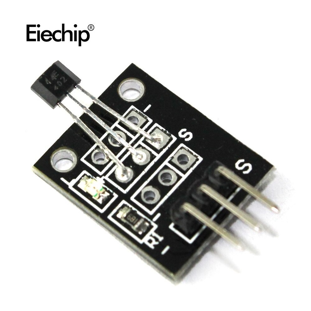
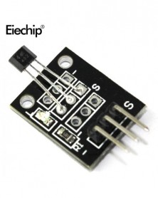
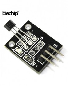
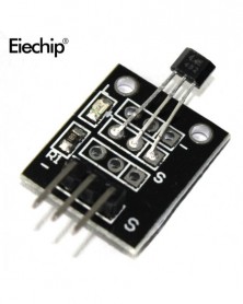
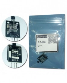
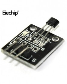
KY-003 Szabványos csarnokáram-érzékelő modul Mágneses érzékelő modul Arduino AVR Smart CarsPIC KY 003-hoz
KY-003 Szabványos csarnokáram-érzékelő modul Mágneses érzékelő modul Arduino AVR Smart CarsPIC KY 003-hoz
62 Ft
51% megtakarítás
126 Ft
Nincs adó
s
Hall Switch Integrated Circuit Using hall Effect Principle
USES The Semiconductor Integrated Technology Manufacturing Magnetic Susceptibility of the Circuit
Its Input For the Magnetic Induction Intensity, the Output is a Digital Voltage Signa
1. Non-Contact Switch
2. Hall Switch Integrated Circuit Using hall Effect Principle,
3. USES The Semiconductor Integrated Technology Manufacturing Magnetic Susceptibility of the Circuit,
4. It is by the Voltage Regulator, Hall Voltage Generator, Differential Amplifier, Schmidt Triggers, Temperature Compensation and the Open Collector Output Stage Circuit Composed of Magnetic Sensitive Sensor Circuit
5. Its Input For the Magnetic Induction Intensity, the Output is a Digital Voltage Signal
Description :
Working voltage:4.5V-24V
Series 3144, hall switch integrated circuit using hall effect principle, USES the semiconductor integrated technology manufacturing magnetic susceptibility of the circuit, it is by the voltage regulator, hall voltage generator, differential amplifier, schmidt triggers, temperature compensation and the open collector output stage circuit composed of magnetic sensitive sensor circuit, its input for the magnetic induction intensity, the output is a digital voltage signal.
Hall magnetic sensor module and a digital 13 interface with LED build a simple circuit, to produce a magnetic flasher .Use digital 13 interface with the LED, the Hall magnetic sensor connected to the force plate number 3 for ARDUINO interface. When the Hall magnetic sensor to a magnetic field signal , LED lights on, versa lights off.
Reference Program:
int Led=13;// Definition LED Interface
int SENSOR=3;// Define the Hall magnetic sensor interface
int val;// Defines a numeric variable val
void setup()
{
pinMode(Led,OUTPUT);// Definition LED as output interface
pinMode SENSOR,INPUT);// Defined the Hall magnetic sensor as output interface
}
void loop()
{
val=digitalRead(SENSOR);// The digital interface is assigned a value of 3 to read val
if(val==HIGH)// When the shock sensor detects a signal , LED flashes
{
digitalWrite(Led, HIGH);
}
Else
{
digitalWrite(Led, LOW);
}
}
Question: Can it be used directly with Arduino/Raspberry pi?
Answer: Yes
Question: Does it come with LED?
Answer: Yes.
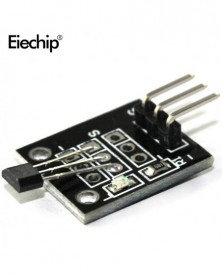
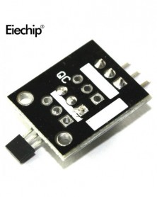
Question: What is the mounting hole diameter and centers dimensions?
Answer: By my measurements, the pcb is 19x15mm and the holes are 10mm apart from centers with 1.5mm diameters
Hall Switch Integrated Circuit Using hall Effect Principle
USES The Semiconductor Integrated Technology Manufacturing Magnetic Susceptibility of the Circuit
Its Input For the Magnetic Induction Intensity, the Output is a Digital Voltage Signa
1. Non-Contact Switch
2. Hall Switch Integrated Circuit Using hall Effect Principle,
3. USES The Semiconductor Integrated Technology Manufacturing Magnetic Susceptibility of the Circuit,
4. It is by the Voltage Regulator, Hall Voltage Generator, Differential Amplifier, Schmidt Triggers, Temperature Compensation and the Open Collector Output Stage Circuit Composed of Magnetic Sensitive Sensor Circuit
5. Its Input For the Magnetic Induction Intensity, the Output is a Digital Voltage Signal
Description :
Working voltage:4.5V-24V
Series 3144, hall switch integrated circuit using hall effect principle, USES the semiconductor integrated technology manufacturing magnetic susceptibility of the circuit, it is by the voltage regulator, hall voltage generator, differential amplifier, schmidt triggers, temperature compensation and the open collector output stage circuit composed of magnetic sensitive sensor circuit, its input for the magnetic induction intensity, the output is a digital voltage signal.
Hall magnetic sensor module and a digital 13 interface with LED build a simple circuit, to produce a magnetic flasher .Use digital 13 interface with the LED, the Hall magnetic sensor connected to the force plate number 3 for ARDUINO interface. When the Hall magnetic sensor to a magnetic field signal , LED lights on, versa lights off.
Reference Program:
int Led=13;// Definition LED Interface
int SENSOR=3;// Define the Hall magnetic sensor interface
int val;// Defines a numeric variable val
void setup()
{
pinMode(Led,OUTPUT);// Definition LED as output interface
pinMode SENSOR,INPUT);// Defined the Hall magnetic sensor as output interface
}
void loop()
{
val=digitalRead(SENSOR);// The digital interface is assigned a value of 3 to read val
if(val==HIGH)// When the shock sensor detects a signal , LED flashes
{
digitalWrite(Led, HIGH);
}
Else
{
digitalWrite(Led, LOW);
}
}
Question: Can it be used directly with Arduino/Raspberry pi?
Answer: Yes
Question: Does it come with LED?
Answer: Yes.
Question: What is the mounting hole diameter and centers dimensions?
Answer: By my measurements, the pcb is 19x15mm and the holes are 10mm apart from centers with 1.5mm diameters

Szállításii feltételek

Biztonsági feltételek

Visszaküldési feltételek