Kereskedelmi, irodai és ipari
-
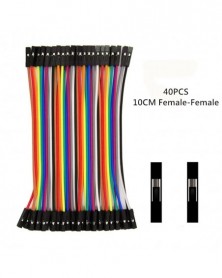
Szín: Nőtől Nőig - Dupont Line 10 cm-es 40 tűs apa-dugó apa-dugasz és anya-nő áthidaló vezeték Dupont kábel az
114 Ft 237 FtDetailed introduction:
40pcs 10cm 2.54mm 1pin Female to Female jumper wire Dupont cable
2.54mm 1pin
Female to Female
Length:10cm
Qty:40pcs(40pcs x 1)
40pcs 10cm 2.54mm 1pin Male to Female jumper wire Dupont cable 2.54mm 1pin Male to Female Length:10cm Qty:40pcs(40pcs x 1)
40pcs 10cm 2.54mm 1pin Male to Male jumper wire Dupont cable
2.54mm 1pin
Male to Male
Length:10cm
Qty:40pcs(40pcs x 1) -
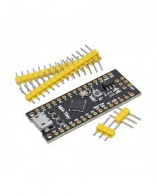
Frissített /NANO V3.0 ATmega328 Extended Kompatibilis az arduino ATTINY88 Micro Development Board 16Mhz-hez /Digispark ATTINY85
201 Ft 419 FtProduct Description
The MH-ET LIVE Tiny88(16.0Mhz) based microcontroller development board similar to the arduino line, only cheaper, smaller, and a bit less powerful. With the ability to use the familiar arduino IDE the MH-ET LIVE Tiny88(16.0Mhz) is a great board to jump into electronics, or perfect for when an other board is too big or too much.The MH-ET LIVE Tiny88(16.0Mhz) is shipped fully assembled except for the headersincluded and easy to solder them by yourself.
Specs:
Support for the arduino IDE 1.0 (OSX/Win/Linux)
1. Power via USB or External Source - 5v or 7-35v (12v or less recommended,
automatic selection)
2. On-board 500ma 5V Regulator
3. Built-in USB
4. 26 I/O Pins (2 are used for USB only if your program actively communicates over USB, otherwise you can use all 6 even if you are programming via USB)
5. 8k Flash Memory (about 6k after bootloader)
6. I2C and SPI
7. 26-PWM (26 pins with Software PWM,only two(D9,D10) with hardware PWM )
8. ADC on 8 pins
9. Power LED and Test/Status LED
10. Size(mm):44.5x18.3x3
PinOut:
Installation Instructions:
First download the appropriate arduino package at the Arduino.cc website: http://www.arduino.cc/en/Main/Software
If using Arduino 1.6.6 or higher and windows - you will need to download and install the drivers manually. Download, unzip and run “Install Drivers” (on 32bit systems) or “DPInst64” (on 64bit systems). The driver files are located here: http://github.com/MHEtLive/MHEtLiveArduino/releases/download/1.0.0/
2.0a4.rar
Install or Unzip the arduino application.
Run the arduino application.
In the arduino application go to the “File” menu and select “Preferences”,In the box labeled “Additional Boards Manager URLs” enter:
http://raw.githubusercontent.com/MHEtLive/arduino-boards-index/master/p
ackage_mhetlive_index.json and click OK;
Go to the "Tools" menu, and then in the "Board" sub-menu-select "Board Manager from the Type drop-down list", and then down select "Submission":
Select the "MH-ET LIVE Boards" package and click the "Install" button.
You will see the download progress on the bottom bar of the "Boards Manager" window, and "Installed" will be displayed next to the item in the list after completion.
WINDOWS users: After the installation is complete, a driver installation wizard window will pop up, please click "Next" in this window to install the MH-ET LIVE driver
Boards (if you have already installed them, this installer will update them and install any missing ones).
After the installation is complete, close the "Boards Manager" window and select MH-ET LIVE Boards "MH-ET LIVE Tiny88(16.0Mhz)" from the Tools→Boards menu.
Choose the example that comes with Arduino IDE: select the development board as MH-ET LIVE Tiny88 in the toolbar, open the program in File>> Example>>Basic>>Blink, and change the port 13 in the program to 0. Follow the above method to transplant, compile and download to MH-ET LIVE Tiny88 (16.0Mhz), you can see the onboard LED light flashes according to the prompt
(Note: When downloading the program, do not connect the module first. After the compilation is completed, wait for the prompt to insert the module, then insert it, and wait for the automatic download to complete). -
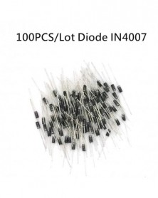
100 db/tétel 1N4007 4007 1A 1000V DO-41 Kiváló minőségű IN4007 1n4007 egyenirányító dióda
108 Ft 224 Ft1N4007
1200V copper feet, overall length>45mm, wire diameter>0.5mm -
KY-008 650 nm lézer érzékelő modul 6mm 5V 5mW Red Laser Dot dióda rézfej
92 Ft 192 FtDescription
Laser sensor Module
Condition: New
Operating voltage 5V
Output wavelength 650 nm
3 pins module
With fixed bolt hole for easy installation
Color: show as pictures
PLS NOTE that due to lighting effects, monitor's brightness / contrast settings etc, there could be some slight differences in the color tone of the pictures and the actual item!
Package Included:
1 x Laser sensor Module -
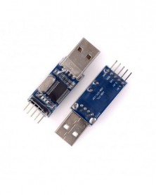
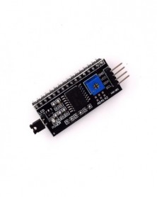
PL2303 USB-RS232 TTL átalakító adapter modul PL2303HX STC mikrokontroller kefe gép kártya
123 Ft 257 FtDescription
Product Name:
USB-TTL level converter board
Application:
1. A variety of satellite STB upgrade
2. routers, hard drives, ADSL, broadband cat or cracked upgrade firmware upgrade
3. Phone, XBOX360, GPS serial communication, vehicle inspection, DVD, etc. Brush
4. STC microcontroller programming, NXP microcontrollers, Renesas microcontrollers, NEC SCM
5. A simple serial communication, HyperTerminal serial debugging tools in common
6. electronics enthusiasts can use the USB signals to TTL signal
Features:
1. Imported new original control chip PL2303HX, high-speed stability Brush
2. Set the two real-time monitoring of data transmission indicator data transfer status
3. reserve 3.3V and 5V pin interface to facilitate the supply of different voltage systems require Brush
4. Interface pin parallel with the board, and the board instead of a vertically mounted, leads DuPont wire brush when convenient
5. The entire circuit board using high-quality transparent coating heat-shrinkable tubing, so that the PCB with the outside world into the insulating state
Thus protecting the metal board is accidentally shorted and burned, due to the use of transparent material, it does not affect the board pick
Watch the opening screen and indicator monitoring results
6. Support WINXP, WIN7 systems (can not support win10)
Now basically a computer with a serial port are rarely, playing board or upgrade some equipment when more trouble, USB-TTL good solution to this problem, the computer did not have to worry about the serial port of the problem, directly into the USB and the other end connected to the development board download port or port to upgrade equipment.
This adapter board USB to TTL chips imported PL2303, which is the most commonly used are the best use of a chip.
To see the board with a very compact and reasonable dual-panel design, using a standard USB connector with the output pin leads, very easy to connect with other board.
Tip: USB-TTL small board with a microcontroller or other products is the connection method:
USB-TTL Microcontroller
TXD <----> RXD
RXD <----> TXD
GND <----> GND -
Szín: 5mm 100db - Fénykibocsátó diódák 5 színű elektronikai alkatrészek 3 mm / 5 mm válogatott színű barkács LED
157 Ft 328 Ft200PCS
40 X 3mm red LED diode
40 X 3mm white LED diode
40 X 3mm green LED diode
40 X 3mm blue LED diode
40 X 3mm yellow LED diode
20 X 5mm red LED diode
20 X 5mm white LED diode
20 X 5mm green LED diode
20 X 5mm blue LED diode
20 X 5mm yellow LED diode
100PCS
20 X 5mm red LED diode
20 X 5mm white LED diode
20 X 5mm green LED diode
20 X 5mm blue LED diode
20 X 5mm yellow LED diode -
Szín: 3mm 200db - Fénykibocsátó diódák 5 színű elektronikai alkatrészek 3 mm / 5 mm válogatott színű barkács LED
174 Ft 363 Ft200PCS
40 X 3mm red LED diode
40 X 3mm white LED diode
40 X 3mm green LED diode
40 X 3mm blue LED diode
40 X 3mm yellow LED diode
20 X 5mm red LED diode
20 X 5mm white LED diode
20 X 5mm green LED diode
20 X 5mm blue LED diode
20 X 5mm yellow LED diode
100PCS
20 X 5mm red LED diode
20 X 5mm white LED diode
20 X 5mm green LED diode
20 X 5mm blue LED diode
20 X 5mm yellow LED diode -
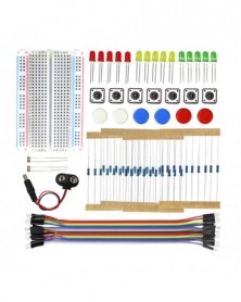
Starter Kit Mini Breadboard LED Jumper Wire gomb Arduino DIY Kit School Education Labhoz
204 Ft 425 FtPackage include
1 ×400 holes Breadboard
5 ×3 colors of LED lights(random)
10×Resistor 220ohm
10×Resistor 1K
10×Resistor 10K
10×Resistor 100K
2 ×Photoresistor 5516
6 ×Button(with the mixed color caps)
1 ×9V Batteryt Connector
20 ×male to male dupont cable -
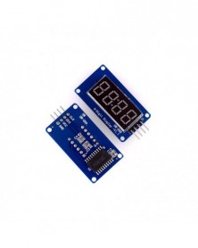
TM1637 LED kijelző modul 7 szegmens, 4 bit, 0,36 hüvelykes óra, VÖRÖS anód digitális cső, négy soros meghajtó
120 Ft 249 FtDescription
Module features are as follows:
1. Display common anode for the four red LED
2. Digital tube 8 gray adjustable
3. Level control interface for 5V or 3.3V
4. Size:42X24X12mm -
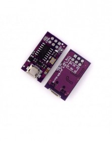
Micro USB Tiny AVR ISP ATtiny44 USBTinyISP programozó modul IDE rendszerbetöltő ISP mikrokontroller 5V F03-07
208 Ft 434 FtDescribe:
USBtinyISP is specially designed for AVR, ISP download based on USB connector.
Officially supported by AR IDE and compatible usbtinyisp, we can burn the AR bootloader onto the chip and actually program any Atmel AVR microcontroller through the powerful AVR ISP programmer.
The micro ISP programmer can provide 5V power supply voltage for the board being programmed. If you want to supply power to the circuit board through ISP, you must close the SJVCC jumper on the circuit board.
Using this programmer, you can upload sketches and burn Bootloader on any AVR-based circuit board, including AR. By using an external programmer to upload the sketch, you can delete the bootloader and use extra space for the sketch. For AR ISP can also be used to burn AR bootloader, so if the bootloader is accidentally damaged, you can restore the chip. When you use the new ATmega microcontroller in AR, you also need to burn the bootloader, and you want to use the bootloader to upload the sketch via a USB serial connection. Support ATTiny45 and ATTiny85 chips for AR programming, etc.
specification:
Power supply voltage: 5 V
Microcontroller: ATtiny44 (data sheet)
Connect with computer: micro USB
Connection with target board: ICSP
Board size: 23x14mm (approximately)
how to use:
Connect the AR ISP to the ICSP header of the AR board. Make sure to match the orientation of the plug by looking at the white dots on the corners of the connector
Open the AR IDE, select the hardware name downloaded in the "board", select "USBtinyISP" under the "Burn Bootloader" menu, and then bootlaoder starts downloading and completes in 10 seconds (atmega328) -
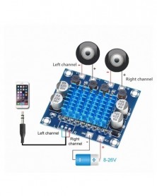
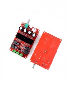
TPA3110 XH-A232 30W 30W 2.0 csatornás digitális sztereó audio teljesítményerősítő kártya DC 8-26V 3A C6-001
190 Ft 396 FtProduct description:
Parameter:
Chip: TPA3110
Condition:XH-A232
Application:Computer
Supply Voltage:DC8V-26V
Dissipation Power:30W 30W
Size:53*45*14mm
Channels:2 (2.0)
Output impedance:4-8ohm
Current: more than 3A
Signal to noise ratio: 100db
Package ncluded:
1PC TPA3110 Digital Power Audio Amplifier Board -
Szín: 1602 fehér - LCD1602 1602 modul kék/zöld képernyő IIC/I2C 16x2 karakteres LCD kijelző modul.1602 5V zöld
230 Ft 480 FtProduct Description
1602 LCD:
LCD display module with blue/Green/White blacklight.
Wide viewing angle and high contrast.
Built-in industry standard HD44780 equivalent LCD controller.
Commonly used in: copiers, fax machines, laser printers, industrial test equipment, networking equipment such as routers and
storage devices.
LCM type: Character
Can display 2-lines X 16-characters.
Voltage: 5V DC.
Module dimension: 80mm x 35mm x 11mm.
Viewing area size: 64.5mm x 16mm
IIC
1602 I2C interface 4-wire 1602 screen
IO port of Arduino control board is only 20,so IO ports is not enough for many sensor, SD card, relay modules.
The original 1602 screen need 7 IO ports to drive up, and this module can save 5 IO ports -
Szín: 1602 kék - LCD1602 1602 modul kék/zöld képernyő IIC/I2C 16x2 karakteres LCD kijelző modul.1602 5V zöld képernyő
214 Ft 445 FtProduct Description
1602 LCD:
LCD display module with blue/Green/White blacklight.
Wide viewing angle and high contrast.
Built-in industry standard HD44780 equivalent LCD controller.
Commonly used in: copiers, fax machines, laser printers, industrial test equipment, networking equipment such as routers and
storage devices.
LCM type: Character
Can display 2-lines X 16-characters.
Voltage: 5V DC.
Module dimension: 80mm x 35mm x 11mm.
Viewing area size: 64.5mm x 16mm
IIC
1602 I2C interface 4-wire 1602 screen
IO port of Arduino control board is only 20,so IO ports is not enough for many sensor, SD card, relay modules.
The original 1602 screen need 7 IO ports to drive up, and this module can save 5 IO ports -
Szín: 1602 zöld - LCD1602 1602 modul kék/zöld képernyő IIC/I2C 16x2 karakteres LCD kijelző modul.1602 5V zöld képernyő
214 Ft 445 FtProduct Description
1602 LCD:
LCD display module with blue/Green/White blacklight.
Wide viewing angle and high contrast.
Built-in industry standard HD44780 equivalent LCD controller.
Commonly used in: copiers, fax machines, laser printers, industrial test equipment, networking equipment such as routers and
storage devices.
LCM type: Character
Can display 2-lines X 16-characters.
Voltage: 5V DC.
Module dimension: 80mm x 35mm x 11mm.
Viewing area size: 64.5mm x 16mm
IIC
1602 I2C interface 4-wire 1602 screen
IO port of Arduino control board is only 20,so IO ports is not enough for many sensor, SD card, relay modules.
The original 1602 screen need 7 IO ports to drive up, and this module can save 5 IO ports -
Szín: IIC - LCD1602 1602 modul kék/zöld képernyő IIC/I2C 16x2 karakteres LCD kijelző modul.1602 5V zöld képernyő és
167 Ft 347 FtProduct Description
1602 LCD:
LCD display module with blue/Green/White blacklight.
Wide viewing angle and high contrast.
Built-in industry standard HD44780 equivalent LCD controller.
Commonly used in: copiers, fax machines, laser printers, industrial test equipment, networking equipment such as routers and
storage devices.
LCM type: Character
Can display 2-lines X 16-characters.
Voltage: 5V DC.
Module dimension: 80mm x 35mm x 11mm.
Viewing area size: 64.5mm x 16mm
IIC
1602 I2C interface 4-wire 1602 screen
IO port of Arduino control board is only 20,so IO ports is not enough for many sensor, SD card, relay modules.
The original 1602 screen need 7 IO ports to drive up, and this module can save 5 IO ports -
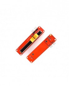
Csúsztatható potenciométer 10K Ohm lineáris modul analóg érzékelő, kettős kimenet az arduino AVR elektronikus blokk
160 Ft 334 FtFeature:
USES the high quality slide appliances, stable and reliable performance
Dual analog output, 0 - VCC analog voltage signal
Specification:
Size: 90 * 20 mm
Color: Red
Voltage: 3.3 V, 5 V
Port: analog
Resistance: 10 K
Platform: For Arduino MCU ARM and other single chip -
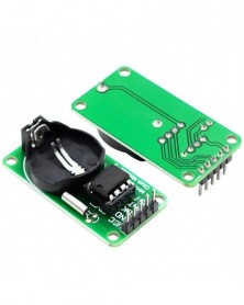
RTC DS1302 valós idejű óramodul AVR ARM PIC SMD-hez arduino-hoz
103 Ft 214 FtDS1302 real-time clock module
DS1302 is a trickle charge clock chip introduced by DALLAS, which contains a real-time clock/calendar and 31 bytes of static RAM, and communicates with the microcontroller through a simple serial interface. The real-time clock/calendar circuit provides information of seconds, minutes, hours, days, weeks, months, and years. The number of days in a month and the number of days in a leap year can be adjusted automatically. Clock operation can be determined by AM/PM indication to adopt 24 or 12 hour format. The DS1302 and the single-chip microcomputer can simply use the synchronous serial way to communicate, only three ports are needed: (1) RST reset (2) I/O data line (3) SCLK serial clock. The read/write data of the clock/RAM is communicated in a byte or burst of up to 31 bytes. The DS1302 has very low power consumption when working, and the power is less than 1mW while maintaining data and clock information
Main performance indicators of DS1302:
★ The real-time clock has the ability to calculate seconds, minutes, hours, days, weeks, months, and years before 2100, as well as the ability to adjust leap years
★ 31 8-bit temporary data storage RAM
★ Serial I/O port mode makes the number of pins less
★ Wide range of working voltage 2.0 5.5V
★ When the working current is 2.0V, less than 300nA
★ There are two transmission methods when reading/writing clock or RAM data: single-byte transmission and multi-byte transmission character group method
★ 8-pin DIP package or optional 8-pin SOIC package according to surface assembly
★ Simple 3-wire interface
★ Compatible with TTL Vcc=5V
★ Optional industrial temperature range -40 85
★ Dual power supply tubes are used for main power supply and backup power supply
The parameters of the DS1302 real-time clock module are as follows:
1. The PCB is a single panel, size: 44mm*23mm*1.6mm
2. With 4 positioning holes, diameter 3.1mm
3. The backup battery is Celestial CR2032, voltage 3V, current 260mAh, non-rechargeable battery. The theoretical data retention time is more than 10 years!
4. The crystal oscillator is 32.768KHz, imported from Japan, the matching capacitance is 6pF, and the size is 2*6mm
5. DS1302 is a large 8-pin direct-insertion chip made in China. There is an IC socket under the chip, which is convenient to replace and plug the chip.
6. The working voltage of the module is compatible with 3.3V/5V and can be connected with 5V and 3.3V microcontrollers
7. Working temperature: 0°---70°
Wiring method (take the provided program as an example, you can connect to any IO port, just modify the port definition in the program):
VCC→ 5V/3.3V
GND→GND
CLK→P02
DAT→P01
RST→P00
Precautions:
1. Don't connect VCC and GND reversely, so as not to burn out the chip
2.51 The P0 port of the single-chip microcomputer needs to be connected with a pull-up resistor. If your single-chip microcomputer is not connected with a pull-up resistor, you can connect the data line to other ports -
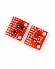
Szín: BMA220 - BMA220 BMA250E BMA280 háromtengelyes gravitációs érzékelő BMA222 kicsi, három tengelyes alacsony G
208 Ft 434 FtFeature:
1.100% brand new and high quality!
2.Small volume,a new generation of sensor circuit board area reduced by 79% .but the reduction of product size does not imply a loss of function or quality.
3.Can greatly reduce the energy consumption of mobile devices and significantly extend battery life
4.Analytical electronics integrated into the sensor, replacing the dense signal analysis performed by the microcontroller of the host application system
5.Programmable measurement range with electronic data output, four-section ±2g to ±16g, and integrated analyzer for recognizing specific mobile patterns
Specification:
Main color:red
Weight:2g
Main unit size:21*18*1mm
Note:
Please allow 1-3mm error due to manual measurement. pls make sure you do not mind before you bid
Due to the difference between different monitors, the picture may not reflect the actual color of the item. Thank you!
Package included:
1 x BMA220/BMA250E/BMA280/BMA222 Shaft Gravity Sensor -
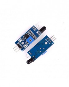
Intelligens elektronikai fényvisszaverő fotoelektromos 3 tűs IR infravörös akadályelkerülő érzékelő modul barkácsolt
88 Ft 183 FtDescription
The sensor module has strong adaptability to ambient light. It has a pair of infrared emitting and receiving tubes. The emitting tube emits a certain frequency of infrared rays. When the detection direction encounters an obstacle (reflecting surface), the infrared rays are reflected back and received by the receiving tube. After being processed by the comparator circuit, the green indicator light will light up, and the signal output interface will output a digital signal (a low-level signal). The detection distance can be adjusted by the potentiometer knob. The effective distance range is 2-30cm, and the working voltage is 3.3V- 5V. The detection distance of the sensor can be adjusted by a potentiometer, has the characteristics of low interference, easy assembly, and convenient use. It can be widely used in many occasions such as robot obstacle avoidance, obstacle avoidance trolley, assembly line counting and black and white line tracking. Module parameter description 1 When the module detects the front obstacle signal, the green indicator light on the circuit board lights up, and the OUT port continues to output low-level signals. The module has a detection distance of 2~30cm, a detection angle of 35°, and the detection distance can pass the potential Adjust the potentiometer clockwise to increase the detection distance; adjust the potentiometer counterclockwise to decrease the detection distance. 2. The sensor takes active infrared reflection detection, so the reflectivity and shape of the target are the key to the detection distance. Among them, the black detection distance is the smallest, and the white is the largest; the distance of a small area is small, and the distance of a large area is large. 3. The output port OUT of the sensor module can be directly connected to the IO port of the single-chip microcomputer, or can directly drive a 5V relay; connection mode: VCC-VCC; GND-GND; OUT-IO 4. The comparator adopts LM393, which works stably; 5. 3-5V DC power supply can be used to power the module. When the power is turned on, the red power indicator lights up; 6. With 3mm screw holes, easy to fix and install; 7. Circuit board size: 3.2CM*1.4CM 8. The threshold comparison voltage of each module has been adjusted through the potentiometer before delivery. Please do not adjust the potentiometer at will if it is not a special case. Module interface description 1 VCC external 3.3V-5V voltage (can be directly connected with 5v microcontroller and 3.3v microcontroller) 2 GND External GND 3 OUT Small board digital output interface (0 and 1) -
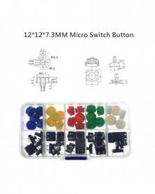
25 DB tapintható nyomógombos pillanatnyi kapcsolókészlet
174 Ft 363 FtNote: The button hat color is sent randomly
1. The rated range: 50 ma 12 VDC
2. Contact resistance: 50 m Ω Max (initial)
3. The insulation resistance: 100 m Ω minDC (250 v)
4. The compressive strength: AC250V (50/60 hz for 1 minute)
5. Mechanical life: 100000 cycles
6. The environment temperature: 25 ° ~ 105 °
7. The operating strength: 180/250 (plus or minus 30 gf)
12 * 12 * 7.3 round convex type -
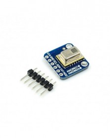
AMG8833 IR 8x8 hőkamera tömb hőmérséklet-érzékelő modul a Raspberry Pi GY-AMG8833-hoz
2 543 Ft 5 297 FtProduct Parameters
1. Accuracy: - 2.5°C (4.5°F).
2. Maximum frame rate: 10Hz,
3. Power supply: 3~5V
4. Temperature Measurement Range: 0°C to 80°C (32°F to 176°F)
Product Description
1. The AMG8833 infrared camera sensor is an 8x8 infrared thermal sensor array. When connected to your microcontroller (or Raspberry Pi), it will return a set of 64 individual infrared temperature readings via I2C. It's like those fancy thermal cameras, but it's compact and simple and easy to integrate. The AMG8833 offers higher performance than the previous AMG8831. The sensor only supports I2C and has a configurable interrupt pin that can be triggered when any single pixel is above or below your set threshold.
2. It can detect humans from a distance of up to 7 meters (23) feet. It is a perfect fit for creating your own human detector or mini camera. We use this breakthrough code on or compatible (sensor communicates via I2C) or on Python's Raspberry Pi. On the Pi, thanks to the image processing help of the SciPy python library, we can insert an 8x8 grid and get some very good results! -
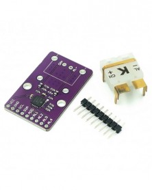
CJMCU-96 MCP9600 típusú K/J/T/N/S/E/B/ R hőelem átalakító modul támogatja az I2C IIC interfész hőmérséklet
3 111 Ft 6 482 FtProduct Description
CJMCU-96 MCP9600 Type K/T/J Thermocouple Converter Module Supports I2C IIC Interface EMF Temperature Conversion
Features:
1. Scope of application: This product can correct the thermocouple nonlinear error characteristics of 8 thermocouple types, including K, J, T, N, S, E, B and R, which are very practical.
2. High accuracy: The calibration factor of this product comes from the National Institute of Standards and Technology (NIST) ITS-90 thermocouple database. The measurement accuracy is ±1.5 °C, so the accurate temperature data of the selected thermocouple can be output.
3. With User-Programmable Registers: This product features user-programmable registers that provide design flexibility for a variety of temperature sensing applications.
4. Four programmable temperature alarm outputs and digital filters: This product features an adjustable digital filter with fast transient temperature and four individually programmable temperature alarm outputs for detecting multiple temperature zones.
5. Low power consumption: This product uses low power consumption, has shutdown mode and burst mode, can save power and is very environmentally friendly.
Descriptions:
1. CJMCU-96 is a fully integrated thermocouple electromotive force (EMF) Celsius converter module with cold junction compensation.
2. CJMCU-96 supports eight types of thermocouples (K, J, T, N, S, E, B and R) and provides user-programmable registers to enhance design flexibility for a variety of temperature sensing applications .
Specifications:
Color: Purple
Supported types (specified by NIST ITS-90): K, J, T, N, S, E, B, and R
Measurement accuracy: ±1.5 ° C (maximum)
Cold end: 0°C to 85°C, ±1°C (maximum)
Temperature measurement resolution: hot and cold junction = 0.0625°C (typ.)
Low power consumption: shutdown mode, burst mode, 1 to 128 temperature samples
Two-wire interface: I2C compatible, 100 kHz - 8 devices per I2C bus
Operating voltage range: 2.7 V to 5.5 V.
Working current: 500μA (typical)
Shutdown current: 2μA (typical)
Package Included:
1 x CJMCU-96 MCP9600 Type K/T/J Thermocouple Converter -
1 db 16 bites ADC 8 csatornás szinkronizációs AD7606 adatgyűjtő modul 200 Ksps
1 914 Ft 3 988 FtProdect description:
Tip : To facilitate your choice , PCB board analog input front -row pin (2x8/2.54mm pitch ) default not weld .
We will be giving away 2x8 's double needle and eight jumpers from the customer's own choice is up welding,
soldering or down .
1, using high-precision 16-bit ADC chip AD7606
2,8 analog inputs. 1M ohm impedance.[No negative supply, there is no front-end analog amplifier can be
connected directly to the sensor output]
3, the input range of plus or minus 5V, plus or minus 10V. By IO control.
4, Resolution 16.
5, the maximum sampling frequency sampling rate of 200ksps.
Supports eight sampling settings file (which can effectively reduce the jitter)
6, built-in benchmark
7, a single 5V power supply
8, SPI Interface, or 16-bit bus interface. Interface IO level can be 5V or 3.3V.
We AD7606 module factory default is 8080 parallel interface.
If SPI interface mode, you need to modify R1 R2 resistor configuration.
Parallel Mode Jumper: R1 floating (not stickers), R2 10K resistor paste
SPI interface mode jumper: R1 stickers 10K resistor, R2 floating (not stickers)
AD7606 configuration is very simple, it has no internal registers.
Range and over-sampling parameters are controlled via an external IO.
Pulse frequency sampling rate provided by the microcontroller or DSP control.
AD7606 must use a single 5V supply.
Level communication interface between the AD7606 and SCM controlled by VIO pin.
That VIO power supply must be connected to the microcontroller can be 3.3V can also be 5V.
[Module Pin Description]
OS2 OS1 OS2: a combination of state selection oversampling mode.
000 means no oversampling, the maximum sampling rate of 200ksps.
001 represents two times oversampling, which is the hardware inside collected two samples averaging
010 represents four times oversampling, which is the hardware inside collect four samples averaged
011 represents eight times oversampling, which is the hardware inside collected eight samples averaged
100 represents 16 times oversampling, which is the hardware inside collected 16 samples averaged
101 represents 32 times oversampling, which is an internal hardware averaging collected 32 samples
110 represents 64 times oversampling, which is the hardware inside collected 64 samples averaged
Oversampling ratio is higher, the longer the ADC conversion time, the lower the maximum sampling
frequency can be obtained.
CVA, CVB: AD conversion start control signal channel 1-4 decision CVA, CVB decided 5-8 channels.
Two signals can stagger a short time, in general, can be CVA, CVB parallel together.
RAGE: Select the range of 0 means plus or minus 5V, 1 indicates negative 10V.
RD: Read signal
RST: Reset signal
Busy: Busy Signal
CS: chip-select signal
FRST: first a channel samples indicating signal
VIO: communication interface level
DB0 - DB15: Data Bus
[16 parallel mode wiring diagram --- AD7606 also supports 8-bit bus mode, see the AD7606 data sheet
MCU side AD7606 module
GND <----- ground
5 V <----- 5V power supply
RAGE <----- can also be connected to the GPIO connected fixed level
OS2 <----- can also be connected to the GPIO connected fixed level
OS1 <----- can also be connected to the GPIO connected fixed level
OS0 <----- can also be connected to the GPIO connected fixed level
CVA <----- access the GPIO (output) is used to start AD conversion [Recommended pick pin with PWM output
capability]
CVB <--- |
RD <----- 8080 bus read signal NOE
RST <----- GPIO output hardware reset AD606
Busy -----> GPIO input AD606 being converted instructions. [Recommended connection with external
pin interrupt capability]
CS <----- 8080 bus chip select NCS
VIO <----- microcontroller power supply
DB0-DB15 -----> 8080 data bus (16)
FRST may take
[SPI interface mode wiring diagram
MCU side AD7606 module
GND <----- ground
5 V <----- 5V power supply
RAGE <----- any output GPIO, can be accessed by a fixed level
OS2 <----- any output GPIO, can be accessed by a fixed level
OS1 <----- any output GPIO, can be accessed by a fixed level
OS0 <----- any output GPIO, can be accessed by a fixed level
CVA <----- access the GPIO (output) is used to start AD conversion [Recommended pick pin with PWM
output capability]
CVB <--- |
RD / SCLK <----- SPI bus clock SCK
RST <----- any output GPIO, for hardware reset AD606
Busy -----> GPIO input, AD606 being converted instructions. [Recommended connection with external
pin interrupt capability]
CS <----- SPI bus chip select SCS
VIO <----- microcontroller power supply
DB7 (DOUTA) -----> SPI bus data lines MISO
DB14 - DB15 may pick
FRST may take
Software implementations [1] --- timing acquisition of SPI example we offer document using this program,
see bsp_spi_ad7606.c
In the timer interrupt service routine implementation:
Timer interrupt ISR:
{
Interrupt entry;
8 reads the sampling results are stored in the RAM channel; ----> read is the last record collection for continuous
acquisition, it is not related to the
Start next ADC acquisition; (flip CVA and CVB)
Interrupt return;
}
Timer frequency is the ADC sampling frequency. This mode can not connect busy port cable.
Software implementations [2] --- timed 8080 acquisition of the interface we provide an example of using
this program, see bsp_ad7606.c file
Configure CVA CVB pin PWM output mode, the sampling period is set to the desired frequency; ---> After
the MCU will produce a very stable AD conversion cycle signal
The busy port line is set to interrupt falling edge trigger mode;
External interrupt ISR
{
Interrupt entry;
8 reads the sampling results of the channel stored in the RAM;
Interrupt return;
}
[1 and 2, the differences in implementations of software-timed acquisition]
(1) Option 1 may be less busy lines, but the other main interrupt service routine or temporary closure of
the global interrupt when ADC conversion cycle may cause a slight jitter.
(2) Option 2 can ensure the stability of the acquisition of the clock, because it is generated by the MCU
hardware, but need more then a BUSY mouth lines. -
Mega 2560 PRO MINI 5V (beágyazott) CH340G ATmega2560-16AU dugós tűfejekkel
1 695 Ft 3 532 FtProduct Description
Embed version of Mega 2560 CH340G/ATmega2560 - compatible with arduino Mega 2560 board. Built on the Atmel ATmega2560 microcontroller and USB-UART interface chip CH340G.
Board have compact size 38x55mm. It is good solution, to make your final project on solder proto-board.
Board for functionality similar to the arduino Mega 2560. It is embed board, but the same stable, and uses the original chips ATmega2560 (16 MHz).
The board used the chip CH340G as converter UART-USB. When you work in the frequency 12Mhz, giving a stable result of data exchange (need install drivers to computer).
Mega PRO (Embed) 2560 CH340G / ATmega2560 - connects to the computer via microUSB cable (used for almost all Android smartphones).
You can supply power to board through the MicroUSB connector or to power pinheaders. The voltage regulator (LDO) can deal with incoming voltage from 6V to 9V (peack 18V) DC. Output current for 5V - about 800mA, for 3.3V - about 800mA (Please note that the higher the input voltage the lower the outgoing current). That will provide a reliable power most of your initial projects. -
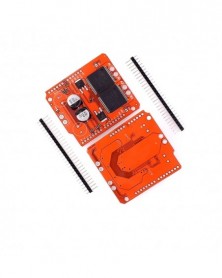
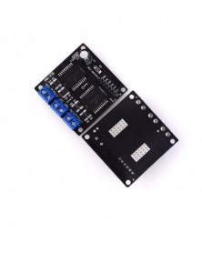
Monster Moto Shield VNH2SP30 léptetőmotor meghajtó modul nagyáramú 30A
1 723 Ft 3 589 FtDescription
For this monster shield we\'ve replaced the L298 H-bridge with a pair of VNH2SP30 full-bridge motor drivers. We\'ve also beefed up the support circuitry so this board is capable of driving a pair of high-current motors! The VIN and motor out are pitched for our 5mm screw terminals (not included), making it easy to connect larger gauge wires.
Note: When using this board in extreme high-demand applications it may be necessary to improve thermal performance with a heat-sink or fan and to solder the wires directly to the board instead of using a screw terminal (in addition to the myriad other complications present in a high-current system) However, when using the board at currents up to 6A the chips will barely become noticeably warm.cjmcu
Features:
Voltage max: 16V
Maximum current rating: 30 A
Practical Continuous Current: 14 A
Current sensing available analog pin
MOSFET on-resistance: 19 mΩ (per leg)
Maximum PWM frequency: 20 kHz
Thermal Shutdown
Undervoltage and Overvoltage shutdown -
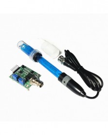
Szín: PH modul - Folyékony PH érték észlelése Érzékelő érzékelő modul felügyelő vezérlőkártya BNC elektród
1 071 Ft 2 232 FtProduct Description
Heating voltage: 5±0.2V (AC -• DC)
Working current: 5-10mA
The detection concentration range: PH0-14
The detection range of temperature: 0-80 centigrade
The response time: ≤ 5S
Stability time: ≤ 60S
Power consumption: ≤ 0.5W
The working temperature: -10~50 centigrade (the nominal temperature 20 centigrade)
Working humidity: 95% RH (nominal humidity 65% RH)
Service life: 3 years
Size: 42mm x 32mm x 20mm
The output: analog voltage signal output
BNC PH Electrode Probe
The PH electrode has a single cylinder that allows direct connection to the input terminal
of a PH meter, controller, or any PH device which has a BNC input terminal.
The PH electrode probe is accurate and reliable that can gives almost instantaneous readings.
PH range: 0-14 PH
Temperature range: 0-60℃
Zero-point: 7 ± 0.5PH
Alkali Error: 0.2PH
Theoretical Percentage Slope: ≧98.5%
Internal Resistance: ≦250MΩ
Response Time: ≦1min
Operating Temperature: 0-60℃
Terminal Blocks: BNC plug
BNC Connector suitable for most PH meter and controller.
Suitable for wide range of application: Aquariums, Hydroponics, Laboratory etc.
Note:
1.Do not include the box.
2.Refillable PH probe (blue)
3.Non-fillable PH probe (black)
Package included(You can choose it):
1 x PH Module and PH Probe -
Szín: PH szonda - Folyékony PH érték észlelése Érzékelő érzékelő modul felügyelő vezérlőkártya BNC elektród
1 123 Ft 2 339 FtProduct Description
Heating voltage: 5±0.2V (AC -• DC)
Working current: 5-10mA
The detection concentration range: PH0-14
The detection range of temperature: 0-80 centigrade
The response time: ≤ 5S
Stability time: ≤ 60S
Power consumption: ≤ 0.5W
The working temperature: -10~50 centigrade (the nominal temperature 20 centigrade)
Working humidity: 95% RH (nominal humidity 65% RH)
Service life: 3 years
Size: 42mm x 32mm x 20mm
The output: analog voltage signal output
BNC PH Electrode Probe
The PH electrode has a single cylinder that allows direct connection to the input terminal
of a PH meter, controller, or any PH device which has a BNC input terminal.
The PH electrode probe is accurate and reliable that can gives almost instantaneous readings.
PH range: 0-14 PH
Temperature range: 0-60℃
Zero-point: 7 ± 0.5PH
Alkali Error: 0.2PH
Theoretical Percentage Slope: ≧98.5%
Internal Resistance: ≦250MΩ
Response Time: ≦1min
Operating Temperature: 0-60℃
Terminal Blocks: BNC plug
BNC Connector suitable for most PH meter and controller.
Suitable for wide range of application: Aquariums, Hydroponics, Laboratory etc.
Note:
1.Do not include the box.
2.Refillable PH probe (blue)
3.Non-fillable PH probe (black)
Package included(You can choose it):
1 x PH Module and PH Probe -
Szín: modul és szonda - Folyékony PH érték észlelése Érzékelő érzékelő modul felügyelő vezérlőkártya BNC
1 765 Ft 3 677 FtProduct Description
Heating voltage: 5±0.2V (AC -• DC)
Working current: 5-10mA
The detection concentration range: PH0-14
The detection range of temperature: 0-80 centigrade
The response time: ≤ 5S
Stability time: ≤ 60S
Power consumption: ≤ 0.5W
The working temperature: -10~50 centigrade (the nominal temperature 20 centigrade)
Working humidity: 95% RH (nominal humidity 65% RH)
Service life: 3 years
Size: 42mm x 32mm x 20mm
The output: analog voltage signal output
BNC PH Electrode Probe
The PH electrode has a single cylinder that allows direct connection to the input terminal
of a PH meter, controller, or any PH device which has a BNC input terminal.
The PH electrode probe is accurate and reliable that can gives almost instantaneous readings.
PH range: 0-14 PH
Temperature range: 0-60℃
Zero-point: 7 ± 0.5PH
Alkali Error: 0.2PH
Theoretical Percentage Slope: ≧98.5%
Internal Resistance: ≦250MΩ
Response Time: ≦1min
Operating Temperature: 0-60℃
Terminal Blocks: BNC plug
BNC Connector suitable for most PH meter and controller.
Suitable for wide range of application: Aquariums, Hydroponics, Laboratory etc.
Note:
1.Do not include the box.
2.Refillable PH probe (blue)
3.Non-fillable PH probe (black)
Package included(You can choose it):
1 x PH Module and PH Probe -
CJMCU-SHT10 SHT11 hőmérséklet- és páratartalom-érzékelő fejlesztőkártya modul
1 274 Ft 2 654 FtModel:CJMCU-SHT10 CJMCU-SHT10 The temperature and humidity sensor The development module
SHTxx Series single chip sensor is a type containing calibrated number
Temperature and humidity composite sensor with word signal output.It applies patented industry
COMS The process of micro processing technology(CMOSens®),To ensure that the product
It has extremely high reliability and long-term stability.The sensor includes a
A capacitive aggregation body measurement wet element and an energy gap thermometric element,
And with a14 Bits ofA/D Converter and serial interface circuit are the same
Seamless connection on one chip.So,The product has quality
Ultra-fast response,Strong anti-interference ability,High cost performance advantages.
Each SHTxx The sensors are all in the precise humidity calibration room
Line calibration.Calibration coefficient is stored in the form of programOTP Memory
In,These should be called in the processing process of detection signal inside the sensor
The calibration coefficient.
Two-wire serial interface and internal reference voltage,The system integrated variable
Have simple and rapid.Small Volume,Low power consumption,To make them become
The selection of similar applications or even harsh applications.
Application areas
_ Ventilation and air conditioning (HVAC) HVAC
_ Car
_ Consumer goods
_ The weather station
_ Humidity regulator
_ The dehumidifier
_ Test and testing equipment
_ Data logger
_ Automatic control
_ Household appliances
_ Medical -
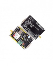
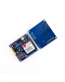
SIM808 SIM908 modul helyett GSM GPRS GPS fejlesztőtábla IPX SMA GPS antennával Raspberry Pi-hez
1 643 Ft 3 423 FtDescription:
1.Three power input interface: DC044 interface and V_IN and a lithium battery interface.
Note that: The range of DC044 and the V_IN pin voltage input is 5 - 26V, when use the 5V as the power, be sure that the power supply can provide 2A current. The range of voltage of Lithium battery input power is 3.5 - 4.2V.
2. Switch: It is used to open / close the input power supply for the module. When in use, please confirm the toggle switched to the OPEN state (near the board inside).
3. SMA antenna interface: there is a GSM antenna interface, a GPS antenna interface onboard and a BT antenna interface.
4. Start button: When the board is power on, the LED (PWR) will light up. After a long press (about 2 second) on this button, the other three LEDs will be light. And one of them starts to flash; this suggests that SIM808 is beginning to work now. When the power supply, GSM and GPS antenna and SIM card are connected to the module correctly, the LED will be flash slowly (3Second de 1second light), that indicates that the module is registered to the network, and you can make a call or do something else.
5. TTL serial interface: a TTL level interface. Notice that: The pin of VMCU is used to control the high level of TTL UART, so as to realize to match between 1.25V/3.3V /5V systems. For example, if you want to use the 51 MCU to control this board, the pin of VMCU should be connected the DC5V. And if use the STM32 MCU, the pin of VMCU should be connected the DC3.3V. The pins of RXD is the RXD of SIM808 and the pins of TXD is the TXD of SIM808. The pin of V_IN can connect the Power, the function of this pin has the same function of DC044.
6. USB interface: This interface is just use to update the firmware of SIM808 module.
Operation Description:
1. Preparation:
SIM808 SHIELD
DC9V adapter
USB-TTL module or other tools.
PC software
2. Hardware configurations
2.1 Connect the USB-TTL to the UART interface
USB-TTL SIM808
TXD RXD
RXD TXD
GND GND
2.2 Insert the valid SIM card to the SIMCARD holder.
2.3 Connect the GPS antenna and GSM antenna to the board
Connect the power adapter to the DC044 Interface
2.4 Change the switch
2.6 Press the POWKEY button for 2 second, the SIM808 module will work and the other 3 LEDs will light.
Document Link:https://www.adrive.com/public/P7QRkq/FZ1735-SIM808% 20% E5% A4% A7V3.1.rar
Package Included:
1 X SIM808 Moudle
1 X GSM Antenna
1 X GPS Antenna -
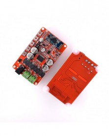
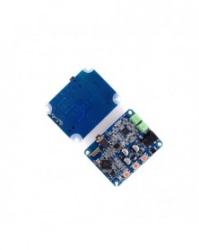
TDA7492 vezeték nélküli Bluetooth 4.0 2 x 50 W 2 csatornás audio vevő sztereó digitális végerősítő kártya modul 10 V
1 422 Ft 2 962 FtDescribe
Sound quality is very good by using this module.
Using CSR8635 Bluetooth chip, Bluetooth V4.0, high software compatibility.
Power amplifier chip: TDA7492 double channels sufficient power 50W, better than TDA7492P.
With microphone (can call with Bluetooth), AUX interface(wired mode audio input).
With 5 buttons for adjustment, convenient and easy operation.
Specifications:
Supply Voltage: DC 10-25V
Power Interface: 2.1 DC Socket
Audio Input: Bluetooth Receiver V4.0
Amplifier Chip: TDA7492
Output Power: 2*50W
Applicable Speaker Impedance: 4/6/8/16 ohm
Number of Channels: Two-channel Stereo
PCB Board Size: 81 * 58mm / 3.2 * 2.3in
Weight: 47g
Package List:
1 * Bluetooth 4.0 Audio Receiver Power Amplifier Board -
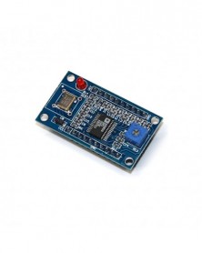
AD9850 DDS jelgenerátor modul, 0-40 MHz, 2 szinuszos és 2 négyzetes aluláteresztő szűrő, kristályoszcillátor
1 386 Ft 2 887 FtFeatures:
1. AD9850: 0-40MHz.
2. 2 sine wave and 2 square wave output.
3. After the 20-30MHz frequency harmonics increases, the waveform will be less and less clean.
4. Square Wave: 0-1MHz.
5. Low-pass filter with 70MHz, so the waveform better than SN.
6. Parallel and serial data input can be selected via a jumper.
7. DA produced the benchmark pin (PIN12) leads for easy adjustment to do the magnitude of the output waveform Application.
8. Comparator reference input voltage generated by the variable resistor, the resistor can be adjusted duty cycle square wave of different.
9. Active AD9850 125MHz crystal oscillator modules.
10. Dimension:4.5cm x 2.6cm
Package Included:
1PCS*AD9850 DDS Signal Generator Module 0-40MHz Test Equipment -
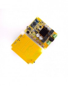
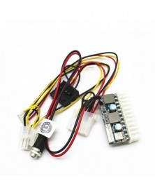
DC ATX 160W 24 Pin tápmodul kábel PICO-PSU DC-ATX tápmodul kábel DC csatlakozó POS géphez hálózati szerver mini
1 219 Ft 2 540 FtProduct Description
100% brand new and high quality
Input Voltage: DC 12V
Output ATX: Max 160W
Output Power: 84W
Standard 24pin ATX Power Connector
Power Efficiency: ≥ 92%
Operating temperature: 0℃ - 40℃
Storage temperature: -20℃ - 80℃
Size: 55×33×13mm/2.17×1.30×0.51in (Approx.)
PCB Size: 55×22mm/2.17×0.87in (Approx.)
DC 5.5*2.5 (16AWG): 300mm/11.81in
4-pin IDE female (18AWG): 240mm/9.45in
15-pin SATA (18AWG): 240mm/9.45in
CPU 4-pin (18AWG): 240mm/9.45in
4-pin IDE to 15-pin SATA (18AWG): 100mm/3.94in
Output characteristics:
Output Current 12V (11.4V~12.6V): 3A
Output Current 5V (4.75V~5.25V): 5A
Output Current 3.3V (3.14V~3.47V): 5A
Output Current 5VSB (4.75V~5.25V): 1A
Output Current -12V (-11.4V~-12.6V): 0.1A
Application:
Mini computer, all-in-one computer, POS machine, digital set top box, ITX case, network server,
advertisement machine, bank terminal, etc. -
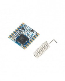
2db 868MHz szuper kis teljesítményű RF LoRa modul SX1276 chipes nagy távolságú kommunikációs vevő IOT adó SPI IOT
1 216 Ft 2 533 FtProduct Description
SX1276 Wireless Transceiver Module Lora 868Mhz Modulespread Spectrum Long-Range Wireless Communication LORA/GFSK
Module function
FSK / GFKS technology, LoRa (remote) spread spectrum technology
Half-duplex communication
Super anti-interference (channel rejection ratio: 56db)
High receiver sensitivity -139dbm.
ISM multi-band, do not need to apply the frequency of free use.
Multi-frequency optional, a variety of transmission rates. Can be used in FDMA and FM technology.
Intelligent reset, low-voltage monitoring, wake-up time, low-power mode, sleep mode
Low power receive current: 10-12mA
256-bit FIFO TX / RX
RSSI channel detection function
Transmission Mode: FIFO / Direct Mode (Recommended FIFO Packet Mode)
Configuration: AFC / Wake on Air / Low Power / Carrier Sense / FEC Error Correction / AEC Encryption
Ultra-long-distance transmission as far as 3KM open
Product Pictures -
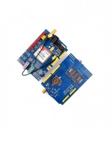
SIM900 GPRS/GSM Shield Fejlesztőkártya négysávos modul Arduino-kompatibilis
1 177 Ft 2 453 FtDescription
The GPRS Shield is based on SIM900 module from SIMCOM and compatible with and its clones. The GPRS Shield provides you a way to communicate using the GSM cell phone network. The shield allows you to achieve SMS, MMS, GPRS and Audio via UART by sending AT commands (GSM 07.07 ,07.05 and SIMCOM enhanced AT Commands). The shield also has the 12 GPIOs, 2 PWMs and an ADC of the SIM900 module(They are all 2V8 logic) present onboard.
Quad-Band 850 / 900/ 1800 / 1900 MHz - would work on GSM networks in all countries across the world.
GPRS multi-slot class 10/8
GPRS mobile station class B
Compliant to GSM phase 2/2
Class 4 (2 W @ 850 / 900 MHz)
Class 1 (1 W @ 1800 / 1900MHz)
Control via AT commands - Standard Commands: GSM 07.07 & 07.05 | Enhanced Commands: SIMCOM AT Commands.
Short Message Service - so that you can send small amounts of data over the network (ASCII or raw hexadecimal).
Embedded TCP/UDP stack - allows you to upload data to a web server.
RTC supported.
Selectable serial port.
Speaker and Headphone jacks
Low power consumption - 1.5mA(sleep mode)
Industrial Temperature Range - -40°C to 85 °C
Size:8.5x5.7x2cm(approx) -
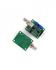
10 db/tétel LM393 3,5-24V feszültség-összehasonlító modul magas szintű kimeneti analóg komparátor vezérlés LED
1 073 Ft 2 235 FtProduct Description
1.Input Voltage:4.5-28V
2.Comparator Chip:LM393
3.Size:39.5*17mm
4.Application:for NTC thermosensitive temperature sensor,photosensitive sensor
5.Using Method:by reference voltage adjusting potentiometer to generate reference voltage,and compare voltage generated by sensor and divide resistor with reference voltage,achieving high/low level comparision result output -
Piros szín - DC 8 -25V TDA7492P 50W*2 kétcsatornás erősítő vezeték nélküli digitális Bluetooth 4.0 hangvevő
1 154 Ft 2 404 FtDescribe
Power Supply: 2.1 interface DC 8 ~ 25V power supply. It will work during the range.
Suitable Adapter: 5.5mm*2.1mm
Output impedance: 8 ohm best (can drive 4,6,8,16 ohm impedance speaker)The best speaker is 8 ohm
Audio input: stereo input various versions of the Bluetooth connection
Using CSR8635 Bluetooth chip, Bluetooth V4.0, high software compatibility
How to Pair:
First, you need to check voltage whether the voltage is during DC 8-25V power supply. 12V is the best.
After charging and booting, the section will automatically get into pairing mode, search display device name: “Aideepen.com Audio”
Then turn on the power, the Bluetooth Indicator flash, pairing the device when the red and blue flashes alternately. Please attention, If the Bluetooth connection is not available, please kindly ignore the “Aideepen Audio” Bluetooth, device is disconnected for 10 seconds, re-search for pairing. -
Szín: Bule - DC 8 -25V TDA7492P 50W*2 kétcsatornás erősítő vezeték nélküli digitális Bluetooth 4.0 audio vevő
1 154 Ft 2 404 FtDescribe
Power Supply: 2.1 interface DC 8 ~ 25V power supply. It will work during the range.
Suitable Adapter: 5.5mm*2.1mm
Output impedance: 8 ohm best (can drive 4,6,8,16 ohm impedance speaker)The best speaker is 8 ohm
Audio input: stereo input various versions of the Bluetooth connection
Using CSR8635 Bluetooth chip, Bluetooth V4.0, high software compatibility
How to Pair:
First, you need to check voltage whether the voltage is during DC 8-25V power supply. 12V is the best.
After charging and booting, the section will automatically get into pairing mode, search display device name: “Aideepen.com Audio”
Then turn on the power, the Bluetooth Indicator flash, pairing the device when the red and blue flashes alternately. Please attention, If the Bluetooth connection is not available, please kindly ignore the “Aideepen Audio” Bluetooth, device is disconnected for 10 seconds, re-search for pairing. -
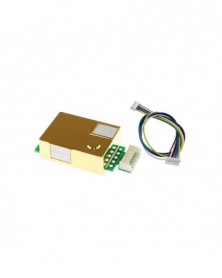
Szín: MH-Z19B - MH-Z19 MH-Z19B MH-Z19C infravörös CO2 érzékelő modul Szén-dioxid gáz érzékelő CO2 monitorhoz 0-5000
2 201 Ft 4 586 FtMH-Z19B
MH-Z19B carbon dioxide gas sensor (hereinafter referred to as the sensor) is a general-purpose smart small-scale sensor that uses non-dispersive infrared (NDIR) principle to detect the presence of CO2 in the air, with good selectivity and anaerobic Gas dependence, long life and other characteristics; built-in temperature compensation; at the same time with serial output, analog output and PWM output, easy to use. The sensor is a high-performance sensor that combines mature infrared absorption gas detection technology with precise optical path design and sophisticated circuit design.
Parameters:
Product model number: MH-Z19B
Gas Detection: Carbon Dioxide
Supply voltage: 4.5~5.5V DC
Average current: <20mA (@5V power supply)
Peak current: 150 mA (@5V supply)
Interface level: 3.3V (5V compatible)
Measurement range: 0~10000ppm can be selected within the range
Warm-up time: 3min
Response time: T90<120s
Working temperature: 0~50°C
Operating Humidity: 0 to 95% RH (non-condensing)
Characteristics:
Gas chamber with gold plating, waterproof and corrosion resistant
High sensitivity, low power consumption
Excellent stability
Temperature compensation, excellent linear output
Provides serial (UART), analog (DAC), PWM waveform output methods
long lasting
Water vapor interference, not poisoning
Application:
HVAC refrigeration equipment
Air quality monitoring equipment
Fresh air system
Air purification equipment
Smart home
SCHOOL
Vin: Power Positive (Vin)
GND: Negative Power Supply (GND)
Vo: Analog output
PWM: PWM
HD: HD (zero for school, low for more than 7 seconds)
Rx: UART(RXD) TTL Level Data Input
Tx: UART (TXD) TTL level data output
Pin 1: Analog Output Vo
Pin 2: None
Pin 3: Negative Power Supply (GND)
Pin 4: Positive Power Supply (Vin)
Pin 5: UART(RXD) TTL Level Data Input
Pin 6: UART (TXD) TTL Level Data Output
Pin 7: None
MH-Z19C
The MH-Z19C carbon dioxide gas sensor (hereinafter referred to as the sensor) is a general-purpose intelligent small sensor that uses the principle of non-dispersive infrared (NDIR) to detect the presence of C02 in the air. And other features; built-in temperature compensation: simultaneously has serial output, PWM output, easy to use. The sensor is a high-performance sensor made by closely combining mature infrared absorption gas detection technology with sophisticated optical circuit design and sophisticated circuit design.
Product parameters:
Detection gas: carbon dioxide
Power supply voltage: DC (5.0 ± 0.1) V
Average current: <40mA (@5V power supply)
Peak current: 125 to (@5V power supply)
Interface level: 3. 3v (compatible with 5v)
Measuring range: 400-5000PPM optional
Output signal: serial UART (TL level 3.3V)
Warm-up time: 1min
Response time: T90< 120s
Working temperature: -10-50degree
Working humidity: 0~95% RH (no condensation)
Pin description:
Vin: Power (in)
GND: power supply-(GND)
PWM: PWM
Hd: HD (zero calibration, low level is effective for more than 7 seconds)
Rx: UART (RXD) TTL level data input
Tx: UART (TXD) TTL level data output
Output method:
PWM output
Assume the measurement range is 400-2000ppm
CO2: Concentration output range: 400-2000ppm
Period: 1004ms±5%
High level output at the beginning of the cycle: 2ms (theoretical value)
Central period: 1000ms±5%
Low level output at the end of the period: 2ms (theoretical value)
Calculation formula for obtaining current CO2 concentration value by PWM: Cppm=2000X (TH-2ms)/(TH TL-4ms)
Cppm: CO2 concentration value calculated by the unit of ppm
TH: the time when the output is high level in one output cycle
TL: the time when the output is low in one output cycle
Serial output (UART)
Hardware connection, connect the sensor's Vin-GND-RXD-TXD to the user's 5V-GND-TXD-RXD. (User terminal must use TTL level)
Precautions:
1. In the process of welding, installation and use of the sensor, the gold-plated plastic cavity should be prevented from withstanding pressure in any direction.
2. If the sensor needs to be placed in a small space, this space should be well ventilated, especially the two diffusion windows should be in a well ventilated position.
3. The sensor should be far away from the heat source, and avoid direct sunlight or other heat radiation.
4. The sensor should be calibrated regularly, and the calibration period is recommended to be no more than 6 months.
5. Do not use the sensor for a long time in the environment with high dust density.
6. In order to ensure that the sensor can work normally, the power supply voltage must be maintained at (5.0 ± 0.1) VDC. The power supply current must not be less than 150mA
7. If it is not within this range, the sensor may be faulty, the output concentration of the sensor is low or the sensor cannot work normally.
8. When manually calibrating the zero point or sending the command to calibrate the main points, it must be stable
9. Work continuously for more than 20 minutes in a gas environment (400ppm).
10. The sensor is prohibited to use wave peak depth.
11. When welding with iron, set the temperature to (350±5) degree, early
12. The pick-up time must be less than 35.
13. When using the sensor, it is recommended that the customer use the method of inserting the solder bump to directly insert and remove the sensor for toilet maintenance. -
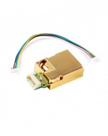
Szín: MH-Z19C - MH-Z19 MH-Z19B MH-Z19C infravörös CO2 érzékelő modul Szén-dioxid gáz érzékelő CO2 monitorhoz 0-5000
2 218 Ft 4 621 FtMH-Z19B
MH-Z19B carbon dioxide gas sensor (hereinafter referred to as the sensor) is a general-purpose smart small-scale sensor that uses non-dispersive infrared (NDIR) principle to detect the presence of CO2 in the air, with good selectivity and anaerobic Gas dependence, long life and other characteristics; built-in temperature compensation; at the same time with serial output, analog output and PWM output, easy to use. The sensor is a high-performance sensor that combines mature infrared absorption gas detection technology with precise optical path design and sophisticated circuit design.
Parameters:
Product model number: MH-Z19B
Gas Detection: Carbon Dioxide
Supply voltage: 4.5~5.5V DC
Average current: <20mA (@5V power supply)
Peak current: 150 mA (@5V supply)
Interface level: 3.3V (5V compatible)
Measurement range: 0~10000ppm can be selected within the range
Warm-up time: 3min
Response time: T90<120s
Working temperature: 0~50°C
Operating Humidity: 0 to 95% RH (non-condensing)
Characteristics:
Gas chamber with gold plating, waterproof and corrosion resistant
High sensitivity, low power consumption
Excellent stability
Temperature compensation, excellent linear output
Provides serial (UART), analog (DAC), PWM waveform output methods
long lasting
Water vapor interference, not poisoning
Application:
HVAC refrigeration equipment
Air quality monitoring equipment
Fresh air system
Air purification equipment
Smart home
SCHOOL
Vin: Power Positive (Vin)
GND: Negative Power Supply (GND)
Vo: Analog output
PWM: PWM
HD: HD (zero for school, low for more than 7 seconds)
Rx: UART(RXD) TTL Level Data Input
Tx: UART (TXD) TTL level data output
Pin 1: Analog Output Vo
Pin 2: None
Pin 3: Negative Power Supply (GND)
Pin 4: Positive Power Supply (Vin)
Pin 5: UART(RXD) TTL Level Data Input
Pin 6: UART (TXD) TTL Level Data Output
Pin 7: None
MH-Z19C
The MH-Z19C carbon dioxide gas sensor (hereinafter referred to as the sensor) is a general-purpose intelligent small sensor that uses the principle of non-dispersive infrared (NDIR) to detect the presence of C02 in the air. And other features; built-in temperature compensation: simultaneously has serial output, PWM output, easy to use. The sensor is a high-performance sensor made by closely combining mature infrared absorption gas detection technology with sophisticated optical circuit design and sophisticated circuit design.
Product parameters:
Detection gas: carbon dioxide
Power supply voltage: DC (5.0 ± 0.1) V
Average current: <40mA (@5V power supply)
Peak current: 125 to (@5V power supply)
Interface level: 3. 3v (compatible with 5v)
Measuring range: 400-5000PPM optional
Output signal: serial UART (TL level 3.3V)
Warm-up time: 1min
Response time: T90< 120s
Working temperature: -10-50degree
Working humidity: 0~95% RH (no condensation)
Pin description:
Vin: Power (in)
GND: power supply-(GND)
PWM: PWM
Hd: HD (zero calibration, low level is effective for more than 7 seconds)
Rx: UART (RXD) TTL level data input
Tx: UART (TXD) TTL level data output
Output method:
PWM output
Assume the measurement range is 400-2000ppm
CO2: Concentration output range: 400-2000ppm
Period: 1004ms±5%
High level output at the beginning of the cycle: 2ms (theoretical value)
Central period: 1000ms±5%
Low level output at the end of the period: 2ms (theoretical value)
Calculation formula for obtaining current CO2 concentration value by PWM: Cppm=2000X (TH-2ms)/(TH TL-4ms)
Cppm: CO2 concentration value calculated by the unit of ppm
TH: the time when the output is high level in one output cycle
TL: the time when the output is low in one output cycle
Serial output (UART)
Hardware connection, connect the sensor's Vin-GND-RXD-TXD to the user's 5V-GND-TXD-RXD. (User terminal must use TTL level)
Precautions:
1. In the process of welding, installation and use of the sensor, the gold-plated plastic cavity should be prevented from withstanding pressure in any direction.
2. If the sensor needs to be placed in a small space, this space should be well ventilated, especially the two diffusion windows should be in a well ventilated position.
3. The sensor should be far away from the heat source, and avoid direct sunlight or other heat radiation.
4. The sensor should be calibrated regularly, and the calibration period is recommended to be no more than 6 months.
5. Do not use the sensor for a long time in the environment with high dust density.
6. In order to ensure that the sensor can work normally, the power supply voltage must be maintained at (5.0 ± 0.1) VDC. The power supply current must not be less than 150mA
7. If it is not within this range, the sensor may be faulty, the output concentration of the sensor is low or the sensor cannot work normally.
8. When manually calibrating the zero point or sending the command to calibrate the main points, it must be stable
9. Work continuously for more than 20 minutes in a gas environment (400ppm).
10. The sensor is prohibited to use wave peak depth.
11. When welding with iron, set the temperature to (350±5) degree, early
12. The pick-up time must be less than 35.
13. When using the sensor, it is recommended that the customer use the method of inserting the solder bump to directly insert and remove the sensor for toilet maintenance. -
XH-M139 2.1 csatornás digitális teljesítményerősítő kártya 12V-24V széles feszültségű TPA3116D2 2*50W 100W
1 322 Ft 2 755 FtFeatures:
Adopts two high quality TPA3116D2 digital amplifier chips.
Sound quality is very good, high efficiency and amplifying power.
50W*2 100W 2.1 channels(left/right channel and subwoofer channel), high efficiency and low-heat.
Powered by DC 12-24V, wide input voltage.
User can adjust the volume by themselves easily.
Applicable speaker impedance: 4-8 ohm.
Just connect the power supply and loudspeaker box, enjoy the pure digital music!
Notice:
This amplifier board must be powered by DC power(DC12-24V), it's better to use high-performance switch power. Don't use transformer!
Specifications:
Supply Voltage: DC 12-24V
Chip: TPA3116*2
Channel Type: 3 Channels(Left Channel, Right Channel, Subwoofer)
Output Power: 50W*2 100W*1 Subwoofer
Output Match: 4-8 ohm
Audio Output: Terminals
Frequency Response Range: 14-100KHz
SNR: 100dB
Switching Frequency: 1.2MHz
PCB Board Size: 100 * 70 * 30mm / 3.94 * 2.75 * 1.18in (L * W * H)
Package Size: 13.5 * 11 * 5cm / 5.31 * 4.33 * 1.97in (L * W * H)
Package List:
1 * 2.1 Channel Audio Amplifier Board -
TDA7492P 50W 50W digitális erősítőkártya CSP8635 Bluetooth 4.0 Chip BT audio vevő erősítő kártya modul alkatrészei
1 111 Ft 2 315 FtProduct Description:
The four-stage gain switch (00, 01, 10, 11) can directly adjust the amplifier gain, which can drive low-resistance loads well and obtain greater power output.
specification:
Power supply: 2.1 interface, 8~24V DC power input;
Audio input: Bluetooth connection input, using CSR8635 Bluetooth 4.0 module, with high device compatibility;
AUX audio source input is convenient design, which can realize AUX&Bluetooth mixing output!
Output impedance: 8Ω (can drive 4, 6, 8, 16 ohm impedance speakers);
Output power: official nominal power 2*50W&6Ω;
How to use: Connect to the power supply and wait for 3 seconds until the blue and red LED flashes alternately. You can use your mobile phone or other Bluetooth transceiver to find the Bluetooth amplifier, and the mobile phone displays "SHAIBANG", just click to connect. With automatic connection function of device memory.
Button functions: play/pause, next song, previous song, volume up, volume down;
Color: PCB board red
Power amplifier board size: 82.1mmX50.5mmX18.8mm(L*W*H) -
SIM800 GSM GPRS modul STM32 SIM900A frissítőkártya GPS modul
1 281 Ft 2 668 FtDescription
SIM800 GSM GPRS module STM32 SIM900A upgrade board GPS module
A basic function
The SIM800 module is a GSM/GPRS module. The development board supports Unicom Mobile 2g/3g/4g card.
1. DC6-24v wide voltage power supply, which can facilitate the use of your system power supply. Onboard high-performance DC-DC power supply circuit, plus TVS protection, greatly improve the stability of the system
2. Support 3.3V/5V TTL level control, which is convenient for various commonly used single-chip microcomputers.
The modules are listed in TX/RX/GND, easy to use
3. With standard serial interface, it is convenient for host computer to control or debug
4 With earphone and microphone interface, it is convenient to test the GSM voice call function
5. With SIM card ESD protection chip, electrostatic protection when the SIM card is inserted and unplugged
6 SIM800 all available pins, convenient for you to develop various SIM800 applications
7. With RTC backup battery
8. With NET_STA light, it is convenient to check the current status of SIM800.
9 board size 83mm*54mm
Shipping list: SIM800 GSM GPRS module * 1 -
XH-M139 TDA3116D2 digitális végerősítő kártya 2*80W 100W mélynyomó sztereó audio hangszóró modul
1 288 Ft 2 683 FtSpecifications:
Product name:2.1 channel audio amplifier
Chip Select:TPA3116D2*2
Supply voltage:Recommended DC24V (range 12-26V 3A)
Output power:80W*2(MAX) 100W*1 (Subwoofer)
Output Impedance:4-8 ohms
Frequency range:14-100Khz
SNR:100db
Number of channels:3 (left channel,right channel,subwoofer)
Switch frequency:1.2MHz -
2x100W XH-M190 TPA3116 D2 kétcsatornás digitális audioerősítő lap TPA3116D2 kétcsatornás modul 100W 100W 12-24V
1 177 Ft 2 453 FtProduct introduction:
This power amplifier board uses TI imported TPA3116D2 as the core. The official data sheet is 50W*2. Engineers review the data and combine their own experience to develop a 50W*2 dual-core technology by bridging. The theory can reach 100W*2.
Because the chip is a digital chip, the efficiency is extremely high and can reach more than 90% , so it has the advantages of high power and low heat. It is recommended to use DC 12-24V 100W or more switching power supply for power supply. This board is a finished board and can be used by hand. You can check the new experience brought by pure digital music with the speaker!
Product parameters:
Chip selection: TPA3116
Input power: DC12-24V
Output power: 2*100W
Input resistance: 51K*2
Output matching: 4-8 ohms
Frequency response range: 14-100Kz
Sex to noise ratio: 100db
Output channels: 2 (left channel right channel)
Appearance size: 105*65*23mm -
TDA7492 Bluetooth teljesítményerősítő kártya CSR8635 chip Bluetooth CSR4.0 audio vevő digitális teljesítményerősítő
1 115 Ft 2 323 FtDescribe
After the power is turned on, it will automatically enter the pairing mode, search and display the device name: SANWU Audio (customized device name can be provided for bulk demand)
Power supply: 2.1 interface DC 8~25V power supply (input with reverse polarity protection)
Audio input: various versions of Bluetooth connection stereo input, using CSR8635 Bluetooth chip, Bluetooth V4.0, extremely high software compatibility
Output impedance: 8 ohms (can drive 4, 6, 8, 16 ohm impedance speakers)
Output power: Join the pre-stage 5532 output power is 25W 25W
The DIP switch can be more convenient to directly adjust the gain of the power amplifier of the later stage, and better promote the loudspeaker with larger damping. -
MC33886 motoros meghajtó modul 4 kimeneti robot Intelligens autómotor léptetőmotor
1 010 Ft 2 104 FtFeatures:
High-current low-impedance motor drive
Short circuit protection, under-voltage protection, over temperature protection functions.
compact, easy to use.
Description:
The driver board is a high-current motor driver board, which uses the driver chip mc33886. The driver board can drive two motors at the same time, the output current can reach 5A, and can realize real-time control functions such as motor PWM speed regulation, forward and reverse rotation and braking. . And has over-current, under-voltage and over-temperature automatic protection, as well as fault status prompt function
Specifications:
Color: blue
Size: 100*80mm
Working voltage: 6.5V~24V power supply
Internal resistance: 140 milliohms
PWM frequency: <10KHZ
Drive high current: 5A
Temperature range: -40 ° C ~ 125 ° C
Package Included:
1x MC33886 Motor Drive Module
Notice:
1.All the pictures in our store are 100% taken from the original products. Because of light in different environments, different display screens, and other reasons, probably there will be a little chromatic aberration between picture and product.
2.Due to the manual measurement and different measurement methods, please allow1-3mm deviation.Thanks! -
Bluetooth hangszóró új tábla Bluetooth digitális teljesítményerősítő vezeték nélküli vételi
960 Ft 2 000 FtDescription
he materials and workmanship are good, and the sound quality is very good. With a power amplifier, it can directly drive 4 ohm ~ 16 ohm speaker speakers, v4.0 Bluetooth, backward compatible with all Bluetooth versions, full power output 2x10W
Product parameters:
Three buttons
Power supply voltage: 12VDC (<15VDC)
Power supply interface: 2.1/5.5 DC seat
Power supply current: not less than 2A power supply (recommended)
Audio input method: Bluetooth receiver V4.0
Audio output mode: terminal block
Number of channels: two-channel stereo -
Szín: SIM900A - SIM900A SIM800A V4.0 készlet vezeték nélküli bővítőmodul GSM GPRS kártyaantenna
950 Ft 1 980 FtDescription:
SIM800A
1.Wide voltage power supply: 5-18V DC power supply
2.Power on automatically
3.Power can be controlled: the module power supply control pin through the control, high-level power supply, low power
4.Serial TTL and RS232: The module can be controlled by serial TTL or RS232 level
5.Audio interface: audio input and audio output interface pin through the pin
6.TTS and Bluetooth
SIM900A
The onboard two set power supply interface VCC5 5V power supply, VCC4 interface, 3.5--4.5V power supply, optional power on self starting (default) and control start.
The onboard SMA (default) and IPXmini antenna interface, SIM900A interface reserved reset.
The size of the module is 49*50, all the new and original device.
The computer can give early computer debugging USB module power supply, a very large amount of data under the condition of the recommended current more than 1A. Standby dozens of MA data can be set to provide dormancy, dormancy of 10MA low power. Support 2, mobile phone 3,4G card.
The serial port circuit: support for 3.3V single chip microcomputer. TTL serial port support
3.3 and 5V single chip microcomputer.
The SIM card circuit to increase the SMF05C ESD chip.
Antenna circuit: guarantee short and straight, so as to ensure the signal strength.
PCB display screen printing mark: each interface, convenient development two times, the SIM900/A hardware is completely follow the design when the design manual.
Two power supply interface: VCC5, 5V DC above 1A. Computer 5V power supply can be early computer USB. DC long data circuit over larger recommended 5V1A. VCC4, 3.5--4.5V power supply, ibid., suitable for lithium battery.
Control pin all leads.
A TTL level, compatible with 3.3V and 5V.
The two antenna interface, the default SMA straight head, connector for IPXmini antenna.
One way of speech interface, the way Mike interface.
The control interface of each pin description:
GND - GND
SIMR SIM900A RXD, TTL level, can not be directly connected to the 232 level
SIMT SIM900A TXD, TTL level, can not be directly connected to the 232 level
RST - SIM900A reset, active low
VCC_MCU when the SIM900A module and 5V TTL level communication, this pin is connected to DC 5V; when the level of communication of SIM900A and 3.3V TTL, this pin is connected to DC 3.3V.
VCC5----DC 5V input.
VCC4------DC3.5--4.5 input
Onboard Resources:
Serial port circuit(with protection)
Antenna interface circuit(SMA bend female port)
SIM card circuit(flip SIM slot)
4*3.5 fixture hole 4pcs
SIM900A serial port output terminal