Kereskedelmi, irodai és ipari
-
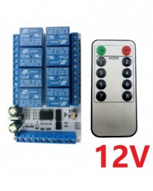
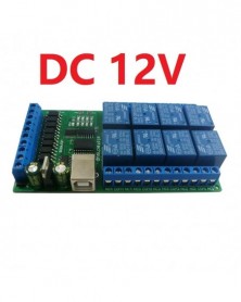
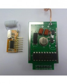
Szín: 12V készlet - 8 csatornás DC 5V 12V Többfunkciós VS1838 IR infravörös vezérlés Késleltetés relé modul Flip
1 295 Ft 2 642 FtProduct Name: 8ch DC 5V 12V Multi-function VS1838 IR infrared control Delay Relay Module Flip-Flop Latch Bistable Self-locking Interlock Latch Switch Board
Package inlcuded:
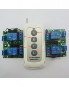
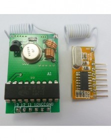
1 PCS 8 Channel IR remote control
1 PCS 8 Channel IR Relay Control
Description:
Product Specifications:
1 Operating Voltage : DC 12V/5V
2 Operating Current(DC 12V) : Standby current 8-9MA, 1 relay open 37MA, 2 relays open 66MA, 3 relays open 94MA, 4 relays open 122MA, 5 relays open 150MA, 6 relays open 178MA, 7 relays open 205MA, 8 relays open 231MA
3 ''Momentary'' ''Self-locking'' ''Interlock'' ''Delay'' Four functional modes
4 Infrared receiver: VS1838(Or compatible IC)
5 Infrared remote control: NEC coding
6 Working distance: 8-15 meters (receiver sensitivity ≥0.5mW / m2)
7 Input control pins 8 ,5V TTL level ,NPN trigger, 0.2-2 second low pulse
8 Size: 99 x 62 x 20 mm
9 Weight : 118g
10 Relay maximum load capacity: DC 1-110V/5A; AC 85-265V/6A
Product Features:
8 channel Multi-function infrared controller, each channel independently triggered independent delay, do not interfere with each other.
4 kinds of Functional mode: Non-locking (Momentary );Delay(2/10/60/600/3600seconds); Self-locking (Toggle); Inter-locking (Latch), The function mode and delay time are selected by the Solder pad.
Low pulse trigger(Connect to the power supply GND via the trigger button or low level control via the MCU IO port)
Glossary:
NO : Relay normally open contact
COM : Relay common contact
NC : Relay normally closed contact
Relay open: COM connect NO.
Relay close: COM disconnect NO.
Momentary : Press the remote control button (or trigger input port), Relay open, return to Close after 0.5 second;
Self-locking : Press the remote control button (or trigger input port), Relay open, Press again, port Relay close, and so on;
Latched : Enter the Channel 1 Latched command, port 1 Relay open, port 2-8 Relay close. Enter the Channel 2 Latched command , port 2 Relay open, port 1/3-8 Relay close
Delay : Enter the Delay command, Relay open, delay of 2/10/60/600/3600 seconds)after, Relay close;
Function mode selection by shorting three pads M2 1 0
Infrared remote control Technical Parameters
Transmission / coding: NEC coding
IRED: Infrared
Wavelength: 950nm
Power supply: DC 3V
Working voltage: 2.2-3.4V
Working current: ≥10mA
Static current: ≥1uA
Transmit power: 90 mW / sr typ.
Working distance: 8-15 meters (receiver sensitivity ≥0.5mW / m2)
Frequency: 38 kHz
Battery: CR2025(Not included)
Operating temperature: 55 ~ -45 or specific specifications
Storage temperature: -25 ~ 55 or specific specifications
Size : 85 x 40 x 7mm
Weight : 11g -
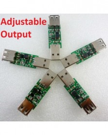
5x 7 W USB - USB 5 V - 9 V 12 V 15 V inverter Step Up Boost DC DC átalakító UPS modul LED Moter rf vezérlőhöz Napelemes
1 737 Ft 3 544 Ft
Note: Adjustable resistors (potentiometers) are components that are easily damaged. Use a suitable screwdriver to slowly rotate. Click here to buy a screwdriver.
Product Name:5x 7W USB to USB 5V to 9V 12V 15V Inverter Step Up Boost DC DC Converter UPS Module for LED Moter rf controller Solar Charger
Packing list :
5 pcs 7W USB to USB Adjustable Output Step UP Converter(5V TO 6-15.5V)
Description:
Input voltage 3~6V, output 6-15.5V
Maximum input current : 1.4A
Long-term work Current : 1.1A
Conversion efficiency : 80-91%
Input : USB Male Interface, DC 3-6V;
Ouput : USB Fem ale Interface , DC 6-15.5V;
If input dc 5v,output 6-15.5V Adjustable
Power : Maximum 7W;
DC-DC Boost module working frequency 1.0MHZ.
Operating ambient temperature : -40~ 85 Degrees Celsius .
Size 56mm x 16mm
Weight : about 6g(light)
Attention :
This is a DC-DC voltage converter module,Must be noted when using:
1 Input voltage can not be greater than the maximum input range
2 Output power can not be greater than the maximum load for a long time
3 Input power must be greater than the output power, because the power consumption of the module itself
Q & A:
Q : Why output voltage is less than the nominal voltage
A : Input power supply power is too low.Test the input voltage with a multimeter,a t this time of the input voltage is very low
Application :
Packing list does not include USB Charger/routers/mobile power
Modify Parameter Description:
1.4A current limiting resistor,Remove the resistance, the maximum input current can reach 2A.
But IC have "Over Temperature Protection" Function.It will turn off the power MOSFET automatically when the internal junction temperature is over 150 Degrees Celsius. The power MOSFET wake up when the junction emperature drops 30 Degrees Celsius under the OTP threshold temperature
The master chip is FP6291(Made in Taiwan) -
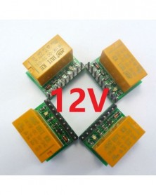
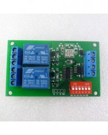
4db szuper kis DC 12V DPDT relékártya modul HK19F PCB kártya sztereó videó PLC Motor 18650 3d nyomtatóhoz
665 Ft 1 358 FtTypical applications
Automotive electronics
Audio and video equipment
UNO MEGA2560 DUE PIC AVR raspberry pi
Motor Polarity reversal
LED
Smart Home
Emergency lighting
Arduiuo uno/mega2560 Code
//******************************************************//
const int DPDT_control = 2; // the number of the DPDT_control pin
void setup() {
// initialize the DPDT_control pin as an output:
pinMode(DPDT_control, OUTPUT);
}
void loop() {
digitalWrite(DPDT_control, HIGH);//DTDT relay activation
delay(1000);
digitalWrite(DPDT_control, LOW);//DTDT relay inactive
delay(1000);
}
//******************************************************//
Product Name : 4pcs Super small DC 12V DPDT Relay Board Module HK19F PCB Board for Stereo video PLC Motor 18650 3d printer
Packing list:
4 PCS DR21C01 1 Channel DC 12V DPDT Relay Module
Description:
DR21C01 12VDC 1 Channel DPDT Relay Board
Operating Voltage : DC 12V
Operating Current(Relay ON): 15MA
Standby Current(Relay OFF) : <1MA
Input control signal voltage:
0V - 0.6V Low stage (relay is OFF),
0.6V – 2.4V (unknown state).
2.4V - 24V High state (relay is ON).
Input control signal high state current:
2.4V: 0.15mA
5V: 0.4mA
12V: 1.2mA
20V: 2mA
Relay Load : 1A 125VAC;2A 30VDC
Size : 22.86x18x14
Weight :7g
Schematic:
-
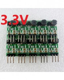
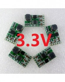
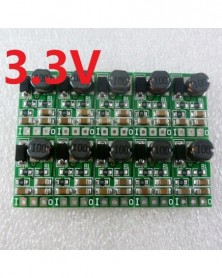
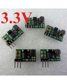
10db DC DC Step-Down Buck átalakító 5-40V-ról 3,3V-ra feszültségszabályozó modul Arduino Pro mini kenyérsütőlaphoz
1 303 Ft 2 659 Ft
Product Name : 10pcs DC DC Step-Down Buck Converter 5-40V to 3.3V Voltage Regulator Module for Arduiuo Pro mini breadboard
Packing list:
10 PCS DD4012SA_3V3 5V-40V to 3.3V DC DC Step Down Converter Module
Description:
Input voltage 4.8~40V,output 3.3V
Maximum output current 1A
DC-DC Step-Down Converter module working frequency 550KHz. efficiency is 76-90% .
Quiescent current: about 1.6MA
Overtemperature shutdown, input under-voltage protection, BS-voltage protection, and short circuit protection.
2.54mm pin pitch, Arduiuo UNO MEGA2560 Breadboard MCU Development Board friendly
Excluding Pin Size 18.3mm x 10.2mm x 6.7mm( small)
Weight : about 1.3g(Very light)
Attention :
This is a DC-DC voltage converter module,Must be noted when using:
1 Input voltage can not be greater than the maximum input range
2 Output power can not be greater than the maximum load for a long time
3 Input power must be greater than the output power, because the power consumption of the module itself
Applications:
3.3V MCU ARM CPU FPGA/CPLD
12V 6V 5V TO 3.3V lithium battery-powered systems
3.3V Motor
WIFI esp8266 Module
CCTV camera
Wireless Module:Nrf24l01 CC1101 CC2500 CC2530 Zigbee
Smart home / home automation
Distributed Power Systems
Battery Charger
Pre-Regulator for Linear Regulators
replace AMS1117-3.3 LM1117-3.3 1117 LDO
nodemcu esp8266 ds18b20 dht22 nrf24l01
-
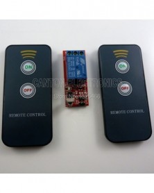
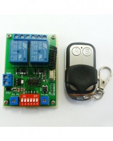
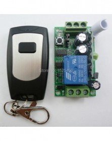
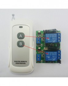
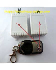
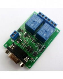
DC 12V 1CH IR infravörös távirányító kapcsoló relé kártya
1 053 Ft 2 148 FtProduct Name: DC 12V IR Infrared Remote Control Switch Relay Board Self-locking Toggle Controller replace 315M 433M 2.4G RF RC Wireless Module
Packing list:
1 PCS 1 channel Self-locking (Toggle) IR Receiver Controller;
2 PCS ON/OFF 2 button Infrared Remote Controller(Use CR2025 batteries ,NOTE : Batteries not included);
Description:
1 channel Self-locking (Toggle) IR Receiver Controller:
Operating voltage: DC 12V (voltage range : 9-13V)
Operating Mode : Self-locking (Toggle) ,Press Infrared Remote Controller "ON" button relay "NO" connected "COM", press Infrared Remote Controller "OFF" button relay "NO" and "COM" Disconnect
Size:50*20*20(MM)
Note : This IR receiver can only fit we offer IR remote control,the other IR remote control can not control this IR receiver
ON/OFF 2 button Infrared Remote Controller:
Using UPD6122 chip ,NEC encoding format
User code :0x00FF
Key value : "ON" Button is 40;"OFF" Button is 19
Frequency : 38K
Battery powered : CR2025(NOTE : Batteries not included)
Size : 86*40*6(MM) -
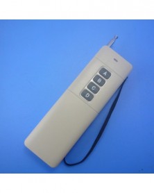
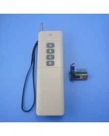
4 gombos nagy teljesítményű DC9V EV1527 Fix kódú távirányító
1 352 Ft 2 760 FtBelow item is powered by Canton-electronics Ltd .
Qty : 1 pcs4Button Fixed code remote ;
Features / Specifications :
1.4buttons;
2. High stability, SMT chip, frequency stabilization SAW, ultra-high-frequency transistor;
3: Large power;
Technical Data :
Transmitter Module No.: TB425;
Power supply : DC9V 6F22 battery (not included ) , .
Oscillation mode: SAW resonator;
Modulation mode:ASK/OOK AM ;
Operating frequency:433.92MHZ ;
Encoding format: EV1527 ;
RC Resistance : 330K;
Standby current: 0mA
Working current:> 80mA
Transfer rate: <10Kbps
Operating temperature: -10 ~ 70
Size: 136 * 42.2 * 25mm
power switch: the remote control can be turned off when not in use for power saving.
Remote distance
We are talking about remote control distance transmitter / receiver module to work alone, and are connected with one quarter of the wavelength of the metal antenna, and in a vertical state operation at rated conditions in open ground straight line measured maximum distance decoding, general , a high-power transmitter module straight road in the city a distance of 1 kilometer. Since the work within the UHF band electromagnetic wave propagation along a straight line, an obstacle will be a drastic attenuation, remote control distance shortened significantly, it should be used to avoid obstacles, or try to stand tall antenna.
-
5x 3,5A DC 5V-24V-3.3V DC-DC Step-Down Buck Converter szabályozó modul az esp8266 Wifi Bluetooth-kompatibilis STM32 ARM
1 298 Ft 2 648 Ft
Product Name : 5x 3.5A DC 5V-24V to 3.3V DC-DC Step-Down Buck Converter Regulator Module for esp8266 Wifi Bluetooth STM32 ARM Board
Packing list:
5 PCS DD2712SA_3V3 3.5A 4.5V-27V to 3.3V DC DC Buck Converter Module
Description:
Input voltage 4.5~27V,output 3.3V
Maximum output current 2.5A,Short time maximum output current 3.5A
DC-DC Step-Down Converter module working frequency 900KHz. efficiency is 77-92% .
Quiescent current: about 250uA
Overtemperature shutdown, Under-Voltage Lockout (UVLO), BS-voltage protection, and short circuit protection.
Operating Temperature :–20°C to 85°C
Size : 25 x 15 x 6.3mm
Weight : 2.4g
Attention :
This is a DC-DC voltage converter module,Must be noted when using:
1 Input voltage can not be greater than the maximum input range
2 Output power can not be greater than the maximum load for a long time
3 Input power must be greater than the output power, because the power consumption of the module itself
Applications:
Battery Powered Systems
High Voltage Power Conversion
Industrial Power Systems
Distributed Power Systems
3V MCU ARM CPU FPGA/CPLD
12V 5V TO 3.3V lithium battery-powered systems
3.3V MotorToy
WIFI esp8266 Module
CCTV camera
Wireless Module:Nrf24l01 CC1101 CC2500 CC2530 Zigbee
Smart home / home automation
Distributed Power Systems
Battery Charger
Pre-Regulator for Linear Regulators
FM radio
Battery powered equipment
Audio amplifier
-
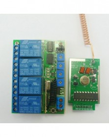
433M DC 12V 4C időzítő RF vezeték nélküli vezérlő késleltetés relé Tanulási kód kapcsoló EV1527 PT2262 ASK OOK
1 086 Ft 2 217 FtMatching Keyfob: Click here
Typical applications:
DC 12V Home lighting system
Remote control switch
Smart Home / Home Automation
LED lighting
Fluorescent lamp
DC 12 DC Motor,RS360
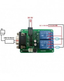
Wiring Diagram 1:
DC 12V control circuit,Wiring diagram below. "LOAD" may be LED lights, fans, motors and other DC 12V
Wiring Diagram 2:
DC 1-110V OR AC 85-265V control circuit,Wiring diagram below(Note:If not DC 12V load, need another DC 12V power supply). "LOAD" may be LED lights, fans, motors and other DC AC equipment
Wiring Diagram 3:
All kinds of motor reversing control: DC 1-110V or AC 85-265V DC/AC Motor
Product Name : DC 12V Multifunction Wireless Controller Timer Delay Relay Learning code for EV1527 PT2262 ASK OOK Remote control
Packing list:
1 PCS 433M DC 12V 4 Channel Multifunction Wireless Controller
Features:
1 Operating voltage : DC 12V
2 Operating Current: Standby current (all relays closed) 15MA, 1 relay open 42MA, 2 relays open 62MA, 3 relays open 94MA, 4 relays open 121MA
3 Operating frequency: 433.92M;
4 Receiver sensitivity : -108dBm
5 Decode : learning code, can be adapted EV1527 / PT2262(Click here)and compatible remote control, you can store up to 8 remote control
6 Work mode : Non-locking (Momentary is defult),Self-locking (Toggle),Inter-locking (Latch), Delay; Delay adjustable from 0.1 to 100 seconds, 0.1 seconds Resolution.
7 Size(Including housing)75*54*28mm
8 Weight: 77g
9 Relay Maximum load(Recommended<5A):10A/250VAC,10A/125VAC,10A/30VDC, 10A/28VDC ,10A/12VDC
Advantage :
1: Receiver Mother board have a learning key , if the remote is lost , must buy EV1527 OR Pt2262 remotes to re-learn;
Download information from the following link(Cannot copy, keyboard input url ,Case sensitive)
Work mode
Delay mode user guide :
1 In delay mode(Mode 3),with a suitable screwdriver and gently rotating adjustable resistance;Clockwise, increasing delay,Counter-clockwise, the delay is reduced
2 Delay adjustable from 0.1 to 100 seconds, 0.1 seconds Resolution.
Glossary :
NO : Relay normally open contact
COM : Relay common contact
NC : Relay normally closed contact
Open : NO connection COM, NC disconnect COM
Close : NO disconnect COM, NC connection COM
Momentary : Press the Transmitter button A, the receiver Channel 1 is Open, release button A; the receiver Channel 1 is Close, the same as B ,Every Channel is Independent ;
Toggle : Press transmitter button A for 1 time , the receiver Channel 1 is Open, press button A again, the receiver Channel 1 is Close, the same as B. Every Channel is Independent ;
Latched : Press transmitter button A, the receiver Channel 1 is Open, the Channel 2 is Close.
Press transmitter button B, the receiver Channel 2 is Open, the Channel 1 is Close.
Delay : Press the Transmitter button A, the receiver Channel 1 is Open,After a set time delay, the receiver Channel 1 is Close, the same as B ,Every Channel is Independent;
If during the delay, press the button of Transmitter, delay start again; if the delay period, press and hold the button of Transmitter 3-4 seconds, the receiver controller stops the delay, the relay Close
Adapter remote control (learning remote control):
Under normal operating mode, LED will be lit, when receives a valid remote control (EV1527 / PT2262) button values, LED flashes
Clean code: press the button and held down, LED off, LED will light about 8 seconds later, clean code is completed (Note: After performing clean code previously stored remote control value does not exist)
Step 1 (into the learning mode): Press the button (about 1 second), LED off;
Step 2 (adapter channel 1): Then press the first button on the remote control, LED flashes four times off, then learning the first button value
Step 3 (Adaptation Channel 2): Then press the second button on the remote control, LED flashes four times brighter, then learned two key values
Step 4 (Adaptation Channel 3): Then press the third button on the remote control, LED flashes four times brighter, then learned two key values
Step 5 (Adaptation Channel 4): Then press the fourth button on the remote control, LED flashes four times brighter, then learned two key values
-
10db DC 5V 6V 9V 12V – 3.3V Step-Down Buck DC-DC Converte tápegység a CC2530 Zigbee Nrf24l01 CC1101 vezeték nélküli
1 299 Ft 2 652 Ft
Product Name : 10pcs DC 5V 6V 9V 12V to 3.3V Step-Down Buck DC-DC Converte Power Supply for CC2530 Zigbee Nrf24l01 CC1101 Wireless Module
Packing list:
10 PCS DD4012SB_3V3 4.8V-40V to 3.3V DC DC Buck Converter Module
Description:
Input voltage 4.8~40V,output 3.3V
Maximum output current 1A
DC-DC Step-Down Converter module working frequency 550KHz. efficiency is 76-90% .
Quiescent current: about 1.5MA
Overtemperature shutdown, input under-voltage protection, BS-voltage protection, and short circuit protection.
2.54mm pin pitch, Arduiuo UNO MEGA2560 Breadboard MCU Development Board friendly
Size 18.3mm x 10.2mm x 6.7mm( small)
Weight : about 1.1g(Very light)
Attention :
This is a DC-DC voltage converter module,Must be noted when using:
1 Input voltage can not be greater than the maximum input range
2 Output power can not be greater than the maximum load for a long time
3 Input power must be greater than the output power, because the power consumption of the module itself
Applications:
3.3V MCU ARM CPU FPGA/CPLD
12V 5V TO 3.3V lithium battery-powered systems
3.3V Motor Toy
WIFI esp8266 HC-12 Bluetooth Module
CCTV camera
Wireless Module:Nrf24l01 CC1101 CC2500 CC2530 Zigbee
Smart home / home automation
Distributed Power Systems
Battery Charger
Pre-Regulator for Linear Regulators
FM radio
Battery powered equipment
Audio amplifier
-
EPM240 ALTERA Core FPGA CPLD fejlesztés Core Board JTAG és USB Blaster letöltés
2 574 Ft 5 253 Ft
Title : EPM240 ALTERA Core FPGA CPLD Development Core Board JTAG & USB Blaster Download
Module No.: RT379
Package inlcuded:
1 PCS EPM240 FPGA core board;
1 PCS High speed Altera USB Blaster;
1 PCS 10-Pin Flex Cable X 1;
Altera USB Blaster :
Packing list:
High Speed Altera USB Blaster;
10-Pin Flex Cable X 1;
USB wire X 1
Accessories :
Feature :
1. Using the perfect solution, download the fastest, most stable performance.
2. Support all ALTERA FPGA / CPLD chip.
3.AS download without secondary swap operation can be downloaded directly to run the program.
System configuration:
1, Windows XP, Windows Vista, Windows7 , USB interface;
2, all Quartus II Software version;
.''>1. SignalTap II ,!''>Stable support SignalTap II embedded logic analyzer function, the data will never catch caught mess!
.''>2. ALTERA''>ALTERA company supports a full range of devices. ,! ''>Absolutely the whole series, do not worry about a device does not support!
:MAX3000 MAX7000 MAX9000 MAXII ''>CPLD: MAX3000, MAX7000, MAX9000 and MAXII etc.
:Stratix StratixIIStratxIIICycloneCycloneIICycloneIIICycloneIVACEX1KAPEX20KFLEX10K ''>FPGA: Stratix, StratixII, StratxIII, Cyclone, CycloneII, CycloneIII, CycloneIV, ACEX1K, APEX20K and FLEX10K etc
:EPCS1EPCS4EPCS16EPCS64 ''>Active Serial Device: EPCS1, EPCS4, EPCS16, EPCS64 etc.
:EPC1EPC4 ''>Enhanced configuration devices: EPC1, EPC4 like.
.''>3. :ASPSJTAG; ''>Supports three download mode: AS, PS and JTAG;
.''>4. Nios II ,Rev.C!''>Communication and debugging support and Nios II embedded soft core processor in the system, Rev.C latest firmware! ; ''>;
.''>5. :ByteBlasterII6; ''>Speed: than conventional parallel port download cable ByteBlasterII 6 times faster;
.''>6. :USBB,,1 ''>Easy to use: USBB type side port for easy connection, a two-color status indicator makes debugging more handy.
.''>7. :,ByteblasterMVByteblasterII,,USB, ''>Must: present laptop has almost eliminated the parallel port, so common was ByteblasterMV and ByteblasterII download cable have can not be used in a notebook, so for notebook users, choose USB download cable that is convenient, it is a must.
.''>8. ALTERA USB Blaster ,ALTERA ''>Fully compatible with ALTERA USB Blaster, use, functionality and performance are consistent and ALTERA original download cable.
This product is the latest version of firmware for the official Rev.C! Perfect NiosII system debugging support jtag_uart,
JTAG
AS
PS
1 pcs EPM240 core Board;
Description:
Onboard EPM240T100C5N chip
50Mhz Active crystal
All pins from CPLD are Labelled and available onboard
Altera Official standards JTAG Interface
Two 5V 3.3V output to provide power for the peripheral
A Independent button for test core board
Two independent LED lights for test core board
Size : 9cm X 6cm (9:6 is Golden ratio )
PCB Board 3D View :
-
433,92M DC 12V 2Ch többfunkciós vezeték nélküli vezérlő időzítő késleltetés relé RF kapcsoló & EV1527 ASK OOK
1 365 Ft 2 785 FtWork mode
Typical applications:
DC 12V Home lighting system
Garage Door
Elevators
Motor reversing control
Remote control switch
Smart Home / Home Automation
LED lighting
Fluorescent lamp
DC 12 DC Motor,RS360
Wiring Diagram 1:
DC 12V control circuit,Wiring diagram below. "LOAD" may be LED lights, fans, motors and other DC 12V
Wiring Diagram 2:
DC 1-48V OR AC 85-265V control circuit,Wiring diagram below(Note:If not DC 12V load, need another DC 12V power supply). "LOAD" may be LED lights, fans, motors and other DC AC equipment
Product Name : 433.92M DC 12V 2Ch Multifunction Wireless Controller Timer Delay Relay RF Switch & EV1527 ASK OOK Remote control
Packing list:
1 PCS 433M DC 12V 2 Channel Multifunction Wireless Controller
1 PCS 433M Large Power 2 Button SC 2262 Remote Control (USE 12V 27A battery,Batteries not included)
Technical indicators:
Operating voltage: DC 9-13V (recommended DC 12V);5V version can be customized
Operating Current: All relays close,about 14MA; one relay open,about 43MA;two relay open,about 71MA
Receiver sensitivity :-108dB;
Work mode : Non-locking (Momentary is defult),Self-locking (Toggle),Inter-locking (Latch), Delay;Each channel independently set the Work mode; 500,000 seconds maximum delay
Size(Including housing)75*54*28mm
Learning function (can works with EV1527 and PT2262 remote, can store 16 pcs different code remote );
Max load : 500W;
Normally, we would adapter remote control and receiver.
If the item you received has not been adapted Or you need to add accessories, Please follow the instructions below
Learning method and steps:
Under normal operating mode, LED will be lit, when receives a valid remote control (EV1527 / PT2262) button values, LED flashes
Clean code: press the button and held down, LED off, LED will light about 8 seconds later, clean code is completed (Note: After performing clean code previously stored remote control value does not exist)
Step 1 (into the learning mode): Press the button (about 1 second), LED off;
Step 2 (adapter channel 1): Then press the first button on the remote control, LED flashes four times off, then learning the first button value
Step 3 (Adaptation Channel 2): Then press the second button on the remote control, LED flashes four times brighter, then learned two key values
Use more details, please click here!
433M 2 Button EV1527 Remote Control:
Power supply : 12V 27A battery replacable .(This remote doesnot have a battery , Please buy in your local market )
Operating current: ≤ 12mA ;
Oscillation mode: SAW resonator ;
Oscillation resistor : 330K
Modulation mode: ASK OOK ;
Operating frequency: 433.92MHz ;
Frequency dev iation: ±0.2MHz ;
Encoding format: Million Group Code ( EV1527 ) ;
Transmit power: 10 mW.
Data Rate : 50~60KHZ;
-
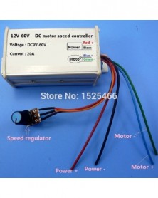
12V 24V 48V 20A PWM DC motor fordulatszám vezérlő meghajtó kefe nélküli NE555 25KHz JGB37-520 RS360 RS-360 370 380 R3157
1 179 Ft 2 406 FtProduct Name: 12V 24V 48V 20A PWM DC Motor Speed Controller Driver Brushless NE555 25KHz for JGB37-520 RS360 RS-360 370 380 R3157 GW80170 Pump
Packing list:
1 pcs 9-60V 20A DC Motor Speed Controller;
Description:
Operating voltage: DC 9V-60V
Output Current: 0 to 20A.
Output Power:0-1200W
PWM Frequency:25KHz.
Speed range: 0-100%
Speed principle : Adjust the current
Shell material : Aluminum Alloy
Size (L*W*H):84mm*52mm*36mm
Mounting holes center distance : 104mm
Typical applications:
DC 9V 12V 18V 24V 36V 48V 60V DC Motor Speed Controller
Motor speed control and regulation in RC models, fans and more
Small pump control, such as RS-360 motor
Temperature control in devices such as soldering irons
Brightness control of DC light bulbs
DC Motror JGB37-520 JGB37-550 RS-360 370 380 R3157 GW80170
Wiring Example: -
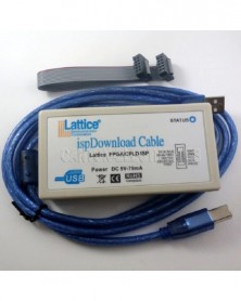
Rács isp letöltési kábel USB Jtag ISP FPGA CPLD programozó Diamond ispLever Win7 WIN8 WIN8.1 Linuxhoz
2 059 Ft 4 203 FtProduct Name: HW-USBN-2A Lattice ispDownload Cable USB Jtag ISP FPGA CPLD Programmer for Diamond ispLever Win7 WIN8 WIN8.1 Linux
You may need to:
Packing list:
1 x USB Download
1x USB 2.0 cable
1x 10PIN 2.54MM cable
Programmer Model : HW-USBN-2A
Support all LATTICE FPGA/CPLD devices:
MachXO( Bridging & IO Expansion FPGAs) :
MachXO3
MachXO2
MachXO
LatticeXP2
ispMach 4000ZE
ispMach 4000 V/B/C/Z
ECP( Connectivity & Acceleration FPGAs)
ECP5
LatticeECP3
LatticeECP2/M
LatticeSC/M
No separate installation drive , direct support Diamond/ispLever6.x/7.x/classic version , ispVM various versions (Development software can be downloaded at the official website of lattice)
USB standard B -type interface, using a standard USB cable to connect PC
USB powered, no external power supply
Support LSC ISPVM, LATTICE DEMIOND, LATTICE ISPEVER, and LATTICE PROGRAMMER
Support WIN 2K, WIN XP, WIN7 32, WIN7 64 WIN8 WIN8.1 Linux
Support for JTAG, internal FLASH, SPI FLASH programming mode , etc
-
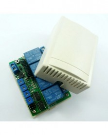
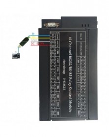
Szín: DC 12V - DC 12V 24V 8ch optikailag leválasztott IN USB COM relé modul UART RS232 soros port kapcsolótábla digitális
1 741 Ft 3 553 Ft
Product Name: DC 12V 24V 8ch Optically Isolated IN USB COM Relay Module UART RS232 Serial Port Switch Board Digital collector PLC
Package inlcuded:
1pcs USB
Serial Port Bpard
8CH Relay OUT & 8CH Optically isolated IN
Description:
1: Working voltage: DC 12V/24V optional
2: (DC12V)Standby current (all relays closed) 11MA, 1 relay open 39MA, 2 relays open 67MA, 3 relays open 94MA,4 relays open 120MA,5 relays open 146MA,6 relays open 172MA, 7 relays open 198MA,8 relays open 222MA
3 8 photoelectric isolation Input ports (NPN low level active ), the input and output relationship can be set to associated (default) and non-associated through commands.
4 UART serial port protocol, USB_B female interface (CH340 chip)
5 USB interface supports Windows(WIN10 WIN8 WIN7 WINXP), Linux and MAX operating systems
6: ''Open'' ''Close'' ''Momentary'' ''Self-locking'' ''Interlock'' ''Delay'' ''All Relays Open'' ''All Relays Close'' 8 Commands
7 Two kinds of commands: AT command and 8-byte command, the two commands are automatically recognized, no need to switch.
8: Under the ''Delay'' command ,the maximum delay is 9999 seconds(Only AT command)
9 Size: 111 * 63 * 19mm
10 Weight: 123 g
11 Maximum load: 10A / 250VAC, 10A / 125VAC, 10A / 30VDC, 10A / 28VDC, 10A / 12VDC
For more information, please contact me
Without the USB B cable, you need to purchase the USB cable separately.
Application
Remote control, remote measurement system;
Wireless meter
;
Smart Home,Home Automation ,Wiser Home;
Access control
;
Identification system
;
Digital quantity acquisition;
IT household appliance
;
Intelligence household appliance;
Baby monitoring system;
Typial application :
DC 1-110VAC 85-265V control circuit,Wiring diagram below(Note:If not DC5V/12V24V load, need another DC5V/12V24V power supply). ''LOAD'' may be LED lights, fans, motors Lights, fluorescent lights, solar water heaters and other DC AC equipment
-
Szín: DC 24V - DC 12V 24V 8ch optikailag leválasztott IN USB COM relé modul UART RS232 soros port kapcsolótábla digitális
1 758 Ft 3 587 Ft
Product Name: DC 12V 24V 8ch Optically Isolated IN USB COM Relay Module UART RS232 Serial Port Switch Board Digital collector PLC
Package inlcuded:
1pcs USB
Serial Port Bpard
8CH Relay OUT & 8CH Optically isolated IN
Description:
1: Working voltage: DC 12V/24V optional
2: (DC12V)Standby current (all relays closed) 11MA, 1 relay open 39MA, 2 relays open 67MA, 3 relays open 94MA,4 relays open 120MA,5 relays open 146MA,6 relays open 172MA, 7 relays open 198MA,8 relays open 222MA
3 8 photoelectric isolation Input ports (NPN low level active ), the input and output relationship can be set to associated (default) and non-associated through commands.
4 UART serial port protocol, USB_B female interface (CH340 chip)
5 USB interface supports Windows(WIN10 WIN8 WIN7 WINXP), Linux and MAX operating systems
6: ''Open'' ''Close'' ''Momentary'' ''Self-locking'' ''Interlock'' ''Delay'' ''All Relays Open'' ''All Relays Close'' 8 Commands
7 Two kinds of commands: AT command and 8-byte command, the two commands are automatically recognized, no need to switch.
8: Under the ''Delay'' command ,the maximum delay is 9999 seconds(Only AT command)
9 Size: 111 * 63 * 19mm
10 Weight: 123 g
11 Maximum load: 10A / 250VAC, 10A / 125VAC, 10A / 30VDC, 10A / 28VDC, 10A / 12VDC
For more information, please contact me
Without the USB B cable, you need to purchase the USB cable separately.
Application
Remote control, remote measurement system;
Wireless meter
;
Smart Home,Home Automation ,Wiser Home;
Access control
;
Identification system
;
Digital quantity acquisition;
IT household appliance
;
Intelligence household appliance;
Baby monitoring system;
Typial application :
DC 1-110VAC 85-265V control circuit,Wiring diagram below(Note:If not DC5V/12V24V load, need another DC5V/12V24V power supply). ''LOAD'' may be LED lights, fans, motors Lights, fluorescent lights, solar water heaters and other DC AC equipment
-
Szín: 50 cm-es USB B kábel - DC 12V 24V 8ch optikailag leválasztott IN USB COM relé modul UART RS232 soros port
156 Ft 319 Ft
Product Name: DC 12V 24V 8ch Optically Isolated IN USB COM Relay Module UART RS232 Serial Port Switch Board Digital collector PLC
Package inlcuded:
1pcs USB
Serial Port Bpard
8CH Relay OUT & 8CH Optically isolated IN
Description:
1: Working voltage: DC 12V/24V optional
2: (DC12V)Standby current (all relays closed) 11MA, 1 relay open 39MA, 2 relays open 67MA, 3 relays open 94MA,4 relays open 120MA,5 relays open 146MA,6 relays open 172MA, 7 relays open 198MA,8 relays open 222MA
3 8 photoelectric isolation Input ports (NPN low level active ), the input and output relationship can be set to associated (default) and non-associated through commands.
4 UART serial port protocol, USB_B female interface (CH340 chip)
5 USB interface supports Windows(WIN10 WIN8 WIN7 WINXP), Linux and MAX operating systems
6: ''Open'' ''Close'' ''Momentary'' ''Self-locking'' ''Interlock'' ''Delay'' ''All Relays Open'' ''All Relays Close'' 8 Commands
7 Two kinds of commands: AT command and 8-byte command, the two commands are automatically recognized, no need to switch.
8: Under the ''Delay'' command ,the maximum delay is 9999 seconds(Only AT command)
9 Size: 111 * 63 * 19mm
10 Weight: 123 g
11 Maximum load: 10A / 250VAC, 10A / 125VAC, 10A / 30VDC, 10A / 28VDC, 10A / 12VDC
For more information, please contact me
Without the USB B cable, you need to purchase the USB cable separately.
Application
Remote control, remote measurement system;
Wireless meter
;
Smart Home,Home Automation ,Wiser Home;
Access control
;
Identification system
;
Digital quantity acquisition;
IT household appliance
;
Intelligence household appliance;
Baby monitoring system;
Typial application :
DC 1-110VAC 85-265V control circuit,Wiring diagram below(Note:If not DC5V/12V24V load, need another DC5V/12V24V power supply). ''LOAD'' may be LED lights, fans, motors Lights, fluorescent lights, solar water heaters and other DC AC equipment
-
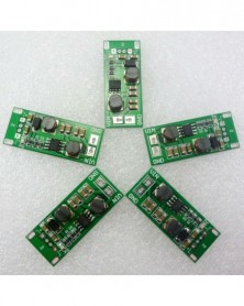
5 db 1-6,5 V-tól 5 V-ig terjedő, automatikus lépésenkénti lelépéses DC DC átalakító LED Motor 18650 napelemes
1 353 Ft 2 761 Ft
Product Name: 5pcs 1-6.5V to 5V auto step up step down DC DC converter for LED Motor 18650 solar panel charger
Packing list
5 pcs USB Auto buck-boost Voltage regulator (input DC 1-6V , output DC 5V -6% ) ;
Description:
Input voltage DC 1 ~ 6V, output DC 5V( -6% )
The maximum input voltage can not exceed 6.5V
Short-term maximum output current : 12000mA
Long time maximum output current: 1000mA
Auto Buck-Boost Converter Module working frequency 1MHZ.efficiency 60% -85% .
Operating temperature range : -25~ 85 Degrees Celsius
Storage temperature range : -45~ 125 Degrees Celsius
Size : 47mm x 16mm x 13.7mm
Weight : 6.4g
Applications:
Battery powered equipment
Wireless Module,NRF24L01 CC1101 CC2500 etc.
MCU Development Board,AVR PIC FPGA/CPLD STM32
Arduiuo uno mega2560 due Breadboard Raspberry Pi
LED Lighting
Wireless communication equipment
Audio equipment
Digital cameras,GPS,wireless transceiver
Portable devices
18650 solar panel charger
Attention :
This is a DC-DC voltage converter module,Must be noted when using:
1 Input voltage can not be greater than the maximum input range
2 Output power can not be greater than the maximum load for a long time
3 Input power must be greater than the output power, because the power consumption of the module itself
Q & A:
Q : Why output voltage is less than the nominal voltage
A : Input power supply power is too low.Test the input voltage with a multimeter,a t this time of the input voltage is very low -
5 DB 5W DC 5V–DC 12V Engedélyezze az IO-vezérlő kapcsolót, fokozatos átalakító tápegység
1 144 Ft 2 334 FtModule No.: TB322
Packing list:
5 PCS 3-6V to 12V with ON/OFF Switch Boost Modules
Description:
Input voltage 2.8 -6V, output 12V (deviation -5% )
Maximum input current: 1.5A
Long-term work Current: 1A
Conversion efficiency : 90%
PCB size : 25MM x 15MM
Start Voltage 2.8V, Output Current 50MA
INPUT 3V 1A; OUTPUT 12V 220MA
INPUT 3.3V 1A; OUTPUT 12V 250MA
INPUT 3.7V 1A; OUTPUT 12V 280MA
INPUT 4.5V 1A; OUTPUT 12V 340MA
INPUT 5V 1A; OUTPUT 12V 370MA
INPUT 6V 1A; OUTPUT 12V 450MA
This is with on/off switch voltage boost module.The master chip is FP6291GLR,for more Details,
Can used the input voltage (VIN or GND)control the switches,also use MCU IO control the switches.
Control current is very small, MCU IO port can be directly controlled. Including micro-controller : ARDIUNO UNO MEGA2560 AVR STM32 ARM PIC AT89C51 STC MSP430 FPGA CPLD etc.
When the EN pin = GND(OR MCU LOW level),the boost module is working properly;
When the EN pin = VIN(or MCU HIGH level,3.3V/5V) OR Not Connected(or MCU High impedance),
the boost module into standby mode, stops working, the output voltage is 0V(Can measure the output voltage is 500~800MV, which is inductive output voltage,you does not have to bother).
Applications
Battery powered equipment
Wirels mouse, Wireless keyboard
Toys
Camera, Video camera
VCR
PDA
LED Lighting
Wireless communication equipment
MP3/MP4 player
Audio equipment -
12V 433MHz RF késleltetési idő vezeték nélküli 1 db 4 gombos távirányító 4 db vevő
2 017 Ft 4 117 FtTypical applications:
DC 12V Home lighting system
Remote control switch
Smart Home / Home Automation
Garage Door
Fluorescent lamp Illumination
Motorcycle Electromobile
Remote controlled gates
Security Monitoring
LED lighting
Fluorescent lamp
DC 12 DC Motor,RS360
Wiring Diagram 1:
DC 12V control circuit,Wiring diagram below. "LOAD" may be LED lamp, fans, motors and other DC 12V Electrical equipment
Wiring Diagram 2:
DC 1-48V OR AC 85-265V control circuit,Wiring diagram below(Note:If not DC 12V load, need another DC 12V power supply). "LOAD" may be LED lamp, fans, motors and other DC AC equipment
Packing list:
4 PCS 433M DC 12V one Channel Delay Relay
1 PCS 433M Large Power 4 Button PT2262 Remote Control(USE 12V 23A battery,Batteries not included)
receiver Features:
1 Operating voltage: DC 12V;
2 Operating Current: relays close, about 9MA; relay open,about 42MA;
3 Operating frequency: 433.92M; 315M version can be customized
4 Receiver sensitivity : -108dBm
5 Decode : learning code, can be adapted EV1527 / PT2262 and compatible remote control, you can store up to 32 remote control
6 Work mode : Non-locking (Momentary is defult),Self-locking (Toggle),Inter-locking (Latch),Delay; 1-5000 seconds adjustable delay time, minimum step 0.1 seconds
7 Size(Including housing)50*35*22mm
8 Weight(including housing) 30g
9 Relay Maximum load(Recommended<5A):10A/250VAC,10A/125VAC,10A/30VDC, 10A/28VDC,10A/12VDC
Work mode
NO : Relay normally open contact
COM : Relay common contact
NC : Relay normally closed contact
Open : NO connection COM, NC disconnect COM
Close : NO disconnect COM, NC connection COM
Momentary : Press the Transmitter button , the receiver relay is Open, release button;the relay is Close;
Toggle : Press transmitter button for 1 time , the receiver relay is Open, press button again, the relay is Close;
Latched : Press transmitter button A, the receiver relay is Open Press transmitter button B, the receiver relay is Close.
Delay : Press the Transmitter button, the receiver relay Open,After a set time delay, the receiver relay is Close;
If during the delay, press the button of Transmitter, delay start again; if the delay period, press and hold the button of Transmitter 3-4 seconds, the receiver controller stops the delay, the relay Close
Adapter remote control (learning remote control):
Under normal operating mode, LED will be lit, when receives a valid remote control (EV1527 / PT2262) button values, LED flashes
Clean code: press the key and held down, LED off, LED will light about 8 seconds later, clean code is completed (Note: After performing clean code previously stored remote control value does not exist)
Step 1 (into the learning mode): Press the key (about 1 second), LED off;
Step 2 (adapter button): Then press the utton on the remote control, LED flashes four times on, then learning the button value
Note:
Only the Non-locking (Momentary is defult),Self-locking (Toggle),Inter-locking (Latch) mode to a "clear code" and " learning " action
In the "delay" mode can only set the delay time
Delay setting:
Step 1, the mode is set to "delay" mode (jumper cap on the M1 into two rows of pins)
Step 2, press the key until the LED is off
Step 3. Click the key again, LED flashes
Step 4. Click the key again after a period of time, LED light
LED blinking time is the delay time.
Transmitter :
Qty : 1 pcs 4Button Fixed code remote ;
Features / Specifications :
1. 4 buttons;
2. High stability, SMT chip, frequency stabilization SAW, ultra-high-frequency transistor;
3: Large power;
Technical Data :
Transmitter Module No.: TB420;
Power supply : 12V 23A battery (not included ) , please buy battery from here :
Operating current: 28-33mA;
Oscillation mode: SAW resonator;
Modulation mode:ASK/OOK;
Operating frequency:433.92MHZ ;
Encoding format: SCT2260 fixed code (compatiable for PT2262 SC2262 PT2260 PT2264 , can work with PT2272-M4 ,PT2272-T4,PT2272-L4 );
RC Resistance : 4.7M;
Transmit power : 200mW ;
-
315 MHz-es ASK Super Heterodyne EV1527 PT2262 PT2272 RF távoli vezeték nélküli kapcsolati készletek
1 086 Ft 2 217 FtTypical applications:
Remote control switch
Smart Home / Home Automation
Diy UNO MEGA2560 Remote Control
RC switch
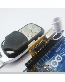
Product Name : UNO Wireless Decoding Kit 4CH RF Remote Control Switch EV1527 Keyfob for Arduiuo Mega2560 DUE
Package inlcuded (Does not include Arduiuo UNO)
1 pcs 433M 1527/2262 Superheterodyne Receiver decoder module;
1 pcs 433M EV1527 transmitter remote (This remote doesnot have a battery(12V 27A) , Please buy in your local market ) .
Arduiuo uno/mega2560 Code :
//*******************************************//
//Author: cantone-electonics
//More information welcome to : www.canton-electronics.com
//Arduiuo 1.0.4
//uno R3
//uno 4 channel EV1527/PT2262 Decoding module
int VCC = 13;//as power vcc
int D3 = 12;
int D2 = 11;
int D1 = 10;
int D0 = 9;
int VT = 8;
int Relay1 = A0;
int Relay2 = A1;
int Relay3 = A2;
int Relay4 = A3;
int InputState = 1; //variable for reading the input status
// the setup routine runs once when you press reset:
void setup() {
// initialize the digital pin
pinMode(VCC, OUTPUT);
pinMode(D3, INPUT);
pinMode(D2, INPUT);
pinMode(D1, INPUT);
pinMode(D0, INPUT);
pinMode(VT, INPUT);
digitalWrite(VCC, HIGH);//AS VCC
/*
//Activate input pin internal pull-up resistors
digitalWrite(I0, HIGH);
digitalWrite(I1, HIGH);
digitalWrite(I2, HIGH);
digitalWrite(I3, HIGH);
digitalWrite(VT, HIGH);
*/
Serial.begin(9600);
delay(2000);//Waiting for rf receiver module startup
}
// the loop routine runs over and over again forever:
void loop() {
InputState = digitalRead(VT);
if(InputState)
{
Serial.print("D3 D2 D1 D0 VT \n");
InputState = digitalRead(D3);
if(InputState) Serial.print("1 ");else Serial.print("0 ");
InputState = digitalRead(D2);
if(InputState) Serial.print("1 ");else Serial.print("0 ");
InputState = digitalRead(D1);
if(InputState) Serial.print("1 ");else Serial.print("0 ");
InputState = digitalRead(D0);
if(InputState) Serial.print("1 ");else Serial.print("0 ");
Serial.print("1\n");
}
do{
InputState = digitalRead(VT);
}while(InputState);
}
//*******************************************//
Description:
433M 1527/2262 Superheterodyne Receiver decoder module, click here;
433M EV1527 transmitter remote, click here.
transmitter remote Power supply : 12V 27A battery . (This remote doesnot have a battery , Please buy in your local market )
Can directly insert Arduiuo UNO/MEGA2560/DUE(also can use other MCU:ARM FPGA/CPLD PIC AVR Etc. )
Connect with ardiuno :
-
AMS117-3.3V DC 4.5-7V 5V-3.3V Buck Setp-dowm LDO modul és IIC I2C UART logikai szint átalakító NRF24L01 CC1101CC2500 SI4432
1 189 Ft 2 427 FtProduct Name : AMS117-3.3V DC 4.5-7V 5V to 3.3V Buck Setp-dowm LDO Module & IIC I2C UART Logic Level Converter for NRF24L01 CC1101CC2500 SI4432
Packing list:
24 pcs 2 in 1 5V to 3.3V DC-DC Setp-dowmLDO Module & Base 470ohm Resistor Logic Level Converter;
Description:
1 On board DC 4.5V-7V to 3.3V DC-DC Step-Down Power Supply LDO voltage Regulator Module,base AMS1117-3.3;
2 On board 8 channels 5V to 3.3V(also 3.3V to 5V) TTL Logic level converter,base Limiting resistor;
3 2.54MM Pin,UNO MEGA2560 DUE Breadboard friendly;
4 PCB size:25* 15mm
Application for:
Arduiuo UNO MEGA2560 DUE Pro mini Nano
NRF24L01
CC11O1
NRF24LE1
CC2500
ZIGBEE/CC2530
Bluetooth
raspberry pi banana pi
FPGA/CPLD ARM AVR PIC C8051 MSP430 STM32
MCU Development Board
TTL Level conversion principle:
Between 5V and 3.3V level plus 470ohm current limiting resistor, to avoid being burned of 3.3V port.
So, when the LOW side no-load, HIGH side plus 5V level,LOW side test is still at 5V level,vice versa.
This is a normal phenomenon, not the level conversion function does not work.
Schematics:
-
Késleltetett távirányító relé Smart Home Kit 433M Multifunkciós BE/KI kapcsoló időzítéssel Nem reteszelő Önzáró
1 121 Ft 2 287 Ft
Typical applications:
DC 12V Home lighting system
Remote control switch
Smart Home / Home Automation
Garage Door
Fluorescent lamp Illumination
Motorcycle Electromobile
Remote controlled gates
Security Monitoring
LED lighting
Fluorescent lamp
DC 12 DC Motor,RS360
Wiring Diagram 1:
DC 12V control circuit,Wiring diagram below. "LOAD" may be LED lamp, fans, motors and other DC 12V Electrical equipment
Wiring Diagram 2:
DC 1-48V OR AC 85-265V control circuit,Wiring diagram below(Note:If not DC 12V load, need another DC 12V power supply). "LOAD" may be LED lamp, fans, motors and other DC AC equipment
Product Name : Delay remote control relay Smart Home Kit 433M Multifunction ON/OFF Switch with Timing Non-locking Self-locking Inter-locking
Packing list:
1 PCS 433M DC 12V one Channel Delay Switch
1 PCS 433M Large Power 2 Button EV1527 Remote Control (USE 12V 27A battery,Batteries not included)
receiver Features:
1 Operating voltage: DC 12V;DC 5V version can be customized
2 Operating Current: relays close, about 9MA; relay open,about 42MA;
3 Operating frequency: 433.92M; 315M version can be customized
4 Receiver sensitivity : -108dBm
5 Decode : learning code, can be adapted EV1527 / PT2262 and compatible remote control, you can store up to 32 remote control
6 Work mode : Non-locking (Momentary is defult),Self-locking (Toggle),Inter-locking (Latch),Delay; 1-5000 seconds adjustable delay time, minimum step 0.1 seconds
7 Size(Including housing)50*35*22mm
8 Weight(including housing) 30g
9 Relay Maximum load(Recommended<5A):10A/250VAC,10A/125VAC,10A/30VDC, 10A/28VDC,10A/12VDC
Work mode
NO : Relay normally open contact
COM : Relay common contact
NC : Relay normally closed contact
Open : NO connection COM, NC disconnect COM
Close : NO disconnect COM, NC connection COM
Momentary : Press the Transmitter button , the receiver relay is Open, release button;the relay is Close;
Toggle : Press transmitter button for 1 time , the receiver relay is Open, press button again, the relay is Close;
Latched : Press transmitter button A, the receiver relay is Open Press transmitter button B, the receiver relay is Close.
Delay : Press the Transmitter button, the receiver relay Open,After a set time delay, the receiver relay is Close;
If during the delay, press the button of Transmitter, delay start again; if the delay period, press and hold the button of Transmitter 3-4 seconds, the receiver controller stops the delay, the relay Close
Adapter remote control (learning remote control):
Under normal operating mode, LED will be lit, when receives a valid remote control (EV1527 / PT2262) button values, LED flashes
Clean code: press the key and held down, LED off, LED will light about 8 seconds later, clean code is completed (Note: After performing clean code previously stored remote control value does not exist)
Step 1 (into the learning mode): Press the key (about 1 second), LED off;
Step 2 (adapter button): Then press the utton on the remote control, LED flashes four times on, then learning the button value
Note:
Only the Non-locking (Momentary is defult),Self-locking (Toggle),Inter-locking (Latch) mode to a "clear code" and " learning " action
In the "delay" mode can only set the delay time
Delay setting:
Step 1, the mode is set to "delay" mode (jumper cap on the M1 into two rows of pins)
Step 2, press the key until the LED is off
Step 3. Click the key again, LED flashes
Step 4. Click the key again after a period of time, LED light
LED blinking time is the delay time.
Power supply : 12V 27A battery replacable . (This remote doesnot have a battery , Please buy in your local market )
Operating current: ≤ 12mA ;
Oscillation mode: SAW resonator ;
Oscillation resistor : 330K
Modulation mode: ASK OOK ;
Operating frequency: 433.92MHz ;
Frequency dev iation: ±0.2MHz ;
Encoding format: Million Group Code ( EV1527 ) ;
Transmit power: 10 mW.
Data Rate : 50~60KHZ;
-
433M RF 1-5000 másodperc, állítható lépés, 0,1 s többfunkciós késleltető relé Smart Home kapcsoló Vezeték nélküli
1 105 Ft 2 256 Ft
Typical applications:
DC 12V Home lighting system
Remote control switch
Smart Home / Home Automation
Garage Door
Fluorescent lamp Illumination
Motorcycle Electromobile
Remote controlled gates
Security Monitoring
LED lighting
Fluorescent lamp
DC 12 DC Motor,RS360
Wiring Diagram 1:
DC 12V control circuit,Wiring diagram below. "LOAD" may be LED lamp, fans, motors and other DC 12V Electrical equipment
Wiring Diagram 2:
DC 1-48V OR AC 85-265V control circuit,Wiring diagram below(Note:If not DC 12V load, need another DC 12V power supply). "LOAD" may be LED lamp, fans, motors and other DC AC equipment
Product Name : 433M RF 1-5000 seconds Adjustable Step 0.1s Multifunction Delay Relay Smart Home Switch Wireless transmit receive module
Packing list:
1 PCS 433M DC 12V one Channel Delay Switch
2 PCS 433M Large Power 2 Button EV1527 Remote Control (USE 12V 27A battery,Batteries not included)
receiver Features:
1 Operating voltage: DC 12V;DC 5V version can be customized
2 Operating Current: relays close, about 9MA; relay open,about 42MA;
3 Operating frequency: 433.92M; 315M version can be customized
4 Receiver sensitivity : -108dBm
5 Decode : learning code, can be adapted EV1527 / PT2262 and compatible remote control, you can store up to 32 remote control
6 Work mode : Non-locking (Momentary is defult),Self-locking (Toggle),Inter-locking (Latch),Delay; 1-5000 seconds adjustable delay time, minimum step 0.1 seconds
7 Size(Including housing)50*35*22mm
8 Weight(including housing) 30g
9 Relay Maximum load(Recommended<5A):10A/250VAC,10A/125VAC,10A/30VDC, 10A/28VDC,10A/12VDC
Work mode
NO : Relay normally open contact
COM : Relay common contact
NC : Relay normally closed contact
Open : NO connection COM, NC disconnect COM
Close : NO disconnect COM, NC connection COM
Momentary : Press the Transmitter button , the receiver relay is Open, release button;the relay is Close;
Toggle : Press transmitter button for 1 time , the receiver relay is Open, press button again, the relay is Close;
Latched : Press transmitter button A, the receiver relay is Open Press transmitter button B, the receiver relay is Close.
Delay : Press the Transmitter button, the receiver relay Open,After a set time delay, the receiver relay is Close;
If during the delay, press the button of Transmitter, delay start again; if the delay period, press and hold the button of Transmitter 3-4 seconds, the receiver controller stops the delay, the relay Close
Adapter remote control (learning remote control):
Under normal operating mode, LED will be lit, when receives a valid remote control (EV1527 / PT2262) button values, LED flashes
Clean code: press the key and held down, LED off, LED will light about 8 seconds later, clean code is completed (Note: After performing clean code previously stored remote control value does not exist)
Step 1 (into the learning mode): Press the key (about 1 second), LED off;
Step 2 (adapter button): Then press the utton on the remote control, LED flashes four times on, then learning the button value
Note:
Only the Non-locking (Momentary is defult),Self-locking (Toggle),Inter-locking (Latch) mode to a "clear code" and " learning " action
In the "delay" mode can only set the delay time
Delay setting:
Step 1, the mode is set to "delay" mode (jumper cap on the M1 into two rows of pins)
Step 2, press the key until the LED is off
Step 3. Click the key again, LED flashes
Step 4. Click the key again after a period of time, LED light
LED blinking time is the delay time.
Power supply : 12V 27A battery replacable . (This remote doesnot have a battery , Please buy in your local market )
Operating current: ≤ 12mA ;
Oscillation mode: SAW resonator ;
Oscillation resistor : 330K
Modulation mode: ASK OOK ;
Operating frequency: 433.92MHz ;
Frequency dev iation: ±0.2MHz ;
Encoding format: Million Group Code ( EV1527 ) ;
Transmit power: 10 mW.
Data Rate : 50~60KHZ;
-
DC 5V 7.5V 9V 2Ch RS232 relékártya távirányító USB PC UART COM soros portok
991 Ft 2 023 FtTypial application :
1 DC 5V control circuit,Wiring diagram below. ''LOAD'' may be LED lights, fans, motors and other AC DC equipment
2 DC 7-12V(7.5V 9V) control circuit,Wiring diagram below ''LOAD'' may be LED lights, fans, motors and other DC AC equipment
Package inlcuded: 1 x DC 5V-12V 2Ch RS232 Relay Board:
Description:
2 Channel Relay Module;
Power input: DC 5V/ 7-12V(Recommed 7.5V 9V)
PC Serial ports RS232 Control Relay;
Power indicator: LED lights ;
Output indication: relay output with LED indicators, easy to see working status of the relay ;
Communication protocol: UART protocol communication, baud rate 9600kpbs, 8 data bits, one stop bit, no parity. Each data frame contains eight bytes. Two-way data transmission.
Baud rate 9600kbps, 8 data bits, one stop bit, no parity. Each data frame contains eight bytes..
Size : 71x47mm x 19
Weight : 45g
1 Control commands:
1. Reading status(reading the satus of the relay (on/off))
Channel 1 :55 56 00 00 00 01 00 AC
Channel 2 :55 56 00 00 00 02 00 AD
Channel 3 :55 56 00 00 00 03 00 AE
Channel 4 :55 56 00 00 00 04 00 AF
2. Relay open (issue this command ,Relay open , COM connect to NO )
Channel 1 :55 56 00 00 00 01 01 AD
Channel 2 :55 56 00 00 00 02 01 AE
Channel 3 :55 56 00 00 00 03 01 AF
Channel 4 :55 56 00 00 00 04 01 B0
3. Relay close (issue this command ,Relay close , COM disconnect NO , and COM connect to NC )
Channel 1 :55 56 00 00 00 01 02 AE
Channel 2 :55 56 00 00 00 02 02 AF
Channel 3 :55 56 00 00 00 03 02 B0
Channel 4 :55 56 00 00 00 04 02 B1
4. Relay toggle(Relay status reversal,if COM connect to NO,this commands will Disconnect COM to NO and Reverse COM connect to NC,and vice versa)
Channel 1 :55 56 00 00 00 01 03 AF
Channel 2 :55 56 00 00 00 02 03 B0
Channel 3 :55 56 00 00 00 03 03 B1
Channel 4 :55 56 00 00 00 04 03 B2
5. Relay momentary(Relay COM connect to NO,disconnect after 200MS )
Channel 1 :55 56 00 00 00 01 04 B0
Channel 2 :55 56 00 00 00 02 04 B1
Channel 3 :55 56 00 00 00 03 04 B2
Channel 4 :55 56 00 00 00 04 04 B3
6.Relay Interlock
Channel 1 :55 56 00 00 00 01 05 B1
Channel 2 :55 56 00 00 00 02 05 B2
Channel 3 :55 56 00 00 00 03 05 B3
Channel 4 :55 56 00 00 00 04 05 B4
Once issue a command, will have a return fame , 7th byte of return fame mean the satus of realy .
2 return command
1.Return relay open(return this command,mean COM connect to NO )
Channel 1 :33 3C 00 00 00 01 01 71
Channel 2 :33 3C 00 00 00 02 01 72
Channel 3 :33 3C 00 00 00 03 01 73
Channel 4 :33 3C 00 00 00 04 01 74
2.Return relay close(return this command,mean COM disconnect NO , and COM connect to NC )
Channel 1 :33 3C 00 00 00 01 02 72
Channel 2 :33 3C 00 00 00 02 02 73
Channel 3 :33 3C 00 00 00 03 02 74
Channel 4 :33 3C 00 00 00 04 02 75
Instruction manual Please ask us after the purchase
Application
Remote control, remote measurement system;
Wireless meter;
Smart Home,Home Automation ,Wiser Home;
Access control ;
Identification system;
Data collection;
IT household appliance;
Intelligence household appliance;
Baby monitoring system;
-
DC 12V 433M LED Vezeték nélküli távirányító kapcsoló Relé modul a fény világító motorjához
1 037 Ft 2 117 Ft
Typical applications:
DC 12V LED Light
Remote control switch
Smart Home / Home Automation
Fluorescent lamp
DC 12 DC Motor,RS360
Wiring Diagram 1:
Wiring Diagram 2:
Product Name : DC 12V 433M LED Wireless remote control switch Relay Module for light Illumination Motor
Packing list:
1 PCS DC 12V 433M RF Wireless Receiver Learning code Relay
1 PCS 433M PT2262 1 Channel Remote Control (use 2 pcs CR2016 Battery , this remote doesnot have a battery)
Technical indicators:
operating voltage : DC 12V;
Operating frequency : 433.92MHz ;
Receiver sensitivity :-95dB;
Encoding: Receiver Recording;
Momentary / Latch / Toggle selectable (defult is Momentary , Latch Mode need 2 buttons handsender );
Learning function (can works with EV1527 and PT2262 remote, can store 16 pcs different code remote );
PCB Size:41×20×15mm;
Max load : 500W;
Advantage :
1: Receiver Mother board have a learning key , if the remote is lost , must buy EV1527 OR Pt2262 remotes to re-learn;
For more information,click here
433M PT2262 Remote Control:
Technical Data :
Power supply : DC6V , 2 pcs CR2016 replacable .(This remote doesnot have a battery , Please buy in your local market );
Operating current: ≤ 18mA;
Oscillation mode: SAW resonator;
Modulation mode: ASK/OOK;
Operating frequency: 433.92MHZ ;
Encoding IC : PT2262 OR compatiable IC;
Output power : 9dBm (8mW) ;
Data Rate : <10Kbps ;
RC Resistance : 4.7M ;
-
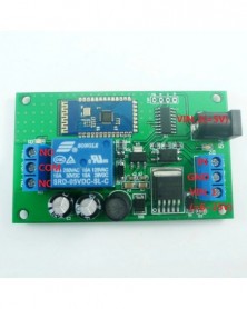
DC 5V 6V 9V 12V 15V 24V Bluetooth-kompatibilis relémodul Android APP Mobiltelefon Távirányító
1 068 Ft 2 180 Ft
Typical applications:
Home lighting system
Remote control switch
Remote locking
Smart Home / Home Automation
DC 12V LED lighting
Fluorescent lamp
12V DC Motor
Fluorescent lamp
Automotive electronics
Industrial automation and control
1 Power supply is DC 6-25V, ''LOAD'' also DC 6-25V circuit, wiring diagram below.
''LOAD'' may be LED lights, fans, motors and other DC 6-25V equipment
2 Power supply is DC 6-25V, ''LOAD'' is DC 1-48V or AC 85-265V circuit, wiring diagram below.
''LOAD'' may be LED lights, fans, motors and other DC 1-48V or AC 85-265V equipment
3 Power supply is DC5V, ''LOAD'' is DC 1-48V or AC 85-265V circuit, wiring diagram Below.
''LOAD'' may be LED lights, fans, motors and other DC 1-48V or AC 85-265V equipment
4 Power supply is DC 5V, ''LOAD'' is DC 5V circuit, wiring diagram below.
''LOAD'' may be LED lights, fans, mcu Development Boards and other DC 5V equipment
Product Name:DC 5V 6V 9V 12V 15V 24V Bluetooth Relay Module Android APP Mobile Phone Remote control
Package inlcuded:
1 PCS DC 5V-25V 1 Ch Android Bluetooth Relay Module
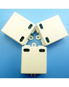
If you need housing, click here,White,Black.
Description:
1 Operating voltage: power supply 1, DC 6-25V; power supply 2,DC 5V
2 Operating Current: Standby 11MA, Relay Open 45MA (voltage DC 12V)
3 Bluetooth V2.1 EDR, Class 2
4 2.4GHz-2.48GHz unlicensed ISM band
5 send commands via Android Bluetooth APP control relay turned on and off (we provide Bluetooth APP, you can also use your own APP to control relays, sending commands to control),It can also be triggered by an external pulse signal.
6 ''Momentary'' ''Self-locking'' ''open'' ''close'' 4 Commands
7 External trigger input, opto-isolated switch, low pulse inputs.
8 size 79 * 47.5 * 20
9 Weight : 34g
10 Relay Maximum load:10A/250VAC ,10A/125VAC,10A /30VDC, 10A /28VDC ,10A /12VDC
Bluetooth relay manual:
NO : Relay normally open contact
COM : Relay common contact
NC : Relay normally closed contact
Momentary : Mobile terminal input ''A0'', the relay is ''open'',and after delay of 1 second the relay is ''Close''.
Self-locking : Mobile terminal input ''A1'', the relay is ''Open'', input ''A1'', the relay is ''Close'', and so on
Open : NO connection COM, NC disconnect COM
Close : NO disconnect COM, NC connection COM
External trigger input: low pulse triggering, pulse width greater than 200 milliseconds.
Two control methods, external trigger signal and Command Control,It can be composed of flexible and diverse control.
CommandS (Format: character, case-insensitive)
CommandS
Features
Description
A0
''Momentary''
Mobile terminal input ''A0'', the relay is ''open'',and after delay of 1 second the relay is ''Close''.
A1
'' Self-locking ''
Mobile terminal input ''A1'', the relay is ''Open'', input ''A1'', the relay is ''Close'', and so on
A2
'' Open ''
NO connection COM, NC disconnect COM
A3
'' Close ''
NO disconnect COM, NC connection COM
A4
'' Open ''
NO connection COM, NC disconnect COM
Bluetooth APP operations:
Access Password : 1234
Bluetooth Baud rate: 9600BPS
For more information, please contact me -
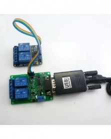
9V 12V 4Ch soros port UART RS232 relé távirányító készlet
1 343 Ft 2 740 Ft
Product Name: 9V 12V 4 Channel Serial port Relay Remote Control " 2Ch UART Relay Board 2 Channel Relay Module usb to RS232 Converter "
Package inlcuded:
1 x DC 9V 12V 2 Channel RS232 Relay Board
1 x DC 5V 2 Channel Expansion Relay Board
1 x USB to RS232 (PL2303 IC)
4 x DuPont wire(Random Color)
Description:
4 Channel Relay Board : 2 Channel RS232 Relay Board 2 Channel Expansion Relay Board;
2 Channel RS232 Relay Board 2 Power input: Power supply 1 DC 5V; Power supply 2 DC 9-12V.
2 Channel Expansion Relay Board : Power supply DC 5V
PC Serial ports RS232 Control Relay;
Power indicator : LED lights;
Output indication : relay output with LED indicators,easy to see working status of the relay;
Communication protocol: UART protocol communication, baud rate 9600kpbs, 8 data bits, one stop bit, no parity. Each data frame contains eight bytes. Two-way data transmission.
Baud rate 9600kbps, 8 data bits, one stop bit, no parity. Each data frame contains eight bytes.
PCB Size : RS232 Relay Board 71 x 47mm; Expansion Relay Board 52 x 38mm
1 Control commands:
1. Reading status(reading the satus of the relay (on/off))
0x55 0x56 0x00 0x00 0x00 0x00 0x00 0xAB
2. Relay open (issue this command ,Relay open,COM connect to NO)
Channel 1 : 0x55 0x56 0x00 0x00 0x00 0x01 0x01 0xAD
Channel 2 : 0x55 0x56 0x00 0x00 0x00 0x02 0x01 0xAE
Channel 3 : 0x55 0x56 0x00 0x00 0x00 0x03 0x01 0xAF
Channel 4 : 0x55 0x56 0x00 0x00 0x00 0x04 0x01 0xB0
3. Relay close (issue this command ,Relay close ,COM disconnect NO,and COM connect to NC)
Channel 1 : 0x55 0x56 0x00 0x00 0x00 0x01 0x02 0xAE
Channel 2 : 0x55 0x56 0x00 0x00 0x00 0x02 0x02 0xAF
Channel 3 : 0x55 0x56 0x00 0x00 0x00 0x03 0x02 0xB0
Channel 4 : 0x55 0x56 0x00 0x00 0x00 0x04 0x02 0xB1
4. Relay toggle(Relay status reversal,if COM connect to NO,this commands will Disconnect
COM to NO and Reverse COM connect to NC,and vice versa)
Channel 1 : 0x55 0x56 0x00 0x00 0x00 0x01 0x03 0xAF
Channel 2 : 0x55 0x56 0x00 0x00 0x00 0x02 0x03 0xB0
Channel 3 : 0x55 0x56 0x00 0x00 0x00 0x03 0x03 0xB1
Channel 4 : 0x55 0x56 0x00 0x00 0x00 0x04 0x03 0xB2
5. Relay momentary(Relay COM connect to NO,disconnect after 200MS)
Channel 1 : 0x55 0x56 0x00 0x00 0x00 0x01 0x04 0xB0
Channel 2 : 0x55 0x56 0x00 0x00 0x00 0x02 0x04 0xB1
Channel 3 : 0x55 0x56 0x00 0x00 0x00 0x03 0x04 0xB2
Channel 4 : 0x55 0x56 0x00 0x00 0x00 0x04 0x04 0xB3
Once issue a command,will have a return fame, 7th byte of return fame mean the satus of realy
2 return commands:
1.Return relay open(return this command,mean COM connect to NO)
Channel 1 : 0x33 0x3C 0x00 0x00 0x00 0x01 0x01 0x71
Channel 2 : 0x33 0x3C 0x00 0x00 0x00 0x02 0x01 0x72
Channel 3 : 0x33 0x3C 0x00 0x00 0x00 0x03 0x01 0x73
Channel 4 : 0x33 0x3C 0x00 0x00 0x00 0x04 0x01 0x74
2.Return relay close(return this command,mean COM disconnect NO,and COM connect to NC)
Channel 1 : 0x33 0x3C 0x00 0x00 0x00 0x01 0x02 0x72
Channel 2 : 0x33 0x3C 0x00 0x00 0x00 0x02 0x02 0x73
Channel 3 : 0x33 0x3C 0x00 0x00 0x00 0x03 0x02 0x74
Channel 4 : 0x33 0x3C 0x00 0x00 0x00 0x04 0x02 0x75
Instruction manual Please ask us after the purchase
Application
Remote control, remote measurement system;
Wireless meter ;
Smart Home,Home Automation ,Wiser Home;
Access control ;
Identification system ;
Data collection;
IT household appliance ;
Intelligence household appliance;
Baby monitoring system;
Home Appliances;
Reversible Motor Control;
Typial application :
1 DC 12V control circuit,Wiring diagram below. "LOAD" may be LED lights, fans, motors and other DC 12V equipment
2 DC 1-48V OR AC 85-265V control circuit,Wiring diagram below(Note:If not DC 12V load, need another DC 12V power supply). "LOAD" may be LED lights, fans, motors and other DC AC equipment
Test Software:(Only support win xp (32/62) win 7 (32/62) Operating System)
-
ALTERA ByteBlaster II USB Blaster CPLD FPGA JTAG letöltési kábel Win8 Linux EMP240 EPM570 EP4CE6 Cyclone IV fejlesztői
528 Ft 1 077 FtProduct Name:ALTERA ByteBlaster II USB Blaster CPLD FPGA JTAG Download Cable Win8 Linux for EMP240 EPM570 EP4CE6 Cyclone IV Development Board
Module No.: TB069
Packing list:
1 PCS Altera USB Blaster (with USB wire and 10 pin JTAG wire)
1. Support 1.5V,1.8V,2.5V,3.5V and 5.0V.
2. Support all ALTERA products : CPLD ( MAX3000, MAX7000, MAX9000 and MAX II ) ; FPGA ( Stratix, StratixII, Cyclone, CycloneII, ACEX 1K, APEX20K and FLEX 10K ) ;Active serial configuration device (EPCS1, EPCS4, EPCS16)
---- Now we have tested chip using this tool is: Cyclone (EP1C3, EP1C6, EP1C12, EP1C20) ; Cyclone II (EP2C5, EP2C8, EP2C35) ;Cyclone IV(EP4CE6 EP4CE10) Stratix (EP1S10, EP1S20, EP1S25) ; Stratix II(EP2S60) ; FLEX10K(EPF10K10, EPF0K30) ; ACEX1K(EP1K30) ; MAX7000(MAX7128SLC84, MAX7128) ; AETC100(MAX3000, MAX3128) ; MAXII(EPM240, EPM570, EPM1270) ; EPCS(EPCS1, EPCS4, EPCS16) ; EPC(EPC1, EPC4)
3. Support AS, PS and JTAG program ( with Verify and BankCheck function) .
---- When we tested the chip above , we use the different program mode: JTAG ( Cyclone, CycloneII, Stratix II, Flex10K, Acex1K, Max7000 and Max3000) ; AS ( EPCS1, EPCS4, EPCS16 ) ; PS ( Stratix , Stratix GX )
4. Support embedded logic analyzer function of SignalTapII
5. Support NIOS II communication and debugger -- When you use it to debug your Black Gold , it will not Pop-up warning
6. Faster -- about 6 times than ByteblasterII
7. USB interface ! -- you don't need a PC with serial port now
Operating System Support:
1, Windows XP, Windows Vista, Windows7 ,Windows 8 Windows 8.1 USB interface;
2, Quartus II version 4.0 or newer version;
3,Quartus II Software Download : www.altera.com
This programmer uses standard 10-Pin ICD10 interface, the Pin assignment is shown as followed:
-
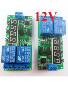
DC 5V 2 csatornás 9 funkció késleltetés időzítő relé modul vezérlő motor fordított ciklus hurok időzítők
579 Ft 1 182 Ft
Typical applications
1 Motor reversing control circuit,Power supply is DC 5V ,Wiring diagram below. ''LOAD'' may be DC 1-110V OR 85-265V AC/DC Motor
2 Live wire and Netural wire control circuit,Power supply is DC 5V ,Wiring diagram below. ''LOAD'' may be AC 85-265V equipment
Product Name: DC 5V 2 Channel Multifunction Delay Timer Module Delay Relay Controller Motor Reverse Cycle Loop Timers Interlock Switch Board
Package inlcuded:
1 PCS DC 5V 2 channel multi-function delay relay board
Description:
DC 5V 2 channels 0-9999 seconds multi-function delay relay board
Nine kinds of functions can be switched
Products can set the delay time and Function.After setting up, power-up setting value is previous setting delay time and Function as we set last time (power-down memory function);
Size: 75mm × 35mm x 20mm
Weight : 35g
Relay maximum load capacity: DC 1-110V/6A; AC 85-250V/5A
User Manua:
Noun resolved:
COM : Common terminal
NO: Normal open
NC: Normally Close
Relay close: COM connect NO,COM disconnect NC
Relay open : COM disconnect NO,COM connect NC
Function mode :
F1 After power on. Relay 1 close,relay 2 open, delay time is T1. Then relay 1 open,relay 2 is close. Delay time is T2.Relay 1 close, relay 2 open, delay time is T1.Such repeated cycles of action...(for Motor reversing)
F2 After power on.Relay 1 close, relay 2 close, delay time is T1. Then relay 1 open, relay 2 is open. Delay time is T2 . Relay 1 close , relay 2 close, delay time is T1. Such repeated cycles of action...
F3 After power on . Relay 1 close , delay time is T1. Then relay 1 open , Delay time is T2 . Relay 1 close,delay time is T1. Such repeated cycles of action... ,Relay 2 never work .
F4 After power on . Relay 2 open , delay time is T1. Then relay 2 close, Delay time is T2 . Relay 2 close , delay time is T1. Such repeated cycles of action... ,Relay 1 never work .
F5 After power on . Relay1 and relay 2 close, delay time is T1.Relay1 and relay 2 open (control Live wire and netural wire)
F6 After power on . Relay 1 close , delay time is T1. Then relay 1 open,Relay 2 never work .
F7 After power on . Relay 2 no action, delay time is T1. Then relay 2 close, Relay 1 never work .
F8 After power on. Relay 1 and Relay 2 both close, delay time is T1. Then relay 1 open,Delay time is T2, relay 2 open.
F9 After power on . Relay 1 and Relay 2 both open , delay time is T1. Then relay 1 close, Delay time is T2, relay 2 close.
Function Mode Switch:
Keep pressing K1, press K2 to switch Function mode
F5 F6 F7 mode has only 1 delay time counter (T1), the other mode has two delay time counters (T1 T2); Keep pressing K1 ,press K3, switch T1 T2 counter .
Adjustment delay time :
Press K2, switching 4 bits of delay time counter(0000~9999S),the selected bit flash , press K3 to adjusted counter . Repeat to switch the rest bits .
After switching all bits ,then press K2 exit adjustable delay mode; or press K1, exit adjustable delay mode; or wait 10 seconds exit adjustment mode
Display way :
Keep pressing the K3 for 5 seconds , the digital display Turn off. Keep pressing K3 5 second more (or re-power), the digital display Turn on .
F5 F6 F7 F8 F9 mode, the delay counter is completed, digital display Turn off, enter a low-power mode, press K1, exit the low-power mode
-
433MHz PT2262 PT2272 EV1527 kódoló Arduino dekóder RF adó-vevő vevő készlethez
1 282 Ft 2 616 FtBelow item is powered by Canton-electronics Ltd .
Kit No: RT382 433MHz
Receiver :
Demo :
Connect with ardiuno :
Model No.
TB417
Operating voltage
5.0VDC ±0.5V
Working priceple
Super Heterodyne receiver with decoder , learning type . decoding PT2262, PT2260, PT2240, EV1527 and other learning codeto chip or compatible chips, can learn and store 20 pcs different coded remote control. Intelligently distinguish shock resistance between fixed code and learning code , such as PT2262 and EV1527.
Static current
≤7 mA (DC 5V)
Operating frequency
433MHz
modulation Mode
ASK/OOK
Receiving sensitivity
over -110 dBm (50 Ω)
Speed
< 5 K bps (at 315 MHz, -95 dBm)
Operating temp.
-10 °C ~ 60 °C
Max rate 1 KHZ
Antenns length
20 cm (315 MHz), 18 cm (433.92 MHz)
Dimension
30*13mm
Output signal
TTL level , Momentary, Latch, Toggle ,user can set it by welding, Latch is defult.
Band width
2MHz(315MHz, Sensitivity go down 3dBm test )
Output
A.Momentary ----all disconnect (defult) ;
B. Toggle ---- connect T ;
C.Latch ---- connect L ;
1: This is a simple wireless remote control module, no additional instructions.
2 : VT output high (5V TTL level) when signal received;
3: D1 D2 D3 D4 four data pins corresponding to four buttons on the remote control, for example: when the A button on the remote control is pressed, D1 high output, etc.
4: VT and D1-4 pins are 5V TTL pin 10MA maximum energy output current can drive the MCU port or LED lights .
Inter-locking (Latch): 4-way relay each other to switch, when relay A is working and locked , relay B C D corresponding to switch off; when B is working and locked , corresponding relay A C D swith off ; Only 1 relay is on among 4 relays A B C D;
Non-locking type (Momentary): Press A and hold it , then A is on.Same as Relay B C D ;
Self-lock type (Toggle): 4 chanels opens and closes independently, 4 chanels can work together ,they don’t affect each other . press A button, A relay of work and locked, press again then disconnected; Same as B C D .
User guide :
1: Learing ID : Press learning button , LED is on and beginning to learn ;after learning , LED will flash for a while .Then LED will keep being on to learn the next remote. If perss the learned remoter controller , auto-quit learning within 10 seconds;
2: Delete ID : Keep pressing learning button for 5 seconds , LED will be on and enter deleting . LED off means finishing deleting;
3: Antenna with a soft wire or other hard metals (such as whip antenna), try to straighten. Do not go near metal objects;
4: Power supply voltage requires stable and low ripple factor, multi-level filtering (such as adding beads, inductors, capacitors, etc.);
Transmitter remotes:
Model No.
TB416 Encoder Transmitter
Function discription
Encoder Transmitter modules
Operating voltage
9V DC
Work current
>100mA
Operating frequency
433MHz
modulation Mode
ASK/OOK
SAW Frequency stability
±150kHz(max)
Transmitter power
>55mW
Data rate
≤10Kbps
Antenns length
24 cm (315 MHz), 18 cm (433.92 MHz)
Dimension
49*31*8mm
Encodeing format SC2262 fixing code (same as PT2264 PT2262) , Work with PT2272 decoder IC
Transmitter distance 1000Meter (open area)
Connect to MCU or Ardiuno :
Connect to Switch:
-
DC12V 433MHz RF vezeték nélküli távirányító be/ki kapcsoló késleltetés időzítő vezérlő kapcsolat
1 065 Ft 2 173 FtTypical applications:
DC 12V Home lighting system
Remote control switch
Smart Home / Home Automation
Garage Door
Fluorescent lamp Illumination
Motorcycle Electromobile
Remote controlled gates
Security Monitoring
LED lighting
Fluorescent lamp
DC 12 DC Motor,RS360
Wiring Diagram 1:
DC 12V control circuit,Wiring diagram below. "LOAD" may be LED lamp, fans, motors and other DC 12V Electrical equipment
Wiring Diagram 2:
DC 1-48V OR AC 85-265V control circuit,Wiring diagram below(Note:If not DC 12V load, need another DC 12V power supply). "LOAD" may be LED lamp, fans, motors and other DC AC equipment
Packing list:
2 PCS 433M DC 12V one Channel Delay Relay
1 PCS 433M Large Power 2 Button PT2262 Remote Control(USE 12V 23A battery,Batteries not included)
receiver Features:
1 Operating voltage: DC 12V;
2 Operating Current: relays close, about 9MA; relay open,about 42MA;
3 Operating frequency: 433.92M; 315M version can be customized
4 Receiver sensitivity : -108dBm
5 Decode : learning code, can be adapted EV1527 / PT2262 and compatible remote control, you can store up to 32 remote control
6 Work mode : Non-locking (Momentary is defult),Self-locking (Toggle),Inter-locking (Latch),Delay; 1-5000 seconds adjustable delay time, minimum step 0.1 seconds
7 Size(Including housing)50*35*22mm
8 Weight(including housing) 30g
9 Relay Maximum load(Recommended<5A):10A/250VAC,10A/125VAC,10A/30VDC, 10A/28VDC,10A/12VDC
Work mode
NO : Relay normally open contact
COM : Relay common contact
NC : Relay normally closed contact
Open : NO connection COM, NC disconnect COM
Close : NO disconnect COM, NC connection COM
Momentary : Press the Transmitter button , the receiver relay is Open, release button;the relay is Close;
Toggle : Press transmitter button for 1 time , the receiver relay is Open, press button again, the relay is Close;
Latched : Press transmitter button A, the receiver relay is Open Press transmitter button B, the receiver relay is Close.
Delay : Press the Transmitter button, the receiver relay Open,After a set time delay, the receiver relay is Close;
If during the delay, press the button of Transmitter, delay start again; if the delay period, press and hold the button of Transmitter 3-4 seconds, the receiver controller stops the delay, the relay Close
Adapter remote control (learning remote control):
Under normal operating mode, LED will be lit, when receives a valid remote control (EV1527 / PT2262) button values, LED flashes
Clean code: press the key and held down, LED off, LED will light about 8 seconds later, clean code is completed (Note: After performing clean code previously stored remote control value does not exist)
Step 1 (into the learning mode): Press the key (about 1 second), LED off;
Step 2 (adapter button): Then press the utton on the remote control, LED flashes four times on, then learning the button value
Note:
Only the Non-locking (Momentary is defult),Self-locking (Toggle),Inter-locking (Latch) mode to a "clear code" and " learning " action
In the "delay" mode can only set the delay time
Delay setting:
Step 1, the mode is set to "delay" mode (jumper cap on the M1 into two rows of pins)
Step 2, press the key until the LED is off
Step 3. Click the key again, LED flashes
Step 4. Click the key again after a period of time, LED light
LED blinking time is the delay time.
Transmitter :
Features / Specifications :
1. 2 buttons;
2. High stability, SMT chip, frequency stabilization SAW, ultra-high-frequency transistor;
3: Large power; -
12V-os változat - 2 az 1-ben 15 csatornás RS485 RS232 Modbus RTU relé PLC DO kártya soros port kapcsoló vezérlő TVS ESD
3 686 Ft 7 523 FtProduct Name : 2 in 1 15ch RS485 RS232 Modbus RTU Relay PLC DO Board Serial Port Switch Controller with TVS ESD Protection
Package included:
1 PCS DC 12V/24V N438C15 15 Channel RS485 /RS232 Modbus Rtu Relay Board
Feature:
Operating voltage: DC 12V (12V version); 24V (24V version)
Operating current: Standby 14MA, 1 relay guide 44MA, 2 relays 69MA, 3 relays 95MA, 4 relays 121MA, 5 relays 149MA, 6 relays 175MA, 7 relays 199MA, 8 relays 226MA, etc
''open'' ''close'' ''Momentary'' ''Self-locking'' ''Interlock'' ''Delay'' 6 Commands
MODBUS command supports 03 06 16 function code
Maximum delay of 255 seconds under the MODBUS command
MODBUS commands can also be input by ''Modbus Poll'' in addition to the serial port super terminal input.
In MODBUS command mode, up to 64 devices can be used in parallel
The default baud rate is 9600BPS, the baud rate can be selected by jumper 2400 4800 19200 38400 57600 115200BPS
The check method can be selected as no check, even check and odd check
The data sending return time can be set, the maximum can be set to 1000ms
Dimensions 173*96*20mm (circuit board) 179*108*48mm (with rail box):
Weight: 250.5g (circuit board); 415g (with rail box)
Maximum load:10A/250VAC ,10A/125VAC,10A /30VDC, 10A /28VDC ,10A /12VDC
Function Description:
NO : Relay normally open contact
COM : relay common contact
NC : Relay normally closed contact
''Open'' :The NO connects to the COM, and the NC disconnects the COM
''Close'' :The NO disconnects the COM, and the NC connects to the COM
Crawl :Enter the tap command, with the relay ''on'' and ''off'' after 600 ms
Auto-lock :Enter the self-lock command, the relay ''on'', enter the self-lock command again, the relay ''off'', and so on
delay :Input the delay command, the relay ''turns on'', after waiting for the set time, the relay ''turns off''; during the delay period, after the turn-off command is input, the relay turns off immediately
Slave address:A0-A5 are slave addresses, and 64 different slave addresses can be selected. In the MODBUS command mode, the slave address of the MODBUS command must be the same as the dial code of A0-A5 to communicate.
Refer to the ''N438C15 15-channel Modbus rtu Command''
Typical application
1.Control an individual module
2.MODBUS command mode (HEX), there are various control methods: serial port hyperterminal control (need to manually add CRC check code), Modbus Poll software control (software automatically adds CRC check code), PLC or microcontroller program control
Wiring diagram
1 Power supply DC12V/24V, load DC 12V/24V circuit, wiring as shown below. Load ''LOAD'' can be LED lights, fans, motors, cameras and other DC 12 V/24V devices
2 Power supply DC 12V/24V, load DC 1-100V or AC 85-265V, wiring as shown below. The load ''LOAD'' can be DC 1-100V or AC 85-265V equipment such as LED lights, fans, electric lamps, fluorescent lamps, solar water heaters, etc. -
PT2262 adóvezérlő késleltetett relé vevő készletek Arduino MCU relé kapcsolóhoz
1 611 Ft 3 288 FtKit No. : RT394
This remote switch allows you to remotely control any 12 Volt DC device. Perfect for controlling any 12V devices such as Lights, Fans, Landscaping Lighting and more. This easy-to-wire kit is perfect for anybody with a basic knowledge of electrical wiring, and can easily be wired to many 12V applications. For PC Modders, the end of result of the Remote Control 12VDC kit is truly impressive and is sure to impress the crowds. For DIYers, the kit will give some magical effect to your projects.
Encoding and Decoding
The popular link is like this: MCU -> Encoder -> Transmitter ------ Receiver -> Decoder -> MCU,
PT2262(Encoder) are optional, their existence is to 1)avoid confusing when multiple RF links in range 2) isolate disturbance.
You can integrate the encoding and decoding work to the MCUs on both side. Whenever there is no 433.92MHz devices around, you may use it as direct cable connection.
Qty : 1 pcs PT2262 transmitter module and 1 pcs 4 channels relay switch ;
Transmitter :
Model No.
TB416 Encoder Transmitter
Function discription
Encoder Transmitter modules
Operating voltage
9V DC
Work current
>100mA
Operating frequency
433MHz
modulation Mode
ASK/OOK
SAW Frequency stability
±150kHz(max)
Transmitter power
>55mW
Data rate
≤10Kbps
Antenns length
24 cm (315 MHz), 18 cm (433.92 MHz)
Dimension
49*31*8mm
Encodeing format SC2262 fixing code (same as PT2264 PT2262 ) ,rk with PT2272 decoder IC
Transmitter distance 1000Meter (open area)
onnect with ardiuno :
Transmitter remotes:
Model No.
TB416 Encoder Transmitter
Function discription
Encoder Transmitter modules
Operating voltage
9V DC
Work current
>100mA
Operating frequency
433MHz
modulation Mode
ASK/OOK
SAW Frequency stability
±150kHz(max)
Transmitter power
>55mW
Data rate
≤10Kbps
Antenns length
24 cm (315 MHz), 18 cm (433.92 MHz)
Dimension
49*31*8mm
Encodeing format SC2262 fixing code (same as PT2264 PT2262 ) ,Work with PT2272 decoder IC
Transmitter distance 1000Meter (open area)
Connect to MCU or Ardiuno :
Connect to Switch:
-
2 gombos EV1527 vezeték nélküli távirányító 2 db 1 csatornás tanulókód vevő késleltető relé kapcsoló Smart Home
1 436 Ft 2 931 Ft
Typical applications:
DC 12V Home lighting system
Remote control switch
Smart Home / Home Automation
Garage Door
Motorcycle Electromobile
Remote controlled gates
Security Monitoring
LED lighting
Fluorescent lamp
DC 12 DC Motor,RS360
Wiring Diagram 1:
DC 12V control circuit,Wiring diagram below. "LOAD" may be LED lights, fans, motors and other DC 12V Electrical equipment
Wiring Diagram 2:
DC 1-48V OR AC 85-265V control circuit,Wiring diagram below(Note:If not DC 12V load, need another DC 12V power supply). "LOAD" may be LED lights, fans, motors and other DC AC equipment
Product Name : 2 Key EV1527 Wireless remote control 2PCS 1 Channel Learning Code Receiver Delay Relay Switch for Smart Home Garage LED Motor
Packing list:
2 PCS 433M DC 12V one Channel Delay Switch
1 PCS 433M Large Power 2 Button EV1527 Remote Control (USE 12V 27A battery,Batteries not included)
USE:
A button on the remote control to control the first controller
B button on the remote control to control the other controller
Each controller set up independently,You can form a variety of control methods
receiver Features:
1 Operating voltage: DC 12V;DC 5V version can be customized
2 Operating Current: relays close, about 9MA; relay open,about 42MA;
3 Operating frequency: 433.92M; 315M version can be customized
4 Receiver sensitivity : -108dBm
5 Decode : learning code, can be adapted EV1527 / PT2262 and compatible remote control, you can store up to 32 remote control
6 Work mode : Non-locking (Momentary is defult),Self-locking (Toggle),Inter-locking (Latch),Delay; 1-5000 seconds adjustable delay time, minimum step 0.1 seconds
7 Size(Including housing)50*35*22mm
8 Weight(including housing) 30g
9 Relay Maximum load(Recommended<5A):10A/250VAC,10A/125VAC,10A/30VDC, 10A/28VDC,10A/12VDC
Work mode
NO : Relay normally open contact
COM : Relay common contact
NC : Relay normally closed contact
Open : NO connection COM, NC disconnect COM
Close : NO disconnect COM, NC connection COM
Momentary : Press the Transmitter button , the receiver relay is Open, release button;the relay is Close;
Toggle : Press transmitter button for 1 time , the receiver relay is Open, press button again, the relay is Close;
Latched : Press transmitter button A, the receiver relay is Open Press transmitter button B, the receiver relay is Close.
Delay : Press the Transmitter button, the receiver relay Open,After a set time delay, the receiver relay is Close;
If during the delay, press the button of Transmitter, delay start again; if the delay period, press and hold the button of Transmitter 3-4 seconds, the receiver controller stops the delay, the relay Close
Adapter remote control (learning remote control):
Under normal operating mode, LED will be lit, when receives a valid remote control (EV1527 / PT2262) button values, LED flashes
Clean code: press the key and held down, LED off, LED will light about 8 seconds later, clean code is completed (Note: After performing clean code previously stored remote control value does not exist)
Step 1 (into the learning mode): Press the key (about 1 second), LED off;
Step 2 (adapter button): Then press the utton on the remote control, LED flashes four times on, then learning the button value
Note:
Only the Non-locking (Momentary is defult),Self-locking (Toggle),Inter-locking (Latch) mode to a "clear code" and " learning " action
In the "delay" mode can only set the delay time
Delay setting:
Step 1, the mode is set to "delay" mode (jumper cap on the M1 into two rows of pins)
Step 2, press the key until the LED is off
Step 3. Click the key again, LED flashes
Step 4. Click the key again after a period of time, LED light
LED blinking time is the delay time.
Power supply : 12V 27A battery replacable .(This remote doesnot have a battery , Please buy in your local market )
Operating current: ≤ 12mA ;
Oscillation mode: SAW resonator ;
Oscillation resistor : 330K
Modulation mode: ASK OOK ;
Operating frequency: 433.92MHz ;
Frequency dev iation: ±0.2MHz ;
Encoding format: Million Group Code ( EV1527 ) ;
Transmit power: 10 mW.
Data Rate : 50~60KHZ;
-
5db 5W 3V 3.3V 3.7V 4.2V 5.5V - 5V buck-boost step up down DC DC konverter Tápegység modul
1 032 Ft 2 107 Ft
Product Name:5pcs 1-6V to 5V buck boost DC DC converter Voltage Board for portable Solar Charger
Packing list
5 pcs 5W Auto buck-boost Voltage regulator (input DC 1-6V , output DC 5V -6% ) ;
Description:
Input voltage DC 1 ~ 6V, output DC 5V( -6% )
The maximum input voltage can not exceed 6.5V
Short-term maximum output current : 12000mA
Long time maximum output current: 1000mA
Auto Buck-Boost Converter Module working frequency 1MHZ.efficiency 60% -85% .
Operating temperature range : -25~ 85 Degrees Celsius
Storage temperature range : -45~ 125 Degrees Celsius
Size : 38mm x 16mm x 5.7mm
Weight : 3g
Applications:
Battery powered equipment
Wireless Module,NRF24L01 CC1101 CC2500 etc.
MCU Development Board,AVR PIC FPGA/CPLD STM32
Arduiuo uno mega2560 due Breadboard Raspberry Pi
LED Lighting
Wireless communication equipment
Audio equipment
Digital cameras,GPS,wireless transceiver
Portable devices
Solar Charger
Attention :
This is a DC-DC voltage converter module,Must be noted when using:
1 Input voltage can not be greater than the maximum input range
2 Output power can not be greater than the maximum load for a long time
3 Input power must be greater than the output power, because the power consumption of the module itself
Q & A:
Q : Why output voltage is less than the nominal voltage
A : Input power supply power is too low.Test the input voltage with a multimeter,a t this time of the input voltage is very low -
433.92MHz ASK OOK vezeték nélküli kapcsoló DC5V vezeték nélküli vezérlőkészletek RF Link Control
1 353 Ft 2 761 FtBelow item is powered by Canton-electronics Ltd .
Note: Adjustable resistors (potentiometers) are components that are easily damaged. Use a suitable screwdriver to slowly rotate. Click here to buy a screwdriver.
Modules No: RT387
1 pcs Super-Heterodyne decoder receiver and 1 pcs 4 buttons PT2262 encoder transmitter ;
Receiver :
Module No.: RF11A04
Description:
Model No.: RF11A04 OR CE-RF11A-045V
1. Features:
Operating voltage: DC 3-5V
Operating current: less 11mA (DC 5V)
Working priceple: super heterodyne
modulation Mode: OOK / ASK
Operating Frequency : 433.92MHZ
Receiving sensitivity: -108dBm
Output level: 5V TTL level, low standby, the maximum current 20MA (to add a current-limiting resistor)
Decode: learning code, adapted EV1527 / PT2262 and a compatible remote control, you can store up to eight remote control
Working modes: Non-locking (Momentary ), self-locking (Toggle), Inter-locking; 0.1-500000 seconds adjustable delay time
Size: 30x12.1x12.5mm
Weight: 4 grams or less
2. Pin Description
G: GND pin, DC 3-5V power supply negative
V: VCC pin, DC 3-5V positive power supply
D0: channel 1 output, active high
D1: channel 2 output, active high
D2: Channel 3 output, active high
D3: Channel 4 output, active high
VT: channel output valid signal, the microcontroller can be used as an interrupt signal
3. the working mode
You can select different modes of operation with"M4 M3 M2 M1 M0" pad in the delay mode to adjust the delay time through an adjustable resistor.
In delay mode, the rotary variable resistor can adjust the delay time. Increase the time counterclockwise rotation, and clockwise rotation to shorten the time. Adjustable resistor is a precision resistor, adjust the time with a Phillips screwdriver to gently rotate (do not use excessive force)
Working Mode Description:
Non-locking: Press the remote control button, the IO port outputs high. Release the remote control button, IO port outputs low.
Self-locking: Press the remote control button, the IO port outputs high. Press the remote control button again, IO port outputs low.
Interlock: Press the remote control button D0, D0 IO port outputs high, other IO ports outputs low; remote control button is pressed D1, D1 IO port outputs high, other IO ports output low and so on.
Delay: Under Delay mode, there is a delay 0/1/2/3/4 five sub-patterns, by adjusting the variable resistor IO port high duration
4, the adapter remote control (learning remote control)
In normal operation mode, LED (D1) will be lit, when receiving a valid remote control (EV1527 / PT2262) key value, LED will flash.
Clean code: hold the button to press.LED offs, keep pressing about 8 seconds until LED lights. At that time, clean code completion (Note: After the implementation of clean code, previous remote controls do not exist.
Adaptation (learning):
Step 1 (into the learning mode):trigger the key button, LED offs;
Step 2 (adapter channel 1): press the first button of remote control and then, LED offs after flashes for four times. This time means that it had learned the value of the first button
Step 3 (Adaptation Channel 2): Press the second remote control, LED offs after flashes 4 times, This time means that it had learned the value of the second button
Step 4 (adapter Channel 3): Then press the remote's third button, LED offs after flashes 4 times, This time means that it had learned the value of the third button
Step 5 (Adaptation Channel 4): Then press the remote control's fourth button, LED lights after flashes 4 times, This time means that it had learned the value of the fourth button.
NOTE: The process must be completed within 15 seconds
Adaptation Video,Click here!
5. Wiring Diagram :
Control LED indicator: see "RF11A04_LED demo"
Control 12V Relay: See "RF11A04_4Relay demo"
Click here for more help!
Connect with ardiuno :
Transmitter :
Features / Specifications :
1. 4 buttons;
2. High stability, SMT chip, frequency stabilization SAW, ultra-high-frequency transistor;
3: Large power;
Technical Data :
Transmitter Module No.: TB420;
Power supply : 12V 23A battery (not included ) ,
Operating current: 28-33mA;
Oscillation mode: SAW resonator;
Modulation mode:ASK/OOK;
Operating frequency:433.92MHZ ;
Encoding format: SCT2260 fixed code (compatiable for PT2262 SC2262 PT2260 PT2264 , can work with PT2272-M4 ,PT2272-T4,PT2272-L4 );
RC Resistance : 4.7M;
Transmit power : 200mW ;
-
2 csatornás soros port relé modul DC 12V PC számítógép USB RS232 DB9 RS485 UART távirányító kapcsolótábla
579 Ft 1 182 Ft
Product Name: 2 Channel Serial port Relay Module DC 12V PC Computer USB RS232 DB9 RS485 UART Remote Control Switch Board for Smart Home
Package inlcuded:
1 x DC 12V 2Ch RS232 Relay Board
Description:
2 Channel Relay Module;
2 Power input: DC 12V(8.5-13.5V).
PC Serial ports RS232 Control Relay;
Power indicator : LED lights;
Output indication : relay output with LED indicators,easy to see working status of the relay;
Communication protocol: UART protocol communication, baud rate 9600kpbs, 8 data bits, one stop bit, no parity. Each data frame contains eight bytes. Two-way data transmission.
Baud rate 9600kbps, 8 data bits, one stop bit, no parity. Each data frame contains eight bytes.
PCB Size : 71x47mm
1 Control commands:
1. Reading status(reading the satus of the relay (on/off))
0x55 0x56 0x00 0x00 0x00 0x00 0x00 0xAB
2.Relay open (issue this command,Relay open,COM connect to NO)
Channel 1 : 0x55 0x56 0x00 0x00 0x00 0x01 0x01 0xAD
Channel 2 : 0x55 0x56 0x00 0x00 0x00 0x02 0x01 0xAE
3. Relay close (issue this command,Relay close,COM disconnect NO,and COM connect to NC)
Channel 1 : 0x55 0x56 0x00 0x00 0x00 0x01 0x02 0xAE
Channel 2 : 0x55 0x56 0x00 0x00 0x00 0x02 0x02 0xAF
4. Relay toggle(Relay status reversal,if COM connect to NO,this commands will Disconnect COM to NO and Reverse COM connect to NC,and vice versa)
Channel 1 : 0x55 0x56 0x00 0x00 0x00 0x01 0x03 0xAF
Channel 2 : 0x55 0x56 0x00 0x00 0x00 0x02 0x03 0xB0
5. Relay momentary(Relay COM connect to NO,disconnect after 200MS)
Channel 1 : 0x55 0x56 0x00 0x00 0x00 0x01 0x04 0xB0
Channel 2 : 0x55 0x56 0x00 0x00 0x00 0x02 0x04 0xB1
Once issue a command,will have a return fame,7th byte of return fame mean the satus of realy.
2 return command
1.Return relay open(return this command,mean COM connect to NO)
Channel 1 : 0x33 0x3C 0x00 0x00 0x00 0x01 0x01 0x71
Channel 2 : 0x33 0x3C 0x00 0x00 0x00 0x02 0x01 0x72
2.Return relay close(return this command,mean COM disconnect NO , and COM connect to NC)
Channel 1 : 0x33 0x3C 0x00 0x00 0x00 0x01 0x02 0x72
Channel 2 : 0x33 0x3C 0x00 0x00 0x00 0x02 0x02 0x73
Instruction manual Please ask us after the purchase
Application
Remote control, remote measurement system;
Wireless meter ;
Smart Home,Home Automation ,Wiser Home;
Access control ;
Identification system ;
Data collection;
IT household appliance ;
Intelligence household appliance;
Baby monitoring system;
Typial application :
1 DC 12V control circuit,Wiring diagram below. "LOAD" may be LED lights, fans, motors and other DC 12V equipment
2 DC 1-48V OR AC 85-265V control circuit,Wiring diagram below(Note:If not DC 12V load, need another DC 12V power supply). "LOAD" may be LED lights, fans, motors and other DC AC equipment
Test Software:(Only support win xp (32/62) win 7 (32/62) Operating System)
-
433,92 MHz PT2262 4,7M oszcillációs ellenállás
975 Ft 1 989 Ft
Note:
This PT2262 remote is not a garage door cloning remote , DOESNOT have Learning Function , CANNOT copy your existing remote
This is our company wireless control receivers Accessories
If used in other applications, please read the the parameters carefully before purchase
433M PT2262 Remote Control:
Technical Data :
Power supply : DC6V , 2 pcs CR2016 replacable .(This remote doesnot have a battery , Please buy in your local market );
Operating current: ≤ 18mA;
Oscillation mode: SAW resonator;
Modulation mode: ASK/OOK;
Operating frequency: 433.92MHZ ;
Encoding IC : PT2262 OR compatiable IC;
Output power : 9dBm (8mW) ;
Data Rate : <10Kbps ;
RC Resistance : 4.7M ;
-
433,92 MHz 4 gombos EV1527 330K oszcillációs ellenállás távirányító
979 Ft 1 998 Ft
Note:
This EV1527 remote is not a garage door cloning remote , DOESNOT have Learning Function , CANNOT copy your existing remote
This is our company wireless control receivers Accessories
If used in other applications, please read the the parameters carefully before purchase
433M 4 Button EV1527 Remote Control:
Technical Data :
Power supply : 12V 27A battery replacable .(This remote doesnot have a battery , Please buy in your local market )
Operating current: ≤ 12mA ;
Oscillation mode: SAW resonator ;
Oscillation resistor : 330K
Modulation mode: ASK OOK ;
Operating frequency: 433.92MHz ;
Frequency dev iation: ±0.2MHz ;
Encoding format: Million Group Code ( EV1527 ) ;
Transmit power: 10 mW.
Data Rate : 50~60KHZ;
-
3db nagy teljesítményű 3,3 V 4,2 V 5 V 6 V - 12 V DC DC Boost átalakító CCTV PLC LED monitorhoz
1 389 Ft 2 835 Ft
Applications:
Automobile emergency power supply
RS485 PLC Power
Router Power
Solar charger
Smart Home / Home Automation
Monitor Power
CCTV Power
PLC Power
LED Driver Power
Motor Driver Power
Product Name: 3 pcs High Power 3.3V 4.2V 5V 6V to 12V DC DC Boost Converter for PLC LED Monitor CCTV
Packing list:
3 pcs 3.3V 4.2V 5V 6V to 12V DC DC Boost Converter ;
3 pcs PC material shell
Description:
Module Properties: DC DC Converter step-up BOOST module
DC-DC Boost module working frequency 300KHZ.efficiency 58% -93% .
Operating ambient temperature : -20~ 85 Degrees Celsius
Voltage Module Size 33mm x 33mm x 14mm; Weight : 12g
Shell Size : 41mm x 40mm x 20mm;Weight : 11g
Maximum withstand voltage : 16V(When >12V,Output >12V)
Maximum input current : 5A(Instantaneous maximum value)
Input voltage DC 1.5 ~ 12V, output DC 12V( -5% )
Maximum output current: 3.4A
This is a DC-DC voltage converter module,Must be noted when using:
1 Input voltage can not be greater than the maximum input range
2 Output power can not be greater than the maximum load for a long time
3 Input power must be greater than the output power, because the power consumption of the module itself
Q & A:
Q : Why output voltage is less than the nominal voltage
A : Input power supply power is too low.Test the input voltage with a multimeter, a t this time of the input voltage is very low
-
2db DC 12V 2CH Késleltetett relé ciklus időzítő kapcsoló modul 1-9999s motor LED intelligens otthonhoz
1 348 Ft 2 752 FtTypical applications
1 Motor reversing control circuit,Power supply is DC 12V ,Wiring diagram below. "LOAD" may be DC 1-110V OR 85-265V AC/DC Motor
2 Live wire and Netural wire control circuit,Power supply is DC 12V ,Wiring diagram below. "LOAD" may be AC 85-265V equipment
Product Name: 2pcs DC 12V 2CH Delay Relay Cycle Timer Switch Module 1-9999s for Motor LED Smart Home
Package inlcuded:
2 PCS DC 12V 2 channel delay relay module
Description:
DC 12V 2 channels 0-9999 seconds multi-function delay relay board
9 kinds of functions can be switched
Products can set the delay time and Function.After setting up, power-up setting value is previous setting delay time and Function as we set last time (power-down memory function);
Size: 75mm × 35mm x 20mm
Weight : 35.5g
Relay maximum load capacity: DC 1-110V/6A; AC 85-250V/5A
User Manua:
Noun resolved:
COM : Common terminal
NO: Normal open
NC: Normally Close
Relay close: COM connect NO,COM disconnect NC
Relay open : COM disconnect NO,COM connect NC
Function mode :
F1 After power on. Relay 1 close,relay 2 open, delay time is T1. Then relay 1 open,relay 2 is close. Delay time is T2.Relay 1 close, relay 2 open, delay time is T1.Such repeated cycles of action...(for Motor reversing)
F2 After power on.Relay 1 close, relay 2 close, delay time is T1. Then relay 1 open, relay 2 is open. Delay time is T2 . Relay 1 close , relay 2 close, delay time is T1. Such repeated cycles of action...
F3 After power on . Relay 1 close , delay time is T1. Then relay 1 open , Delay time is T2 . Relay 1 close,delay time is T1. Such repeated cycles of action... ,Relay 2 never work .
F4 After power on . Relay 2 open , delay time is T1. Then relay 2 close, Delay time is T2 . Relay 2 close , delay time is T1. Such repeated cycles of action... ,Relay 1 never work .
F5 After power on . Relay1 and relay 2 close, delay time is T1.Relay1 and relay 2 open (control Live wire and netural wire)
F6 After power on . Relay 1 close , delay time is T1. Then relay 1 open,Relay 2 never work .
F7 After power on . Relay 2 no action, delay time is T1. Then relay 2 close, Relay 1 never work .
F8 After power on. Relay 1 and Relay 2 both close, delay time is T1. Then relay 1 open,Delay time is T2, relay 2 open.
F9 After power on . Relay 1 and Relay 2 both open , delay time is T1. Then relay 1 close, Delay time is T2, relay 2 close.
Function Mode Switch:
Keep pressing K1, press K2 to switch Function mode
F5 F6 F7 mode has only 1 delay time counter (T1), the other mode has two delay time counters (T1 T2); Keep pressing K1 ,press K3, switch T1 T2 counter .
Adjustment delay time :
Press K2, switching 4 bits of delay time counter(0000~9999S),the selected bit flash , press K3 to adjusted counter . Repeat to switch the rest bits .
After switching all bits ,then press K2 exit adjustable delay mode; or press K1, exit adjustable delay mode; or wait 10 seconds exit adjustment mode
Display way :
Keep pressing the K3 for 5 seconds , the digital display Turn off. Keep pressing K3 5 second more (or re-power), the digital display Turn on .
F5 F6 F7 F8 F9 mode, the delay counter is completed, digital display Turn off, enter a low-power mode, press K1, exit the low-power mode
-
5db DD0606SA_3V3 1-3,3–3,3 V DC DC Step up Boost Board tápegység modul Wifi RF vezeték nélküli kártyához
970 Ft 1 980 Ft
Below item is powered by Canton-Power Ltd .
Product Name: 5pcs DD0606SA_3V3 1-3.3 to 3.3V DC DC Step up Boost Board Power supply Module for Bluetooth Wifi RF Wireless Board
Packing list:
5 PCS 1V-3.3V TO 3.3V Step-up Boost Module
Description:
Input voltage DC 1 ~ 3.3V, output DC 3.3V( -5% )
DC DC Boost Converter Module working frequency 1MHZ.efficiency 65% -88% .
Operating temperature range : -25~ 85 Degrees Celsius
Storage temperature range : -45~ 125 Degrees Celsius
2.54mm pin pitch,MCU Development Board Breadboard friendly.
Excluding Pin Size : 21.3mm x 12.5mm x 5.7mm(Very small)
Weight : 1.85g(Very light)
Applications
Battery powered equipment
Breadboard Power Supply
ARM STM32 FPGA CPLD Board
Bluetooth Wifi RF Wireless Board, esp8266 nrf24l01 rtl8710 GSM etc
3.3V Small power motors
Camera, Video camera
3.3V Toy car
PDA
LED Lighting
Wireless communication equipment
Audio equipment
Attention :
This is a DC-DC voltage converter module,Must be noted when using:
1 Input voltage can not be greater than the maximum input range
2 Output power can not be greater than the maximum load for a long time
3 Input power must be greater than the output power, because the power consumption of the module itself
Q & A:
Q : Why output voltage is less than the nominal voltage
A : Input power supply power is too low.Test the input voltage with a multimeter,a t this time of the input voltage is very low
-
Szín: tűvel - 10 bites 16 Seg SPI LED kijelző Soros LCD UNO MEGA2560 példa Vázlat!
655 Ft 1 336 FtProduct Name: 10 bit 16-Seg SPI LED Display Serial LCD UNO MEGA2560 with Arduiuo example SKETCH!
Packing list:
1 pcs 10 Digit 16-Seg SPI LCD Display Module;
Description:
10 Digit 16-Seg SPI TM1622 LCD Display Module
Backlight : Blue
Supply voltage : DC 5V
Driver IC : TM1622(compatible HT1622)
Interface : SPI(Only three control signal,CS WR DATA)
Support display characters : 0,1,2,3,4,5,6,7,8,9,A,b,C,c,d,E,e,F,f,g,H,h,I,i,J,k,L,M,m,N,n,O,o,P,q,R,S,T,t,U,u,V,W,w,X,Y,y,Z,-,*
Size : 92mm x 24mm x 9mm
Weight : 20g
Note : We only provide the ARDUIUO code, please modify the ARDUIUO code(C language) for other platforms.
Applications:
for Arduiuo UNO MEGA2560 LEONARDO MICRO NANO ADAPTER Pro Mini ZERO DUE
for raspberry pi 3 B 4
for MCU AVR PIC ARM
for FPGA/CPLD
for Toy car
for instrument meter
for Electronic hobby DIY
Connect with UNO( Does not include UNO)
uno/mega2560 Code fragment:
After purchase, please contact me for complete code!
//*******************************************//
.......
void setup()
{
pinMode(CS, OUTPUT); //Pin 2
pinMode(WR, OUTPUT); //Pin 3
pinMode(DATA, OUTPUT); //Pin 4
}
void loop()
{
...
Init_1622() ;
...
while(1)
{
display_String(String_dat1);
delay(2000) ;
display_String(String_dat2);
delay(2000) ;
display_String(String_dat3);
delay(2000) ;
display_String(String_dat4);
delay(2000) ;
display_String(String_dat5);
delay(2000) ;
display_String(String_dat6);
delay(2000) ;
}
}
//*******************************************//
-
Szín: Nincs tű - 10 bites 16 Seg SPI LED kijelző Soros LCD UNO MEGA2560 példa Vázlat!
646 Ft 1 318 FtProduct Name: 10 bit 16-Seg SPI LED Display Serial LCD UNO MEGA2560 with Arduiuo example SKETCH!
Packing list:
1 pcs 10 Digit 16-Seg SPI LCD Display Module;
Description:
10 Digit 16-Seg SPI TM1622 LCD Display Module
Backlight : Blue
Supply voltage : DC 5V
Driver IC : TM1622(compatible HT1622)
Interface : SPI(Only three control signal,CS WR DATA)
Support display characters : 0,1,2,3,4,5,6,7,8,9,A,b,C,c,d,E,e,F,f,g,H,h,I,i,J,k,L,M,m,N,n,O,o,P,q,R,S,T,t,U,u,V,W,w,X,Y,y,Z,-,*
Size : 92mm x 24mm x 9mm
Weight : 20g
Note : We only provide the ARDUIUO code, please modify the ARDUIUO code(C language) for other platforms.
Applications:
for Arduiuo UNO MEGA2560 LEONARDO MICRO NANO ADAPTER Pro Mini ZERO DUE
for raspberry pi 3 B 4
for MCU AVR PIC ARM
for FPGA/CPLD
for Toy car
for instrument meter
for Electronic hobby DIY
Connect with UNO( Does not include UNO)
uno/mega2560 Code fragment:
After purchase, please contact me for complete code!
//*******************************************//
.......
void setup()
{
pinMode(CS, OUTPUT); //Pin 2
pinMode(WR, OUTPUT); //Pin 3
pinMode(DATA, OUTPUT); //Pin 4
}
void loop()
{
...
Init_1622() ;
...
while(1)
{
display_String(String_dat1);
delay(2000) ;
display_String(String_dat2);
delay(2000) ;
display_String(String_dat3);
delay(2000) ;
display_String(String_dat4);
delay(2000) ;
display_String(String_dat5);
delay(2000) ;
display_String(String_dat6);
delay(2000) ;
}
}
//*******************************************//
-
433,92 MHz 2 KEY gombos IC EV1527 330K oszcillációs ellenállás
979 Ft 1 998 Ft
Note:
This EV1527 remote is not a garage door cloning remote , DOESNOT have Learning Function , CANNOT copy your existing remote
This is our company wireless control receivers Accessories
If used in other applications, please read the the parameters carefully before purchase
433M 2 Button EV1527 Remote Control:
Technical Data :
Power supply : 12V 27A battery replacable .(This remote doesnot have a battery , Please buy in your local market )
Operating current: ≤ 12mA ;
Oscillation mode: SAW resonator ;
Oscillation resistor : 330K
Modulation mode: ASK OOK ;
Operating frequency: 433.92MHz ;
Frequency dev iation: ±0.2MHz ;
Encoding format: Million Group Code ( EV1527 ) ;
Transmit power: 10 mW.
Data Rate : 50~60KHZ;
-
10db DD0503MA Tinysine repl AMS1117 DC-DC konverter 3,7V-6V-3,3V Step Down Modul Buck Feszültségszabályozó
1 032 Ft 2 107 FtProduct Name : 10pcs Tinysine repl AMS1117 DC-DC Converter 3.7V-6V TO 3.3V Step Down Module Buck Voltage Regulator
Packing list:
10 PCS Tinysine 500mA DC DC Blck Step-Down Converter 3.3V-6V to 3.3V
Description:
Input voltage 3.3-6V, output 3.3V (deviation -5% )
Long time maximum output current 490mA
Short time maximum output current 690mA
Conversion efficiency : 81-93%
The maximum input voltage can not exceed 6.5V
INPUT 3.7V/600MA; OUTPUT 3.3V/540MA
INPUT 4V/600MA; OUTPUT 3.3V/610MA
INPUT 4.2V/580MA; OUTPUT 3.3V/600MA
INPUT 4.5V/550MA; OUTPUT 3.3V/610MA
INPUT 5V/470MA; OUTPUT 3.3V/590MA
INPUT 6V/370MA; OUTPUT 3.3V/550MA
DC-DC Buck Step-down module working frequency 1.2MHZ.
Operating ambient temperature : -40~ 85 Degrees Celsius
2.54mm pin pitch,Arduiuo UNO DUE Breadboard FPGA/CPLD Development Board friendly.
Excluding Pin Size 10.8mm x 7.7mm x 5.6mm(Very small)
Weight : <1g(Very light)
Applications:
Wifi Module:ESP8266
Bluetooth module : HC-05 HC-06
Wireless UART module : HC-11 HC-12
wireless module : CC2500 SI4432 SI4463 CC1101 CC2500 Nrf24l01
3-3.5V led lights
3.3V Development Board: ARM STM32 FPGA/CPLD MSP430
Attention :
This is a DC-DC voltage converter module,Must be noted when using:
1 Input voltage can not be greater than the maximum input range
2 Output power can not be greater than the maximum load for a long time
3 Input power must be greater than the output power, because the power consumption of the module itself
-
433 MHz-es PT2262 kódoló az Arduino dekóder RF adó-vevő vevő készlethez
1 143 Ft 2 333 FtBelow item is powered by Canton-electronics Ltd .
Kit No: RT382 433MHz
Receiver :
Demo :
Connect with ardiuno :
Model No.
TB417
Operating voltage
5.0VDC ±0.5V
Working priceple
Super Heterodyne receiver with decoder , learning type . decoding PT2262, PT2260, PT2240, EV1527 and other learning codeto chip or compatible chips, can learn and store 20 pcs different coded remote control. Intelligently distinguish shock resistance between fixed code and learning code , such as PT2262 and EV1527.
Static current
≤7 mA (DC 5V)
Operating frequency
433MHz
modulation Mode
ASK/OOK
Receiving sensitivity
over -110 dBm (50 Ω)
Speed
< 5 K bps (at 315 MHz, -95 dBm)
Operating temp.
-10 °C ~ 60 °C
Max rate 1 KHZ
Antenns length
20 cm (315 MHz), 18 cm (433.92 MHz)
Dimension
30*13mm
Output signal
TTL level , Momentary, Latch, Toggle ,user can set it by welding, Latch is defult.
Band width
2MHz(315MHz, Sensitivity go down 3dBm test )
Output
A.Momentary ----all disconnect (defult) ;
B. Toggle ---- connect T ;
C.Latch ---- connect L ;
1: This is a simple wireless remote control module, no additional instructions.
2 : VT output high (5V TTL level) when signal received;
3: D1 D2 D3 D4 four data pins corresponding to four buttons on the remote control, for example: when the A button on the remote control is pressed, D1 high output, etc.
4: VT and D1-4 pins are 5V TTL pin 10MA maximum energy output current can drive the MCU port or LED lights .
Inter-locking (Latch): 4-way relay each other to switch, when relay A is working and locked , relay B C D corresponding to switch off; when B is working and locked , corresponding relay A C D swith off ; Only 1 relay is on among 4 relays A B C D;
Non-locking type (Momentary): Press A and hold it , then A is on.Same as Relay B C D ;
Self-lock type (Toggle): 4 chanels opens and closes independently, 4 chanels can work together ,they don’t affect each other . press A button, A relay of work and locked, press again then disconnected; Same as B C D .
User guide :
1: Learing ID : Press learning button , LED is on and beginning to learn ;after learning , LED will flash for a while .Then LED will keep being on to learn the next remote. If perss the learned remoter controller , auto-quit learning within 10 seconds;
2: Delete ID : Keep pressing learning button for 5 seconds , LED will be on and enter deleting . LED off means finishing deleting;
3: Antenna with a soft wire or other hard metals (such as whip antenna), try to straighten. Do not go near metal objects;
4: Power supply voltage requires stable and low ripple factor, multi-level filtering (such as adding beads, inductors, capacitors, etc.);
Transmitter remotes:
Model No.
TB416 Encoder Transmitter
Function discription
Encoder Transmitter modules
Operating voltage
9V DC
Work current
>100mA
Operating frequency
433MHz
modulation Mode
ASK/OOK
SAW Frequency stability
±150kHz(max)
Transmitter power
>55mW
Data rate
≤10Kbps
Antenns length
24 cm (315 MHz), 18 cm (433.92 MHz)
Dimension
49*31*8mm
Encodeing format SC2262 fixing code (same as PT2264 PT2262) , Work with PT2272 decoder IC
Transmitter distance 1000Meter (open area)
Connect to MCU or Ardiuno :
Connect to Switch:
-
3x 5V UPS barkács modul Li-Po Li-ion töltő és Boost Step-up DC DC átalakító modul
658 Ft 1 343 FtProduct Name: 3x 5V UPS Diy Module Li-Po li-ion Charger & Boost Step-up DC DC Converter Module
Packing list:
3 PCS DD05CVSB_5V 2 in 1 charge and Discharger boost modules output 5V
Description:
2 in 1 charge and Discharger(boost) modules
Charge voltage : DC 4.6V-8V(Recommend DC 5V)
Charging current : 0-1A
Full charge voltage : 4.2V -2% .
Led indicator : "OK" LED is fully charged OR battery failure status indicator;
"CR" LED is charge status indicator
Discharge current : 0-2A;
Discharge quiescent current : 450uA
Discharge conversion efficiency : 78% -90%
Output current : 0-1.2A(5V);
Operating ambient temperature : -40° to 85°
Storage temperature : -65° to 125°
Size : 23 x 15.4 x 5.7mm
Weight : 1.8g
Note :
This module without lithium battery over-discharge protection,
Matching protection board Click here to buy
Applications:
Battery powered equipment
Lithium Battery 18650 14500
Mobile phone diy
UPS power supply equipment diy
Solar charging
MP3/MP4 player
Audio equipment
Video equipment
Portable Devices
Bluetooth Wifi Applications
MCU development board
Product Name: 3x 5V UPS Diy Module Li-Po li-ion Charger & Boost Step-up DC DC Converter Module
Packing list:
3 PCS DD05CVSB_5V 2 in 1 charge and Discharger boost modules output 5V
Description:
2 in 1 charge and Discharger(boost) modules
Charge voltage : DC 4.6V-8V(Recommend DC 5V)
Charging current : 0-1A
Full charge voltage : 4.2V -2% .
Led indicator : "OK" LED is fully charged OR battery failure status indicator;
"CR" LED is charge status indicator
Discharge current : 0-2A;
Discharge quiescent current : 450uA
Discharge conversion efficiency : 78% -90%
Output current : 0-1.2A(5V);
Operating ambient temperature : -40° to 85°
Storage temperature : -65° to 125°
Size : 23 x 15.4 x 5.7mm
Weight : 1.8g
Note :
This module without lithium battery over-discharge protection,
Matching protection board Click here to buy
Applications:
Battery powered equipment
Lithium Battery 18650 14500
Mobile phone diy
UPS power supply equipment diy
Solar charging
MP3/MP4 player
Audio equipment
Video equipment
Portable Devices
Bluetooth Wifi Applications
MCU development board
-
DC 5.5mm 25W DC 3.3V 3.7V 5V 6V – 12V Step Up Boost Modul LED Moter Router
928 Ft 1 893 FtModule No.: TB339
Packing list:
1 pcs step-up modules (input 3~6.8V , output 12V±5% 25W );
1 pcs DC5.5MM Female Cable;
1 pcs DC5.5MM Male Cable;
Description:
Input voltage DC 3 ~ 6.8V, output DC 12V
Maximum output current: 2.1A
Input 3.3V Output Current 12V 0.4A
Input 3.7V Output Current 12V 0.8A
Input 5V Output Current 12V 1.7A
Input above 6V Output Current 12V 2.1A
Size:50(L)*25(W)mm
Attention :
1: Boost modules or buck module indicate the operating voltage, Please donot exceed operating voltage , or it will be damaged easily !
2: Automatic Adjustable Boost or Buck module has start voltage and limit working voltage!
3: Boost module output voltage can only be greater than or equal to input voltage, cannot be less than the input voltage!
4: Buck module input voltage must be higher than output voltage of 1.5V or 2V, otherwise it can not output enough power ,Please donot exceed them , or it will be damaged easily !
5: Cannot reverse polarity , or it will be short circuit, or will be born easily !
1 pcs DC5.5MM Female Cable;
1 pcs DC5.5MM Male Cable;