Elektronikus alkatrészek és félvezetők
-
-
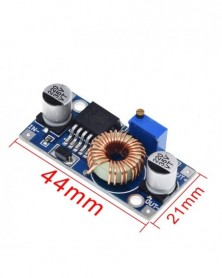
XL4005 DSN5000 Beyond LM2596 DC-DC állítható fokozatmentesen 5A tápegység modul, 5A nagy áram Nagy teljesítmény
86 Ft 215 FtApplication areas:
DIY mobile power supply, vehicle power supply, communication equipment power supply, etc.
Technical Parameters:
Model Name: DC-DC 5A High Current Buck Power Module
Module nature: non-isolated buck
Rectification mode: asynchronous rectification
Input voltage: 5V-32V
Output voltage: 0.8V-24V
Output current: peak 5A (3.5A or more work to strengthen heat dissipation)
Conversion efficiency: up to 90%
Switching frequency: 300KHz
Output ripple: 30mV (when no load)
Load adjustment rate: ±0.5%
Voltage regulation rate: ±2.5%
Operating temperature: -40 ° C to 85 ° C
Peripheral size: 43*21*14 (length * width * height) (mm)
Features: High-power magnetic surround inductor and high-current control chip, small size, high power and high efficiency. -
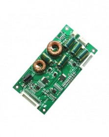
CA-288 univerzális 26-55 hüvelykes LED LCD TV háttérvilágítású illesztőprogram panel TV erősítő lemez állandó
249 Ft 622 Ftvin: 19-45V DC
vout: 60-165V automatic adaptation
Constant current output: 200mA
The current can be adjusted according to actual needs
Structure size: length 120mm, width 60mm, height 11mm
Purpose: used for 26 inch -55 inch LED TV monitor, voltage exceeding 100V and below 165V
Input voltage range: 19-45V DC Output voltage range: 60-165V DC
Output current: 10MA-1000MA can be set
Before you buy, you should understand the following important information:
1. The working voltage of the light bar must be any voltage between 60V-165. It cannot be lower than 60V. If it is lower than 60V, you can choose to buy other products in our store. It cannot be higher than 165V. The design limit working voltage of this product should not be higher than 165V. If this voltage is exceeded, the screen will be dark or the lamp will flicker. This product only has a constant current, not a constant voltage. The voltage will be automatically adjusted to the corresponding voltage according to the required voltage of the light bar, so you don't need to worry about how many volts are measured when there is no load.
2. In view of the fact that many buyers have bought and modified, and the parameters of the machine that need to be modified are unknown, so here is a statement: The quality and performance of the products sold in this shop are absolutely correct, but there is no guarantee that the goods you buy are The fact that it will be able to successfully light up. There are many reasons that may lead to non-matching. Voltage, power supply, connection, structure, etc. may all cause mismatch.
3. Conventional parameters: 60V-160V 200MA@ 24VIN
4. Problems that may be encountered when lighting up correctly:
1. The brightness is not enough, and the screen is obviously darker than the original board. At this time, start from two aspects. First, after connecting the dimming foot, try to use the remote control to adjust the brightness to see if it can be solved. If it can't be solved, test the actual The voltage of the pin, [Note: The brightness of my product is 0V, and the brightness is dark when the voltage is high. 】If the voltage range of the analog voltage mode is between 0V-5V or 0V-3.3V, if the voltage is always at a high voltage and cannot be reduced, this should be adjusted. If it is a PWM signal, the voltage is stable at 3.3V. At this time, if it is turned on and still does not meet the requirements, the second solution must be implemented. Second, adjust the resistance on the board to increase the current to meet the requirements.
5. In view of the fact that many buyers do not understand the topology of the LED driver board, the lack of understanding of its working principle directly leads to the consequences of not being able to use it correctly! Hereby, our company briefly introduces the current popular topology schemes. There are mainly three commonly used topologies: boost, buck, and boost-buck.
1. Boost topology means boost type. Interpretation: When using a constant current board with this type of solution, the load voltage [Vout] must be higher than the power input voltage [Vin], and the ratio must be greater than 1:1.5, that is, if the input voltage is 12V, the LED string voltage must When the voltage is above 18V, the LED booster board can work normally. If the voltage of the LED string is slightly higher than VIN or lower than VIN, the situation will be that the LED lights up when the machine is powered on, and the driver board cannot be switched or dimmed. Consequences of control. 2. The advantage of the Boost scheme lies in its simple structure and high efficiency. The disadvantage is that the boost ratio is limited, and the general boost ratio is 2-4 times. When it exceeds 6 times, the switching loss increases sharply, the temperature of the switching device rises sharply, and the system stability deteriorates.
2. Buck topology means buck type. Interpretation: When the constant current board adopts this kind of solution, the load voltage [Vout] must be lower than the power input voltage [VIN], that is: if the input voltage is 12V, the voltage of the light bar should be lower than 12V, when it is 24VIN It must be lower than 24V. If the voltage of the LED strip is higher than VIN, it cannot be driven to light up. The advantage of the Buck scheme lies in its simple structure and slightly higher efficiency than the Boost scheme. The disadvantage is that only a small number of LEDs can be connected in series. When the power is large, there are too many groups in parallel, which is disadvantageous for the PCB layout of the LED backlight module with compact space.
3. Boost-buck topology means boost-buck type. Interpretation: This type of program also has the function of step-up and step-down. It has the working modes of the first two schemes. But the disadvantage is that the efficiency is low and it is not suitable for high power occasions.
The most widely used in the industry is the Boost solution, followed by Buck, and boost-buck is smaller. -
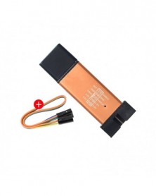
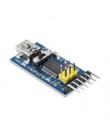
1Set ST LINK Stlink ST-Link V2 Mini STM8 STM32 szimulátor letöltési programozó programozás fedő DuPont kábellel ST Link
200 Ft 501 Ft1. Support the full range of STM32 SWD interface debugging, simple interface (including power supply), 4 line speed, stable work; Interface definition shell directly address! Don\\\\\\\'t need to read instructions!
2, support all series STM8 SWIM download debugging (common development environment such as IAR, STVD etc.) are supported. Support the software version is as follows:
ST - LINK Utility 2.0 and above
STVD 2 and above
STVP 3.2.3 and above
IAR EWARM V6.20 and above
IAR EWSTM8 V1.30 and above
KEIL RVMDK V4.21 and above
3. Support the firmware upgrade automatically, to ensure that the ST company product support. When they leave the firmware has been upgraded to the latest V2. The J17. S4.
4. Increase the 5 v power output, the output it can protect the I/O port, not afraid of error cause damage of ST - LINK V2!
5. Easy interface to use pure copper plating 2.54 spacing horn, with 20 cm dupont line, can deal with different target board line sequence, flexible connection;
6. Use U disk aluminum alloy shell to protect the mainboard, convenient to carry, not afraid of static electricity, not afraid of tumbling.
1 x ST-Link V2 STM8 STM32 Emulator / Download / Programmer
1 x dupont cable -
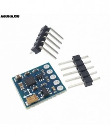
GY-271 HMC5883L 3V-5V három 3 tengelyes mágneses tériránytű magnetométer érzékelő modul Arduino IIC kártyához
114 Ft 286 FtDescription:
Note: It is Domestic Chip HMC5883, the program is not compatible with the original imported chip program, we can provide Matching routine !
1. Immersion Gold PCB, machine welding process to ensure quality.
2. Name: HMC5883L module (three-axis magnetic field module).
3. Use the chip: HMC5883L.
4. Power supply :3-5v.
5. Communication modes: standard IIC communication protocol.
6. Measuring range: ± 1.3-8 Gauss.
Package Included:
1PCS X GY-271 HMC5883L 3V-5V Triple Axis Compass Magnetometer Sensor Module For Arduino -
-
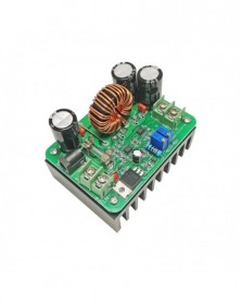
600 W-os Boost Step-up - 600 W-os Boost modul Tápellátás DC-DC fokozás Állandó áramfeszültség 9v-60V-12v-80V 48V 72V
880 Ft 2 201 FtDescription:
Size :85*63*64mm
Input voltage : 10V -60V
Input Current: Maximum input current of 15A
Output voltage : 12V -80V continuously adjustable
Output current: maximum output current of 10A ( adjustable )
Output power: the effective power P = input voltage V * 10A
Conversion efficiency: up to 95% ( input voltage, current; output voltage and current impact of conversion efficiency )
Short circuit protection : Fuse
Package:
1PCS 600W Boost Converter Step Up Module Power Supply DC DC 10V 60V 15A to 12V 80V 10 -
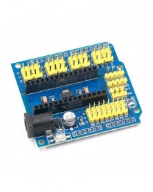
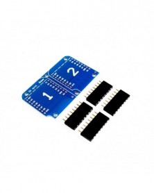
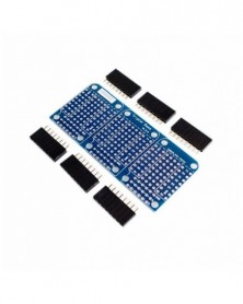
NANO V3.0 Adapter Prototype Shield és UNO többcélú bővítőkártya arduino-hoz
97 Ft 243 FtMultiple Extension Module Use Yellow Pin For Arduino NANO UNO
Description:
The expansion board specifically for Arduino NANO tailored, two rows stitch welding, can be used in for Arduino duemilanove 2009, UNO R1.
Package Included:
1 * Multiple extension module -
-
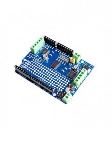
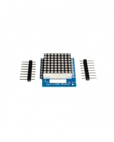
hivatalos IIC I2C TB6612 Mosfet léptetőmotor PCA9685 PWM szervovezérlő pajzs V2 Arduino Robot PWM Uno Mega R3 Cserélje ki
726 Ft 1 815 FtMake your own motor party with a motor shield and a fine assortment of motors!
The original L293D Motorshield kit is one of our most beloved kits, We kept the ability to drive up to 4 DC motors or 2 stepper motors, but added many improvements:
Instead of a L293D darlington driver, we now have the TB6612 MOSFET driver: with 1.2A per channel and 3A peak current capability. It also has much lower voltage drops across the motor so you get more torque out of your batteries, and there are built-in flyback diodes as well.
Instead of using a latch and the for Arduino's PWM pins, we have a fully-dedicated PWM driver chip onboard. This chip handles all the motor and speed controls over I2C. Only two pins (SDA & SCL) are required to drive the multiple motors, and since it's I2C you can also connect any other I2C devices or shields to the same pins. This also makes it drop-in compatible with any for Arduino.
Completely stackable design: 5 address-select pins means up to 32 stackable shields: that's 64 steppers or 128 DC motors! What on earth could you do with that many steppers? I have no idea but if you come up with something send us a photo because that would be a pretty glorious project.
Tested compatible with for Arduino UNO, for Leonardo, for ADK/Mega R3, Due, Diecimila & Duemilanove. Works with Mega/ADK R2 and earlier with 2 wire jumpers.
Package Included:
1 x Standard I2C TB6612 Mosfet Stepper Motor PCA9685 PWM Servo Driver Shield V2 For Arduino Robot Uno Mega R3 -
cnc shield v3 gravírozógép / 3D nyomtató / 4db A4988 illesztőprogram bővítőkártya Arduino-hoz
304 Ft 761 Ftproduct description:
The expansion board is used as a drive expansion board, which can be used for engraving machines and 3D printers.
It has four slots, which can drive four A4988 stepper motors. Each road stepper motor only needs two IO ports. In other words, six IO ports can manage three stepper motors well. It is very convenient to use.
Introduction of UNO for module IO port communication:
IO corresponds to the picture above:
UNO ---------------------Expansion Committee
8 ------------------------ EN (stepping motor driver enable, active low)
7 ----------------------- Z.DIR (Z-axis direction control)
6 ----------------------- Y.DIR (Y-axis direction control)
5 ----------------------- X.DIR (X-axis direction control)
4 ---------------------- Z.STEP (Z-axis stepping control)
3 ---------------------- Y.STEP (Y-axis stepping control)
2 ---------------------- X.STEP (X-axis stepping control)
//The following is a simple stepper motor control program,
#define EN 8 //Stepper motor is enabled, active low
#define X_DIR 5 // X -axis stepper motor direction control
#define Y_DIR 6 // y -axis stepper motor direction control
#define Z_DIR 7 // z-axis stepper motor direction control
#define X_STP 2 / / x -axis step control
#define Y_STP 3 / / y -axis step control
#define Z_STP 4 // z -axis step control
/ *
//Function: steps. Function: Control the direction and number of steps of the stepper motor.
//Parameter: dir direction control, dirPin corresponds to the DIR pin of the stepper motor, stepperPin corresponds to the "step" pin of the stepper motor, the number of steps has no return value.
* /
void step (boolean dir, byte dirPin, byte stepperPin, int steps)
{
digitalWrite(dirPin, dir);
Delay (50);
for(int i = 0; i
digitalWrite(stepperPin, HIGH);
delayMicroseconds(800);
digitalWrite(stepperPin, LOW);
delayMicroseconds(800);
}
}
void setup(){/ / The stepper motor used in the IO pin is set to output
pinMode (X_DIR, OUTPUT); pinMode (X_STP, OUTPUT);
pinMode (Y_DIR, OUTPUT); pinMode (Y_STP, OUTPUT);
pinMode (Z_DIR, OUTPUT); pinMode (Z_STP, OUTPUT);
pinMode (EN, OUTPUT);
digitalWrite(EN, LOW);
}
void loop() {
step (false, X_DIR, X_STP, 200); // X-axis motor reverses 1 cycle, 200 steps are a circle.
step(false, Y_DIR, Y_STP, 200); // The y-axis motor reverses 1 cycle, and 200 steps are a circle.
step (false, Z_DIR, Z_STP, 200); // The z-axis motor reverses 1 cycle, and 200 steps are a circle.
Delay (1000);
step(true, X_DIR, X_STP, 200); // X axis motor advances 1 circle, 200 steps is one circle.
step(true, Y_DIR, Y_STP, 200); // The y-axis motor advances 1 circle, 200 steps are one circle.
step(true, Z_DIR, Z_STP, 200); // The z-axis motor advances 1 circle, 200 steps are one circle.
Delay (1000);
}
Shipping list:
1 X cnc shield v3
4 X A4988
4 X Heatsink
-
-
-
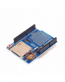
XD-204 adatnaplózó modul naplózó rögzítő pajzs V1.0 Arduino UNO SD kártyához
111 Ft 278 FtDescription:
SD card interface works with FAT16 or FAT32 formatted cards. 3.3v level shifter circuitry prevents damage to your SD card
Real time clock (RTC) keeps the time going even when for Arduino is unplugged. The battery backup lasts for years
Included libraries and example code for both SD and RTC mean you can get going quickly Prototyping area for solderingconnectors, circuitry or sensors.
Onboard 3.3v regulator is both a reliable reference voltage and also reliably runs SD cards that require a lot of power to run
Works for Arduino UNO, Duemilanove, Diecimila, Leonardo or ADK/Mega R3 or higher. ADK/Mega R2 or lower are not supported
Size:68x53x23mm(approx) -
-
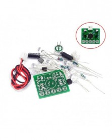
Elektronikus Vicces készlet Hangvezérlés Dallamlámpa LED Melody Light DIY Production Suite Oktató elektronikai készletek
62 Ft 155 FtName: Voice-activated LED melody light;
Working voltage: 3-5.5V
PCB board: FR-4 A grade glass fiber board
Dimensions: 3CM*2.3CM
Circuit function:
After the kit is successfully produced, 5 LEDs will flash with the rhythm of music or other sounds, and they can be placed near the speaker, allowing the lights to accompany the music to dance!
The voice-activated LED melody light is mainly composed of a power supply circuit, a microphone amplifier circuit, and an LED light-emitting circuit. The power is input by J1, and C1 is filtered for circuit use. MIC1 converts sound signals into electrical signals, which are amplified by C2 coupled to Q1, and the amplified signals are sent to the base of Q2. Q2 drives 5 LEDs to emit light. The louder the sound, the brighter the LED lights. -
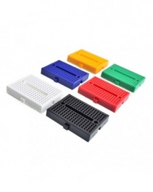
Piros - 1 DB SYB-170 mini forrasztás nélküli prototípus kenyértábla 170 csatlakozási ponttal rendelkező PCB teszttábla
58 Ft 146 FtSeven colors : red, blue, yellow, green, white and black.
With self-adhesive tape on the back, make it easy to stick on the Prototype Shield.
We have always cared about the customer experience and improve the product function details.
Product Specifications and Package details:
Board Material: White ABS plastic with black legend
Internal Contacts Material: Phosphor bronze finished.
Board Base: Self-Adhesive Tape
170 tie-points total: 2 columns of 17 lanes with two 5 point rows each column.
Socket Pitch: 0.1"
Contact Type: Mixed metal strips
Extension Clips: Yes (Can extend with other boards)
Dimension: 45mm x 34.5mm x 9.5mm
Package included: 1pcs 170 tie-points breadboard
Convenient and Easy-to-use:
Solderless breadboard is convenient for the prototypes and circuit design experiment and other DIY projects.
Each row and columns has corresponding letters and numbers.
Self-adhesive back tape makes it easy to stick on a platform, such as the duino prototype shield.
With tight plug-in contacts, the components will sit well after assembly therefore there are no wobbles.
Jumper wires are easy to insert into or remove from these breadboards.
With nubbins and slots on the sides to easily connect multiple breadboards together.
Thoughtful Product Features:
Perfect shield prototyping and testing; can be applied in debugging without welding.
Fit for 21-26 AWG (0.4-0.7MM) wire. Comparing with breadboards of high AWG wire, Elegoo breadboards is of higher physical strength and lower resistance.
The solderless breadboards do not require soldering, therefore they are completely re-usable. This makes it easy to use for creating temporary prototypes and experimenting with circuit design which is a construction base for prototype of electronics.
Compatible with resistors, transistors, diodes, LEDS, capacitors and other types of electronic components -
-
-
-
A Tiny RTC I2C modulok 24C32 memória DS1307 óra RTC modul arduno-hoz (akkumulátor nélkül)
55 Ft 138 FtFeatures:
This module is without battery(battery type is LIR2032) ,because we received the notice from the post office that they don\'t accecpt goods with batteries.Therefore,please buy cautiously.
This is the DS1307 Real Time Clock developed by one of our designer waiman. The module comes fully assembled and pre-programmed with the current time (ok, so it\'s our current time - MST). The DS1307 is accessed via the I2C protocol.
Two wire I2C interface
Hour : Minutes : Seconds AM/PM
Day Month, Date - Year
Size: 28x25x10mm
Leap year compensation
Accurate calendar up to year 2100
1Hz output pin
56 Bytes of Non-volatile memory available to user
Packing content:
1 x DS1307 Time Clock Module