Huzal, kábel és vezeték
-
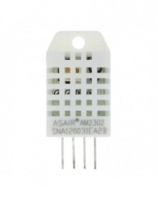
Szín: DHT22 - 1 db DHT22 digitális hőmérséklet- és páratartalom-érzékelő, AM2302 hőmérséklet- és páratartalom
470 Ft 810 FtProduct parameters:
Humidity measurement range: 0% to 99.9% (0°C-50°C range)
Humidity measurement error: ±2%
Temperature measurement range: -40 ° C ~ 80 ° C
Temperature measurement error: ±0.5°C max ±1°C
Resolution: 16 bits
Sampling period: 2s
Working voltage: 3V--5.5V -
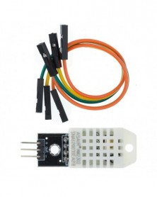
Szín: DHT22 modul - 1 DB DHT22 digitális hőmérséklet- és páratartalom-érzékelő, AM2302 hőmérséklet- és
429 Ft 739 FtProduct parameters:
Humidity measurement range: 0% to 99.9% (0°C-50°C range)
Humidity measurement error: ±2%
Temperature measurement range: -40 ° C ~ 80 ° C
Temperature measurement error: ±0.5°C max ±1°C
Resolution: 16 bits
Sampling period: 2s
Working voltage: 3V--5.5V -
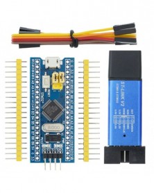
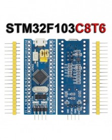
Szín: C6T6 STLINK V2 - STM32F103C6T6 STM32F103C8T6 ARM STM32 Minimális rendszerfejlesztő kártyamodul Arduino ST-LINK V2
593 Ft 1 022 FtSTM32F103C8T6 VS STM32F103C6T6
STM32F103C8T6 ARM STM32 Minimum System Development Board Module For Arduino
This is a core chip based on for CS32F103C8T6 ARM core board, features are as follows:
1, the board based on the most basic MCU circuit, 8M and 32768 crystal circuit, USB power supply circuit.
2, the core board is divided into two rows leads to all the I / O port.
3, with SWD simulation debug download interface, simple and convenient, debugging speed.
4, the use of the Mirco USB interface, you can do USB communication and power supply, USB interface, compatible with the ordinary Andrews mobile phone charger interface.
6, RTC crystal Epson brand, easy to start, more stable.
7, with double pin, but the pin does not default welding, the user according to their own application scenarios to choose their own welding direction. If welding is required, please tell the owner.
Keil can be used to compile, IAR compiler, can be downloaded through the J-Link or USART1 procedures, the procedures are the owner and debugging procedures, there are problems can consult the owner.
Chip Description:
1, 32F103C8T6
Package Type: LQFP;
Number of pins: 48;
Kernel: Cortex-M3;
Operating frequency: 72MHz;
Storage resources: 64K Byte Flash, 20KByte SRAM;
Interface Resources: 2x SPI, 3x USART, 2x I2C, 1x CAN, 37x I / O ports,
Analog-to-digital conversion: 2x ADC (12-bit / 16-channel)
Timers: 3 general timers and 1 advanced timer
Debug Download: Support JTAG / SWD debug interface to download, support for IAP.
2, RT9193: 3.3V regulator chip, the maximum output of 300mA.
Interface description:
1, SWD interface: support for simulation, download and debug.
2, Mirco USB interface: power supply and USB communication, does not support the download.
3, USART1 interface: USART1 can be used to download the program, or use the USART1 for communication.
4, MCU pin interface: leads all I / O port pins, easy to connect with peripherals.
5, 5V and 3.3V power input and output interface: commonly used in external power supply, or with other modules for common ground treatment
Other Device Description:
1, Power LED (PWR): Power indicator status, can determine whether the power supply is stable.
2, the user LED (PC13): to facilitate the I / O output test or indicate the program running.
3, start jumping choose programming mode: (1, the user flash memory 2, SRAM 3, system memory).
4, reset button: reset chip for the user program.
5, 8M Crystal: The frequency can be set to make the system clocked at 72MHz.
6,32.768KHz Crystal: Available for built-in RTC, or for calibration.
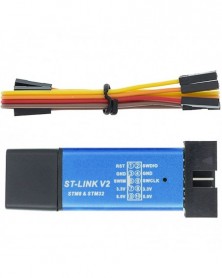
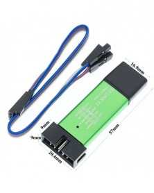
ST-Link V2 Mini STM8 Simulator Download
Specifications
l Input voltage (USB): 5V
l Output Voltages: 3.3V, 5V
l Interfaces: SWIM, SWD
l Connectors: USB, 10 pin (molex type)
l Dimensions: 57mm x 20mm x 8mm[2.2in x 0.7in x 0.3in]
The St Link V2 programmer supports STM8 and STM32 microcontrollers
The module supports automatic firmware upgrades to ensure the maintenance of ST products. The factory firmware has been updated to the latest version V2.J17.S4.
2x5 headers 2.54 mm (0.1 in) apart, including cables (4 f-f jumper wires)
USB 2.0 full speed compatible interface
l WARNING: STM32 chips run on 3.3V, most breakout boards will include a voltage regulator so it can be powered from USB, and STLink dongles will provide a 3.3V VCC pin to power up the chip.
l Do not connect the board to the PC using USB while the chip is powered up using the ST-Link V2 programmer!
l Connect one or another but not both simultaneously. The ST-Link V2 dongle provides a 5V pin as well. It is not going to be used because the STM32 chips are not 5V tolerant, the 3.3V pin has to be used only.
Pinout
-
Szín: C8T6 STLINK V2 - STM32F103C6T6 STM32F103C8T6 ARM STM32 Minimális rendszerfejlesztő kártyamodul Arduino ST-LINK V2
679 Ft 1 171 FtSTM32F103C8T6 VS STM32F103C6T6
STM32F103C8T6 ARM STM32 Minimum System Development Board Module For Arduino
This is a core chip based on for CS32F103C8T6 ARM core board, features are as follows:
1, the board based on the most basic MCU circuit, 8M and 32768 crystal circuit, USB power supply circuit.
2, the core board is divided into two rows leads to all the I / O port.
3, with SWD simulation debug download interface, simple and convenient, debugging speed.
4, the use of the Mirco USB interface, you can do USB communication and power supply, USB interface, compatible with the ordinary Andrews mobile phone charger interface.
6, RTC crystal Epson brand, easy to start, more stable.
7, with double pin, but the pin does not default welding, the user according to their own application scenarios to choose their own welding direction. If welding is required, please tell the owner.
Keil can be used to compile, IAR compiler, can be downloaded through the J-Link or USART1 procedures, the procedures are the owner and debugging procedures, there are problems can consult the owner.
Chip Description:
1, 32F103C8T6
Package Type: LQFP;
Number of pins: 48;
Kernel: Cortex-M3;
Operating frequency: 72MHz;
Storage resources: 64K Byte Flash, 20KByte SRAM;
Interface Resources: 2x SPI, 3x USART, 2x I2C, 1x CAN, 37x I / O ports,
Analog-to-digital conversion: 2x ADC (12-bit / 16-channel)
Timers: 3 general timers and 1 advanced timer
Debug Download: Support JTAG / SWD debug interface to download, support for IAP.
2, RT9193: 3.3V regulator chip, the maximum output of 300mA.
Interface description:
1, SWD interface: support for simulation, download and debug.
2, Mirco USB interface: power supply and USB communication, does not support the download.
3, USART1 interface: USART1 can be used to download the program, or use the USART1 for communication.
4, MCU pin interface: leads all I / O port pins, easy to connect with peripherals.
5, 5V and 3.3V power input and output interface: commonly used in external power supply, or with other modules for common ground treatment
Other Device Description:
1, Power LED (PWR): Power indicator status, can determine whether the power supply is stable.
2, the user LED (PC13): to facilitate the I / O output test or indicate the program running.
3, start jumping choose programming mode: (1, the user flash memory 2, SRAM 3, system memory).
4, reset button: reset chip for the user program.
5, 8M Crystal: The frequency can be set to make the system clocked at 72MHz.
6,32.768KHz Crystal: Available for built-in RTC, or for calibration.
ST-Link V2 Mini STM8 Simulator Download
Specifications
l Input voltage (USB): 5V
l Output Voltages: 3.3V, 5V
l Interfaces: SWIM, SWD
l Connectors: USB, 10 pin (molex type)
l Dimensions: 57mm x 20mm x 8mm[2.2in x 0.7in x 0.3in]
The St Link V2 programmer supports STM8 and STM32 microcontrollers
The module supports automatic firmware upgrades to ensure the maintenance of ST products. The factory firmware has been updated to the latest version V2.J17.S4.
2x5 headers 2.54 mm (0.1 in) apart, including cables (4 f-f jumper wires)
USB 2.0 full speed compatible interface
l WARNING: STM32 chips run on 3.3V, most breakout boards will include a voltage regulator so it can be powered from USB, and STLink dongles will provide a 3.3V VCC pin to power up the chip.
l Do not connect the board to the PC using USB while the chip is powered up using the ST-Link V2 programmer!
l Connect one or another but not both simultaneously. The ST-Link V2 dongle provides a 5V pin as well. It is not going to be used because the STM32 chips are not 5V tolerant, the 3.3V pin has to be used only.
Pinout
-
Szín: STM32F103C6T6 - STM32F103C6T6 STM32F103C8T6 ARM STM32 Minimális rendszerfejlesztő kártyamodul Arduino ST-LINK V2
278 Ft 480 FtSTM32F103C8T6 VS STM32F103C6T6
STM32F103C8T6 ARM STM32 Minimum System Development Board Module For Arduino
This is a core chip based on for CS32F103C8T6 ARM core board, features are as follows:
1, the board based on the most basic MCU circuit, 8M and 32768 crystal circuit, USB power supply circuit.
2, the core board is divided into two rows leads to all the I / O port.
3, with SWD simulation debug download interface, simple and convenient, debugging speed.
4, the use of the Mirco USB interface, you can do USB communication and power supply, USB interface, compatible with the ordinary Andrews mobile phone charger interface.
6, RTC crystal Epson brand, easy to start, more stable.
7, with double pin, but the pin does not default welding, the user according to their own application scenarios to choose their own welding direction. If welding is required, please tell the owner.
Keil can be used to compile, IAR compiler, can be downloaded through the J-Link or USART1 procedures, the procedures are the owner and debugging procedures, there are problems can consult the owner.
Chip Description:
1, 32F103C8T6
Package Type: LQFP;
Number of pins: 48;
Kernel: Cortex-M3;
Operating frequency: 72MHz;
Storage resources: 64K Byte Flash, 20KByte SRAM;
Interface Resources: 2x SPI, 3x USART, 2x I2C, 1x CAN, 37x I / O ports,
Analog-to-digital conversion: 2x ADC (12-bit / 16-channel)
Timers: 3 general timers and 1 advanced timer
Debug Download: Support JTAG / SWD debug interface to download, support for IAP.
2, RT9193: 3.3V regulator chip, the maximum output of 300mA.
Interface description:
1, SWD interface: support for simulation, download and debug.
2, Mirco USB interface: power supply and USB communication, does not support the download.
3, USART1 interface: USART1 can be used to download the program, or use the USART1 for communication.
4, MCU pin interface: leads all I / O port pins, easy to connect with peripherals.
5, 5V and 3.3V power input and output interface: commonly used in external power supply, or with other modules for common ground treatment
Other Device Description:
1, Power LED (PWR): Power indicator status, can determine whether the power supply is stable.
2, the user LED (PC13): to facilitate the I / O output test or indicate the program running.
3, start jumping choose programming mode: (1, the user flash memory 2, SRAM 3, system memory).
4, reset button: reset chip for the user program.
5, 8M Crystal: The frequency can be set to make the system clocked at 72MHz.
6,32.768KHz Crystal: Available for built-in RTC, or for calibration.
ST-Link V2 Mini STM8 Simulator Download
Specifications
l Input voltage (USB): 5V
l Output Voltages: 3.3V, 5V
l Interfaces: SWIM, SWD
l Connectors: USB, 10 pin (molex type)
l Dimensions: 57mm x 20mm x 8mm[2.2in x 0.7in x 0.3in]
The St Link V2 programmer supports STM8 and STM32 microcontrollers
The module supports automatic firmware upgrades to ensure the maintenance of ST products. The factory firmware has been updated to the latest version V2.J17.S4.
2x5 headers 2.54 mm (0.1 in) apart, including cables (4 f-f jumper wires)
USB 2.0 full speed compatible interface
l WARNING: STM32 chips run on 3.3V, most breakout boards will include a voltage regulator so it can be powered from USB, and STLink dongles will provide a 3.3V VCC pin to power up the chip.
l Do not connect the board to the PC using USB while the chip is powered up using the ST-Link V2 programmer!
l Connect one or another but not both simultaneously. The ST-Link V2 dongle provides a 5V pin as well. It is not going to be used because the STM32 chips are not 5V tolerant, the 3.3V pin has to be used only.
Pinout
-
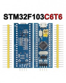
Szín: STM32F103C8T6 - STM32F103C6T6 STM32F103C8T6 ARM STM32 Minimális rendszerfejlesztő kártyamodul Arduino ST-LINK V2
361 Ft 623 FtSTM32F103C8T6 VS STM32F103C6T6
STM32F103C8T6 ARM STM32 Minimum System Development Board Module For Arduino
This is a core chip based on for CS32F103C8T6 ARM core board, features are as follows:
1, the board based on the most basic MCU circuit, 8M and 32768 crystal circuit, USB power supply circuit.
2, the core board is divided into two rows leads to all the I / O port.
3, with SWD simulation debug download interface, simple and convenient, debugging speed.
4, the use of the Mirco USB interface, you can do USB communication and power supply, USB interface, compatible with the ordinary Andrews mobile phone charger interface.
6, RTC crystal Epson brand, easy to start, more stable.
7, with double pin, but the pin does not default welding, the user according to their own application scenarios to choose their own welding direction. If welding is required, please tell the owner.
Keil can be used to compile, IAR compiler, can be downloaded through the J-Link or USART1 procedures, the procedures are the owner and debugging procedures, there are problems can consult the owner.
Chip Description:
1, 32F103C8T6
Package Type: LQFP;
Number of pins: 48;
Kernel: Cortex-M3;
Operating frequency: 72MHz;
Storage resources: 64K Byte Flash, 20KByte SRAM;
Interface Resources: 2x SPI, 3x USART, 2x I2C, 1x CAN, 37x I / O ports,
Analog-to-digital conversion: 2x ADC (12-bit / 16-channel)
Timers: 3 general timers and 1 advanced timer
Debug Download: Support JTAG / SWD debug interface to download, support for IAP.
2, RT9193: 3.3V regulator chip, the maximum output of 300mA.
Interface description:
1, SWD interface: support for simulation, download and debug.
2, Mirco USB interface: power supply and USB communication, does not support the download.
3, USART1 interface: USART1 can be used to download the program, or use the USART1 for communication.
4, MCU pin interface: leads all I / O port pins, easy to connect with peripherals.
5, 5V and 3.3V power input and output interface: commonly used in external power supply, or with other modules for common ground treatment
Other Device Description:
1, Power LED (PWR): Power indicator status, can determine whether the power supply is stable.
2, the user LED (PC13): to facilitate the I / O output test or indicate the program running.
3, start jumping choose programming mode: (1, the user flash memory 2, SRAM 3, system memory).
4, reset button: reset chip for the user program.
5, 8M Crystal: The frequency can be set to make the system clocked at 72MHz.
6,32.768KHz Crystal: Available for built-in RTC, or for calibration.
ST-Link V2 Mini STM8 Simulator Download
Specifications
l Input voltage (USB): 5V
l Output Voltages: 3.3V, 5V
l Interfaces: SWIM, SWD
l Connectors: USB, 10 pin (molex type)
l Dimensions: 57mm x 20mm x 8mm[2.2in x 0.7in x 0.3in]
The St Link V2 programmer supports STM8 and STM32 microcontrollers
The module supports automatic firmware upgrades to ensure the maintenance of ST products. The factory firmware has been updated to the latest version V2.J17.S4.
2x5 headers 2.54 mm (0.1 in) apart, including cables (4 f-f jumper wires)
USB 2.0 full speed compatible interface
l WARNING: STM32 chips run on 3.3V, most breakout boards will include a voltage regulator so it can be powered from USB, and STLink dongles will provide a 3.3V VCC pin to power up the chip.
l Do not connect the board to the PC using USB while the chip is powered up using the ST-Link V2 programmer!
l Connect one or another but not both simultaneously. The ST-Link V2 dongle provides a 5V pin as well. It is not going to be used because the STM32 chips are not 5V tolerant, the 3.3V pin has to be used only.
Pinout
-
Szín: ST-LINK V2 - STM32F103C6T6 STM32F103C8T6 ARM STM32 Minimális rendszerfejlesztő kártyamodul Arduino ST-LINK V2
396 Ft 683 FtSTM32F103C8T6 VS STM32F103C6T6
STM32F103C8T6 ARM STM32 Minimum System Development Board Module For Arduino
This is a core chip based on for CS32F103C8T6 ARM core board, features are as follows:
1, the board based on the most basic MCU circuit, 8M and 32768 crystal circuit, USB power supply circuit.
2, the core board is divided into two rows leads to all the I / O port.
3, with SWD simulation debug download interface, simple and convenient, debugging speed.
4, the use of the Mirco USB interface, you can do USB communication and power supply, USB interface, compatible with the ordinary Andrews mobile phone charger interface.
6, RTC crystal Epson brand, easy to start, more stable.
7, with double pin, but the pin does not default welding, the user according to their own application scenarios to choose their own welding direction. If welding is required, please tell the owner.
Keil can be used to compile, IAR compiler, can be downloaded through the J-Link or USART1 procedures, the procedures are the owner and debugging procedures, there are problems can consult the owner.
Chip Description:
1, 32F103C8T6
Package Type: LQFP;
Number of pins: 48;
Kernel: Cortex-M3;
Operating frequency: 72MHz;
Storage resources: 64K Byte Flash, 20KByte SRAM;
Interface Resources: 2x SPI, 3x USART, 2x I2C, 1x CAN, 37x I / O ports,
Analog-to-digital conversion: 2x ADC (12-bit / 16-channel)
Timers: 3 general timers and 1 advanced timer
Debug Download: Support JTAG / SWD debug interface to download, support for IAP.
2, RT9193: 3.3V regulator chip, the maximum output of 300mA.
Interface description:
1, SWD interface: support for simulation, download and debug.
2, Mirco USB interface: power supply and USB communication, does not support the download.
3, USART1 interface: USART1 can be used to download the program, or use the USART1 for communication.
4, MCU pin interface: leads all I / O port pins, easy to connect with peripherals.
5, 5V and 3.3V power input and output interface: commonly used in external power supply, or with other modules for common ground treatment
Other Device Description:
1, Power LED (PWR): Power indicator status, can determine whether the power supply is stable.
2, the user LED (PC13): to facilitate the I / O output test or indicate the program running.
3, start jumping choose programming mode: (1, the user flash memory 2, SRAM 3, system memory).
4, reset button: reset chip for the user program.
5, 8M Crystal: The frequency can be set to make the system clocked at 72MHz.
6,32.768KHz Crystal: Available for built-in RTC, or for calibration.
ST-Link V2 Mini STM8 Simulator Download
Specifications
l Input voltage (USB): 5V
l Output Voltages: 3.3V, 5V
l Interfaces: SWIM, SWD
l Connectors: USB, 10 pin (molex type)
l Dimensions: 57mm x 20mm x 8mm[2.2in x 0.7in x 0.3in]
The St Link V2 programmer supports STM8 and STM32 microcontrollers
The module supports automatic firmware upgrades to ensure the maintenance of ST products. The factory firmware has been updated to the latest version V2.J17.S4.
2x5 headers 2.54 mm (0.1 in) apart, including cables (4 f-f jumper wires)
USB 2.0 full speed compatible interface
l WARNING: STM32 chips run on 3.3V, most breakout boards will include a voltage regulator so it can be powered from USB, and STLink dongles will provide a 3.3V VCC pin to power up the chip.
l Do not connect the board to the PC using USB while the chip is powered up using the ST-Link V2 programmer!
l Connect one or another but not both simultaneously. The ST-Link V2 dongle provides a 5V pin as well. It is not going to be used because the STM32 chips are not 5V tolerant, the 3.3V pin has to be used only.
Pinout
-
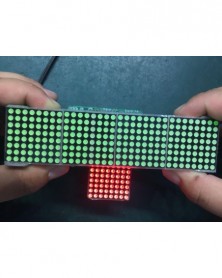
Piros szín - MAX7219 pontmátrix modul mikrokontroller modul 4 az 1-ben kijelző C14 piros/zöld Arduinohoz
469 Ft 809 FtMAX7219 dot matrix module microcontroller module 4 in one display
MAX7219 Display Panel Dot Matrix Module Microcontroller 4 In One Display with 5P Line 4 in 1 Red Green for Arduino diy kit
A single module can drive a 8x8 dot matrix common cathode
Operating Voltage: 5V
A single module can drive a 8x8 dot matrix common cathode
Operating Voltage: 5V
Dimensions: 12.8X12.8X1.3cm/
Fixing screws with 64 holes with a diameter 3mm
Module with input and output interfaces, support for cascading multiple modules
Quality:1Set
The left side of the module to the input port, the right to an output port
When the control of a single module, simply input port connected to CPU
When a plurality of cascaded modules, input and output termination CPU, an input terminal of the second output end of the first module a module, the first two modules of the input terminal of the three termination modules, and so on...
51 microcontrollers, for example:
VCC 5V
GND GND
DIN P2.2
CS P2.1
CLK P2.0
Size for manual measurement, there may be a 0 to 2 cm error, belongs to the normal phenomenon.
And due to the difference between different monitors, the picture may not reflect the actual color of the item. Thank you! -
Szín: zöld - MAX7219 pontmátrix modul mikrokontroller modul 4 az 1-ben kijelző C14 piros/zöld Arduinohoz
532 Ft 917 FtMAX7219 dot matrix module microcontroller module 4 in one display
MAX7219 Display Panel Dot Matrix Module Microcontroller 4 In One Display with 5P Line 4 in 1 Red Green for Arduino diy kit
A single module can drive a 8x8 dot matrix common cathode
Operating Voltage: 5V
A single module can drive a 8x8 dot matrix common cathode
Operating Voltage: 5V
Dimensions: 12.8X12.8X1.3cm/
Fixing screws with 64 holes with a diameter 3mm
Module with input and output interfaces, support for cascading multiple modules
Quality:1Set
The left side of the module to the input port, the right to an output port
When the control of a single module, simply input port connected to CPU
When a plurality of cascaded modules, input and output termination CPU, an input terminal of the second output end of the first module a module, the first two modules of the input terminal of the three termination modules, and so on...
51 microcontrollers, for example:
VCC 5V
GND GND
DIN P2.2
CS P2.1
CLK P2.0
Size for manual measurement, there may be a 0 to 2 cm error, belongs to the normal phenomenon.
And due to the difference between different monitors, the picture may not reflect the actual color of the item. Thank you! -
Szín: PLATÓ-170 - 170 Wishful Clamp Barkácsfogó Elektronikus fogó Átlós fogó Wishful Clamp
317 Ft 547 FtFeatures:
100% quality and Brand new.
Spring loaded for easy use
Automatic rebound function
45degangle use in tight spaces
Carbon steel hardening treatment
Light weight, thin profile and easy handling insulate grips comfortable for operation
Feel comfortable and convenient to use
Special suitable for cut wire, electronic feet, trimming plastic products, cut a small metal wire, and so on Used in electronic industry repair, jewelry processing, model making and fishing, etc
Specification:
Color: Blue
Material: Stainless steel jaw, Anti-slip rubber handle
Length: 12mm
Packing list :
1x Cable cutter (no retail box) -
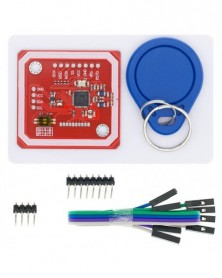
Szín: PN532 - PN532 NFC RFID modul V3, NFC Android telefon RFID kiterjesztéssel, séma és könyvtár
484 Ft 834 FtFeature :
1.Gilt PCB and Small dimension and easy to embed into your project
2.Support I2C.SPI and HSU (High Speed UART), Change between those modes
3.Support RFID reading and writing
SupportP2P communication with peers
Support NFC with Android phone
4.Typical Operating Distance have been updated to 5cm~7cm reading distance
5.Work in NFC Mode or RFID reader/writer Mode
6.RFID reader/writer supports:
1) 1k, 4k, Ultralight, and DesFire cards
2) ISO/IEC 14443-4 cards such as CD97BX, CD light, Desfire, P5CN072 (SMX)
3) Innovision Jewel cards such as IRT5001 card
4) FeliCa cards such as RCS_860 and RCS_854
7.Plug and play, for compatible
8.Built in PCB Antenna, with 4cm~6cm communication distance
9.On-board level shifter, Standard 5V TTL for I2C and UART, 3.3V TTL SPI
10.Work as RFID reader/writer
11.Work as 1443-A card or a virtual card
12.Exchange data with other NFC devices such as smartphone -
1 db ESP32-DevKitC alaplap ESP32 V4 fejlesztőkártya ESP32-WROOM-32D
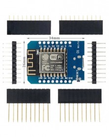
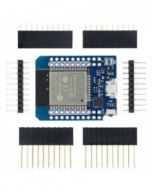
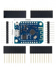
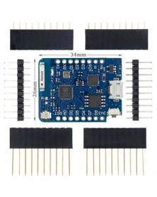
475 Ft 819 FtESP32-DevKitC V4 Getting Started Guide [] This guide shows how to start using the ESP32-DevKitC V4 development board. For description of other versions of ESP32-DevKitC check ESP32 Hardware Reference. What You Need ESP32-DevKitC V4 board USB A / micro USB B cable Computer running Windows, Linux, or macOS You can skip the introduction sections and go directly to Section Start Application Development. Overview ESP32-DevKitC V4 is a small-sized ESP32-based development board produced by Espressif. Most of the I/O pins are broken out to the pin headers on both sides for easy interfacing. Developers can either connect peripherals with jumper wires or mount ESP32-DevKitC V4 on a breadboard. To cover a wide range of user requirements, the following versions of ESP32-DevKitC V4 are available: different ESP32 modules ESP32-WROOM-32 ESP32-WROOM-32D ESP32-WROOM-32U ESP32-SOLO-1 ESP32-WROVER ESP32-WROVER-B ESP32-WROVER-I ESP32-WROVER-B (IPEX) male or female pin headers. For details please refer to Espressif Product Ordering Information. Functional Description The following figure and the table below describe the key components, interfaces and controls of the ESP32-DevKitC V4 board.
Power Supply Options There are three mutually exclusive ways to provide power to the board: Micro USB port, default power supply 5V / GND header pins 3V3 / GND header pins Warning The power supply must be provided using one and only one of the options above, otherwise the board and/or the power supply source can be damaged. Note on C15 The component C15 may cause the following issues on earlier ESP32-DevKitC V4 boards: The board may boot into Download mode If you output clock on GPIO0, C15 may impact the signal In case these issues occur, please remove the component. The figure below shows C15 highlighted in yellow. -
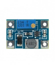
10db Smart Electronics DC-DC SX1308 Step-UP állítható teljesítménymodul Step Up Boost Converter 2-24V-2-28V 2A
458 Ft 790 FtDescription:
SX1308 booster module carrying SX1308 chip, its packagnig is small, and high efficiency. The output power can be adjust, maximum can arrive 28V and its interior integrate the lowest RDS internal resistance 100mΩ metal oxide semiconductor field effect transistor (mosfet), which can realize large current output of up to 2A. It widely used in 3G network products, digital products, mobile power supply,battery power supply, equipment, etc.
Features:
Oscillation frequency 1.2MHz
efficiency is as high as 95%
Circuit has short circuit protection, overheating protection function
10k to adjust potentiometer, adjust the output voltage
Parameters:
Maximum input voltage: DC 2-24V
Maximum output voltage: DC 2-28V
Switching frequency: 1.2MHz
Maximum current output: 2A
Note : any questions, turn the potentiometer in one direction more than 10 rotations for try -
1db Smart Electronics DC-DC SX1308 Step-UP állítható teljesítménymodul Step Up Boost Converter 2-24V-2-28V 2A
113 Ft 194 FtDescription:
SX1308 booster module carrying SX1308 chip, its packagnig is small, and high efficiency. The output power can be adjust, maximum can arrive 28V and its interior integrate the lowest RDS internal resistance 100mΩ metal oxide semiconductor field effect transistor (mosfet), which can realize large current output of up to 2A. It widely used in 3G network products, digital products, mobile power supply,battery power supply, equipment, etc.
Features:
Oscillation frequency 1.2MHz
efficiency is as high as 95%
Circuit has short circuit protection, overheating protection function
10k to adjust potentiometer, adjust the output voltage
Parameters:
Maximum input voltage: DC 2-24V
Maximum output voltage: DC 2-28V
Switching frequency: 1.2MHz
Maximum current output: 2A
Note : any questions, turn the potentiometer in one direction more than 10 rotations for try -
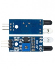
Szín: DIY KIT - Patch infravörös tolatóradar készlet barkácsolás elektronikus gyártási tartomány érzékelő
264 Ft 455 FtShipment is in loose parts! I need friends to solder it by myself.
Working voltage: DC9V Board size: 70*45mm
1. Product description
The infrared reversing radar is composed of multiple resonance circuits, infrared signal transmitting and receiving circuits, infrared signal amplification and voltage comparison circuits. It has the characteristics of simple circuit, low cost, and stable circuit operation. It is widely used in various ranging applications.
2. Installation and debugging and simple principle description
1. The infrared transmitting tube HF and the infrared receiving tube HJ have polarity (the long leg is positive), please do not install it wrongly, the installation direction can be upwards or sideways. RP1 adjusts the reflection distance and RP2 adjusts the sensitivity. You can try to turn on LED3 at a distance of 30cm, LED2 and LED3 at a distance of 20cm, and all on at a distance of 10cm. It is better to use white paper to block the reflection above the infrared sensor. This product is a teaching kit, not an industrial device. It is used for learning, teaching, and hobbies. Please know.
2. The time base circuit NE555 and surrounding components form a multivibrator to generate an infrared wave signal, which is output through IC2's third pin and drives the infrared transmitter tube HF to emit an infrared signal. -
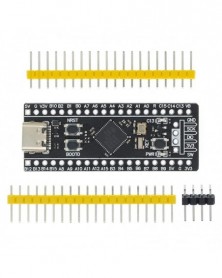
Szín: STM32F401 - STM32F401 STM32F411 Fejlesztőkártya V3.0 STM32F401CCU6 STM32F411CEU6 STM32F4 Oktatótábla 84Mhz 64KB RAM
370 Ft 638 Ft
STM32F401CCU6 3.0/STM32F411CEU6 3.0 Development Board
STM32F401CCU6 core board V3.0
Freq. 84Mhz ROM:256KB RAM:64KB
STM32F411CEU6 core board V3.0
Freq. 100MHZ ROM:512KB RAM:128KB
Core Board Information
Baidu network disk is not recommended to download data, domestic code cloud is fast
Gitee code cloud information link: https://gitee.com/WeAct-TC/MiniF4-STM32F4x1.git
Github information link: https://github.com/WeActTC/MiniF4-STM32F4x1.git
Baidu network disk link: https://pan.baidu.com/s/1vW9H-q9C5n2yVAEp38pw5A
Extract code: gxnx
STM32 download and burn part of the tutorial: https://www.weact-tc.cn/2019/11/30/STM32Download/
Part of MicroPython tutorial: https://www.weact-tc.cn/2020/01/01/micropython/
MicroPython compilation information: https://github.com/WeActTC/WeAct_F411CE.git
25MHZ high speed crystal oscillator & 32.768Khz 6PF low speed crystal oscillator
V3.0 version began to use lead-free process, the pin header is gold-plated pin header, more environmentally friendly
Flash pads have been reserved and USBDisk && FATFFS routines are provided
WeAct HID FW Bootloader has been burned out of the factory. It is a special factory test version, and hex is not provided.
Support MicroPython programming, provide available MicroPython firmware, see the link for configuration files, but do not provide technical answers!
Support Arduino programming, see Github https://github.com/stm32duino/Arduino_Core_STM32 for details
Boards with version V1.3 and above have 3 buttons, reset button, BOOT0 button, and user buttons.
How to enter ISP mode
Method 1: Press and hold the BOOT0 button and the reset button under the power-on state, then release the reset button, and release the BOOT0 button after 0.5 seconds
Method 2: Hold down the BOOT0 key when power is off, and release the BOOT0 key 0.5S after power on
DFU mode: just use the data cable to connect to the computer, if there is a problem of unrecognized, you can properly heat the chip (25 ° C), and then re-enter the ISP mode
Serial port mode: use USB to serial port to connect PA9 and PA10 of the core board
Software: STM32CubeProg.
WeAct HID FW Bootloader
No need for USB to serial port, no debugger, no computer driver, just a TYPE-C data cable to complete the firmware download
For details, see Code Cloud / Soft / WeAct HID FW Bootloader /
How to enter HID Bootloader after writing to APP
Press and hold the KEY button, click the reset button, LED C13 flashes, release the KEY button to enter
-
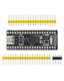
Szín: STM32F411 - STM32F401 STM32F411 Fejlesztőkártya V3.0 STM32F401CCU6 STM32F411CEU6 STM32F4 Oktatótábla 84Mhz 64KB RAM
723 Ft 1 247 Ft
STM32F401CCU6 3.0/STM32F411CEU6 3.0 Development Board
STM32F401CCU6 core board V3.0
Freq. 84Mhz ROM:256KB RAM:64KB
STM32F411CEU6 core board V3.0
Freq. 100MHZ ROM:512KB RAM:128KB
Core Board Information
Baidu network disk is not recommended to download data, domestic code cloud is fast
Gitee code cloud information link: https://gitee.com/WeAct-TC/MiniF4-STM32F4x1.git
Github information link: https://github.com/WeActTC/MiniF4-STM32F4x1.git
Baidu network disk link: https://pan.baidu.com/s/1vW9H-q9C5n2yVAEp38pw5A
Extract code: gxnx
STM32 download and burn part of the tutorial: https://www.weact-tc.cn/2019/11/30/STM32Download/
Part of MicroPython tutorial: https://www.weact-tc.cn/2020/01/01/micropython/
MicroPython compilation information: https://github.com/WeActTC/WeAct_F411CE.git
25MHZ high speed crystal oscillator & 32.768Khz 6PF low speed crystal oscillator
V3.0 version began to use lead-free process, the pin header is gold-plated pin header, more environmentally friendly
Flash pads have been reserved and USBDisk && FATFFS routines are provided
WeAct HID FW Bootloader has been burned out of the factory. It is a special factory test version, and hex is not provided.
Support MicroPython programming, provide available MicroPython firmware, see the link for configuration files, but do not provide technical answers!
Support Arduino programming, see Github https://github.com/stm32duino/Arduino_Core_STM32 for details
Boards with version V1.3 and above have 3 buttons, reset button, BOOT0 button, and user buttons.
How to enter ISP mode
Method 1: Press and hold the BOOT0 button and the reset button under the power-on state, then release the reset button, and release the BOOT0 button after 0.5 seconds
Method 2: Hold down the BOOT0 key when power is off, and release the BOOT0 key 0.5S after power on
DFU mode: just use the data cable to connect to the computer, if there is a problem of unrecognized, you can properly heat the chip (25 ° C), and then re-enter the ISP mode
Serial port mode: use USB to serial port to connect PA9 and PA10 of the core board
Software: STM32CubeProg.
WeAct HID FW Bootloader
No need for USB to serial port, no debugger, no computer driver, just a TYPE-C data cable to complete the firmware download
For details, see Code Cloud / Soft / WeAct HID FW Bootloader /
How to enter HID Bootloader after writing to APP
Press and hold the KEY button, click the reset button, LED C13 flashes, release the KEY button to enter
-
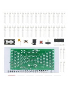
5V-os elektronikus homokóra barkácskészlet Vicces elektromos gyártási készletek, precíz LED-lámpákkal, kétrétegű PCB
270 Ft 465 FtThe suite adopts 1.6mm double layer PCB, and the circuit consists of 57 pieces warm white LED. Under the control of MCU program, it displays analog hourglass image. The micro switch can adjust the speed of hourglass, the bright LED quantity at the same time is 28, and it can be used as decoration of small night light. 0.5W power consumption. -
Szín: ST-LINK V2 - 1 DB ST LINK Stlink ST-Link V2 Mini STM8 STM32 szimulátor letöltési programozó programozás
396 Ft 683 FtNOTE:Its color is randomly!!!
1. support the full range of STM32 SWD debugging interface, a simple 4-wire interface (including power), fast, stable; interface definition housing directly marked! Do not need to read the manual;
2. support the full range of STM8 SWIM download debugging (common development environments such as IAR, STVD etc. are supported); supported software versions as follows:
① ST-LINK Utility 2.0 and 4.2.1 above
② STVD and above
③ STVP 3.2.3 and above
④ IAR EWARM V6.20 and above
⑤ IAR EWSTM8 V1.30 and above
⑥ KEIL RVMDK V4.21 and above
3. support for automatic firmware upgrades to ensure follow-up support ST products. The factory firmware has been upgraded to the latest V2.J17.S4;
4. increase the 5V power output, the output I / O ports are protected afraid of operational errors caused by ST-LINK V2 damage!
5. the interface easy to use copper gilded horns seat pitch of 2.54, with 20CM DuPont line, the line can respond to different target sequence, flexible wiring;
6. the use of U disk aluminum housing protects the motherboard, easy to carry, is not afraid of static electricity, afraid to fall throw touch.
7.with data package, containing: (e-file, disk, and network support Baidu QQ mailbox to send)
1, STLINK / V2 driver;
2, KEIL MDK (4.60) development environment (and other common development environments)
3, IAR STM8 (1401) development environment (and other common development environments)
4, STVD STM8 development environment (and other common development environments)
5, a number of classic STM32 information (including a large number of source code examples and video tutorials)
6, a number of classic STM8 information (including a large number of source code examples and learning experience) -
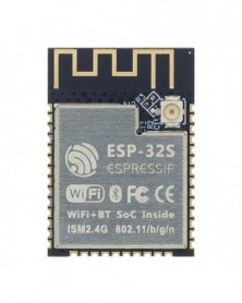
Szín: ESP-32S - ESP-32S ESP-WROOM-32 ESP-WROOM-32D ESP32 ESP-32 Bluetooth és WIFI kétmagos CPU alacsony fogyasztású MCU ESP
289 Ft 498 FtESP32 is a complete,small form factor(SFF)802.11 b/g/n/e/i(2.4GHz)WLAN plus BT4.2combo solution optimized for low-power,mobile consumer electronics,wearable andInternet of Things(IOT) devices.ESP32 integrates all WLAN and BT functionalityin a single package to support a low cost,layout-friendly implementation whileallowing flexibility for platform specific customization.
ESP32 is a highly integrated solution withless than 10 external components.
ESp32 integrates the transmit /receive RFfunctionality including the antenna swiches,RF balun,power amplifier,low noisereceive amplifier,filters,power management,and advanced calibratiom ciacuitriesthat allow the solution to dynamically adjust itself to adapt to externalcircuit implefections.
The entire solution reduces Printed CircuitBoard (PCB) area,time-to-market,and bill-of-material(BOM)costs while addingcapablities and processing power.the mass production of ESP32 does not requireexpensive and specialized Wi-Fi test equipment.
ESP32's uitra low power consumption radioarchiteature and proprietary power save technologies extend batter life inreal-world applications,using the following features:
Fine granularity clock-gating
Multiple low-power modes,and
Dynamic voltage scaling
For instance,in a low-power IoT sensor hubapplication scenario,ESP32 is woken up periodically and only when a specifiedcondition is detected;low duty cycle is used to minimize the amount of energythat the chip expends.The output power of the power amplifier can also beadjusted,so that an optimal trade off between the communication range,data rateand power consumption is achieved. -
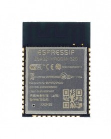
Szín: ESP-WROOM-32 - ESP-32S ESP-WROOM-32 ESP-WROOM-32D ESP32 ESP-32 Bluetooth és WIFI kétmagos CPU alacsony fogyasztású
289 Ft 498 FtESP32 is a complete,small form factor(SFF)802.11 b/g/n/e/i(2.4GHz)WLAN plus BT4.2combo solution optimized for low-power,mobile consumer electronics,wearable andInternet of Things(IOT) devices.ESP32 integrates all WLAN and BT functionalityin a single package to support a low cost,layout-friendly implementation whileallowing flexibility for platform specific customization.
ESP32 is a highly integrated solution withless than 10 external components.
ESp32 integrates the transmit /receive RFfunctionality including the antenna swiches,RF balun,power amplifier,low noisereceive amplifier,filters,power management,and advanced calibratiom ciacuitriesthat allow the solution to dynamically adjust itself to adapt to externalcircuit implefections.
The entire solution reduces Printed CircuitBoard (PCB) area,time-to-market,and bill-of-material(BOM)costs while addingcapablities and processing power.the mass production of ESP32 does not requireexpensive and specialized Wi-Fi test equipment.
ESP32's uitra low power consumption radioarchiteature and proprietary power save technologies extend batter life inreal-world applications,using the following features:
Fine granularity clock-gating
Multiple low-power modes,and
Dynamic voltage scaling
For instance,in a low-power IoT sensor hubapplication scenario,ESP32 is woken up periodically and only when a specifiedcondition is detected;low duty cycle is used to minimize the amount of energythat the chip expends.The output power of the power amplifier can also beadjusted,so that an optimal trade off between the communication range,data rateand power consumption is achieved. -
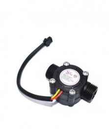
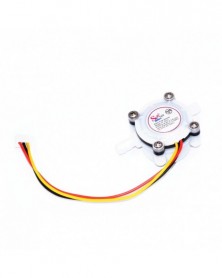
Szín: YF-S201 - 1 db Vízáramlás érzékelő áramlásmérő Hall áramlásérzékelő Vízszabályozás 1-30L/min 2.0MPa YF
361 Ft 622 Ft12V Water Flow Sensor DC 5-18V Flowmeter Hall Flow Sensor Water Control Liquid Flow Sensor Switch 1-30L/min 2.0MPa YF-S201
Description:
External threads: 1/2"
temperature: -25~ 80
Allowing pressure: pressure 1.75Mpa
Operating humidity range: 35% ~90% RH (no frost)
Use temperature: 80
Load capacity: 10 mA (DC 5V)
Working voltage range: DC 5~18 v
Maximum operating current: 15 mA (DC 5V)
The lowest rated working voltage: DC 4.5 5V-24V
Size : 6x4cm
Color : Black
Package Included:
1 x Water Flower Sensor -
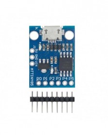
Szín: Digispark-Blue - 1 DB/LOT GY Digispark Kickstarter miniatűr minimális fejlesztőkártya TINY85 modul USB
345 Ft 594 FtThe Specs:
1. Support for the Arduino IDE 1.0 (OSX/Windows/Linux).
2. Power via USB or External Source or 7-16 v to 5 v (automatic selection).
3. The On - board, 150 ma 5 v Regulator.
4. Built - in USB and serial was debugging).
5. 6 I/O Pins (2 are informs the for USB only if your program actively communicates over USB, otherwise you can use all 6 even if you are programming via USB).
6. 8 k Flash Memory (about 6 k after bootloader).
7. The I2C and SPI (vis USI).
8. PWM on 3 pins (more possible with Software PWM).
9. The ADC on 4 pins.
10. The Power LED and the Test/Status leds. -
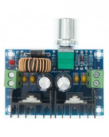
XH-M401 DC-DC Step Down Buck átalakító tápegység modul XL4016E1 PWM Állítható 4-40V 1,25-36V Step Down Board 8A 200W
396 Ft 682 FtSpecification: Product name: DC step-down module Converter Voltage regulating mode: PWM modulation Input voltage: DC4-40V Output voltage: DC1.25-36V Max output current: 8A (more than 5A for long time use,need Fan if over 5A) Max power: 200W Conversion efficiency: 94% Switching frequency: 180KHZ Dimensions: 61*41*27mm Chip: switching regulator Regulating chip XL4016 with Over current protection, Over temperature protection,Short circuit protection When reach maximum output current 8A, need to add fan. Long term work recommended about 5A Panel Mounting: 1. Drill holes in the Panel 7mm 2. Extended potentiometer handle 3. Lock screw sleeve upper knob -
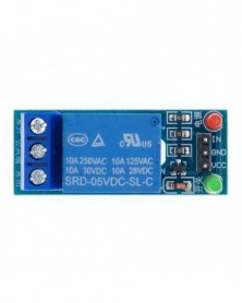
Szín: 1 relé modul - 1 2 4 8 csatornás 5 V-os relémodul Alacsony szint az SCM háztartási készülékek vezérléséhez
179 Ft 309 FtRelay contact capacity 250V10A. Relay output normally open, normally closed;
• active low. 5V relay signal input voltage range :0-5V;
• VCC system power. JD-VCC relay power. Default 5V relay. JD-VCC and VCC shorted
-
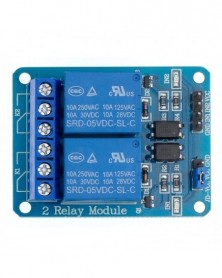
Szín: 2 relé modul - 1 2 4 8 csatornás 5V-os relémodul Alacsony szint az SCM háztartási készülékek vezérléséhez
235 Ft 406 FtRelay contact capacity 250V10A. Relay output normally open, normally closed;
• active low. 5V relay signal input voltage range :0-5V;
• VCC system power. JD-VCC relay power. Default 5V relay. JD-VCC and VCC shorted
-
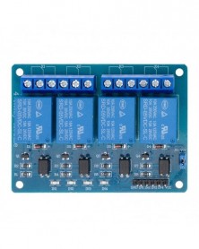
Szín: 4 relé modul - 1 2 4 8 csatornás 5 V-os relémodul Alacsony szint az SCM háztartási készülékek vezérléséhez
339 Ft 584 FtRelay contact capacity 250V10A. Relay output normally open, normally closed;
• active low. 5V relay signal input voltage range :0-5V;
• VCC system power. JD-VCC relay power. Default 5V relay. JD-VCC and VCC shorted
-
Szín: 8 relé modul - 1 2 4 8 csatornás 5 V-os relémodul Alacsony szint az SCM háztartási készülékek vezérléséhez
568 Ft 980 FtRelay contact capacity 250V10A. Relay output normally open, normally closed;
• active low. 5V relay signal input voltage range :0-5V;
• VCC system power. JD-VCC relay power. Default 5V relay. JD-VCC and VCC shorted
-
10 DB/LOT W25Q32 W25Q32B 25q32 W25Q32BVSIG 25Q32BVSIG W25Q32BVSSIG
303 Ft 523 FtNotice: The new tracking number for China Post Ordinary Small Packet Plus can be traced only befor it arrive the airport of your country,please choose China Post Air Mail if you want a full tracking info.
Tracking info of China Post Ordinary Small Packet Plus can be check here: www.17track.net/en -
D41 1db víz kávé áramlásérzékelő kapcsoló mérő áramlásmérő számláló 0,3-6L/perc belső átmérő 2mm YF-S401
363 Ft 626 FtNotice: The new tracking number for China Post Ordinary Small Packet Plus can be traced only befor it arrive the airport of your country,please choose China Post Air Mail if you want a full tracking info.
Tracking info of China Post Ordinary Small Packet Plus can be check here: www.17track.net/en
Description:
External threads: 1/2"
temperature: -25~ 80 centigrade
Allowing pressure: pressure 1.75Mpa
Operating humidity range: 35% ~90% RH (no frost)
Use temperature: ≤ 80centigrade
Load capacity: ≤ 10 mA (DC 5V)
Working voltage range: DC 5~18 v
Maximum operating current: 15 mA (DC 5V)
The lowest rated working voltage: DC4.5 5V-24V
Quantity:1PC
Size : 5.7cmX4cm/2.24''X1.57''
Color : white
Lead way:
Red IN connect the anode
Yellow OUT signal output line
Black GND connect the cathode -
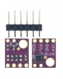
Szín: SHT31 - 1 DB SHT31 hőmérséklet SHT31-D páratartalom érzékelő modul mikrokontroller IIC I2C Breakout Weather 3V 5V
329 Ft 568 FtDescription:
Sensiron Temperature/Humidity sensors are some of the finest & highest-accuracy devices you can get. And, finally we have some that have a true I2C interface for easy reading. The SHT31-D sensor has an excellent ±2% relative humidity and ±0.3°C accuracy for most uses.
Unlike earlier SHT sensors, this sensor has a true I2C interface, and (bonus!) even with two address options. It also is 3V or 5V compliant, so you can power and communicate with it using just about any microcontroller or microcomputer.
Such a lovely chip - so we spun up a breakout board with the SHT31-D and some supporting circuitry such as pullup resistors and capacitors. Each order comes with one fully assembled and tested PCB breakout and a small piece of header. You'll need to solder the header onto the PCB but it's fairly easy and takes only a few minutes even for a beginner.
Power Pins:
Vin - this is the power pin. The chip can use 2.5-5VDC for power. To power the board, give it the same power as the logic level of your microcontroller - e.g. for a 5V micro like for Arduino, use 5V. For a 3.3V controller like a Raspbery Pi, connect to 3.3V
GND - common ground for power and logic
I2C Logic pins:
SCL - I2C clock pin, connect to your microcontrollers I2C clock line. This pin has a 10K pullup resistor to Vin
SDA - I2C data pin, connect to your microcontrollers I2C data line. This pin has a 10K pullup resistor to Vin
Other Pins:
ADR - This is the I2C address selection pin. This pin has a 10K pull down resistor to make the default I2C address 0x44. You can tie this pin to Vin to make the address 0x45
RST - Hardware reset pint. Has a 10K pullup on it to make the chip active by default. Connect to ground to do a hardware reset!
ALR - Alert/Interrupt output. You can set up the sensor to alert you when an event has occured. Check the datasheet for how you can set up the alerts
Package Included:
1 X Sensiron SHT31-D Temperature Humidity Sensor -
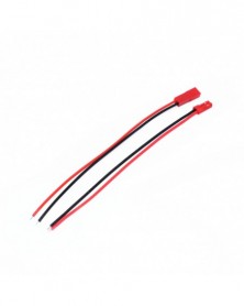
Szín: 1 szett - ISD1820 felvevő modul hangmodul a hangkártya telefonmodul kártya mikrofonokkal hangszóró
267 Ft 461 FtISD1820 recording module voice module the voice board telediphone module board with Microphones Loudspeaker
Feature:
With looping, jog playback, single-pass play function
Available single-chip control
This module can directly drive a small speaker 8 ohm 0.5W
Working voltage: DC 3 to 5V
Loudspeaker: 8Ω, 0.5W
Power supply: 3 - 5V
Size: 3.7 x 4.1cm / 1.45 x 1.61 inch
Package included:
1 x SD1820 Sound Voice Module with speaker
the main chip: ISD1820
size: 38mm * 42.5mm
the working voltage: DC 3 ~ 5V
Loudspeaker: 8Omega, 0.5W.
features:
1.An easy to use 10 seconds of voice recording
2.high-quality, natural voice restored
3.can be used as propaganda module
4.with looping, jog playback, single-pass play function
5.available single-chip control
6.this module can directly drive a small speaker 8 ohm 0.5W
Power supply :3-5V, which can be accessed pin power;
Audio recording control mode: the key to control or microcontroller, IO has drawn the line of control;
Buttons control audio recording method of operation:
REC button: record button, you can press and hold the recording, release the button to stop recording;
RLAYE key: trigger mode playback, press will play this whole speech;
PLAYL key: jog mode playback, press and hold until playback, release to stop playback;
RPL Jumper: loop mode control, loop playback;
FT Jumper: direct control, microphone voice through the speaker can playback;
Shipping Included:
1PCS x ISD1820 Module
1PCS x Loudspeaker
1PCS x Free cables.