- -52%

Szín: kék - RF teljesítményerősítő kártya adó-vevő áramkör PCB walkie-talkie készlet erősítő kártya
Szín: kék - RF teljesítményerősítő kártya adó-vevő áramkör PCB walkie-talkie készlet erősítő kártya
1 630 Ft
52% megtakarítás
3 395 Ft
Nincs adó
-2
/
 2
A Megtakarítás az Üzletben is Beváltható
2
A Megtakarítás az Üzletben is Beváltható
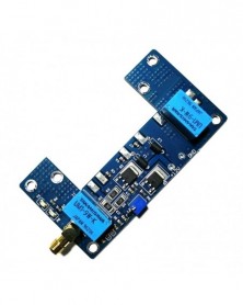
The amplifier can uses RA,M Toshiba SU series module and the panel has auto transceiver circuit(not includ the module and radiator).
The module power voltage has an effect on the transmitting power.Within the working voltage,the lower the voltage,the lower the transmitting power.
The antenna affects the communication distance and please select the right antenna.
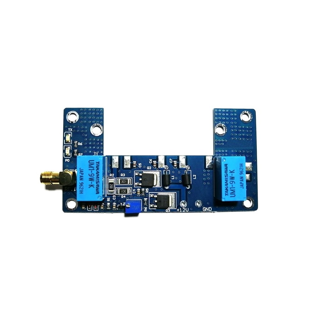
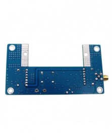
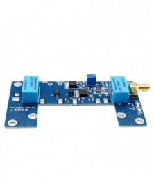
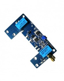
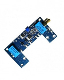
RF power amplifier board:The PCB panel is peripheral circuit for power module.It can work normally with RA,M series,Toshiba SU series module.It is for 1-5W handheld walkie-talkie.Auto ransceiver circuit,increasing the transmitting power.
1:LED indicator light(green);transmissing LED indicator light(red)
2:1-5W power input(external screw inner hole SMA)
3:DC-12-13.8V power supply interface
4:Module the second pin (VGG) voltage & power adjusting,clockwise knobing,the voltage increases;Anti-clockwise knobing,the voltage decreases.
5:Power output interface(the upper negative,lower positive)
Specification:
The max affordable power:70W
Input power:1-5W
Transmitting frequency:depends on the module mode
Output power:depends on the install module mode
Power supply:DC 10-13.8V
Standby current:10-20mA
Output power:10-80W(vary with module)
Working frequency:130-170,400-470(vary with module)
Insertion loss:-1.5DB
Standing Wave Ratio: 1.5
Colour:blue
Material:plastic
Size:94 x 50 x 1.6mm
Package Contents:
1 * RF Amplifier Board Transceiver Circuit PCB
Only the above package content, other products are not included.
Note: Light shooting and different displays may cause the color of the item in the picture a little different from the real thing. The measurement allowed error is /- 1-3cm.
The module power voltage has an effect on the transmitting power.Within the working voltage,the lower the voltage,the lower the transmitting power.
The antenna affects the communication distance and please select the right antenna.
RF power amplifier board:The PCB panel is peripheral circuit for power module.It can work normally with RA,M series,Toshiba SU series module.It is for 1-5W handheld walkie-talkie.Auto ransceiver circuit,increasing the transmitting power.
1:LED indicator light(green);transmissing LED indicator light(red)
2:1-5W power input(external screw inner hole SMA)
3:DC-12-13.8V power supply interface
4:Module the second pin (VGG) voltage & power adjusting,clockwise knobing,the voltage increases;Anti-clockwise knobing,the voltage decreases.
5:Power output interface(the upper negative,lower positive)
Specification:
The max affordable power:70W
Input power:1-5W
Transmitting frequency:depends on the module mode
Output power:depends on the install module mode
Power supply:DC 10-13.8V
Standby current:10-20mA
Output power:10-80W(vary with module)
Working frequency:130-170,400-470(vary with module)
Insertion loss:-1.5DB
Standing Wave Ratio: 1.5
Colour:blue
Material:plastic
Size:94 x 50 x 1.6mm
Package Contents:
1 * RF Amplifier Board Transceiver Circuit PCB
Only the above package content, other products are not included.
Note: Light shooting and different displays may cause the color of the item in the picture a little different from the real thing. The measurement allowed error is /- 1-3cm.

Szállításii feltételek

Biztonsági feltételek

Visszaküldési feltételek