Kereskedelmi, irodai és ipari
-
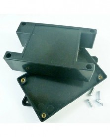
Fekete műanyag ház ABS anyagú héj csatlakozódoboz RS485 RS232 Wifi relé motorvezérlő elektronikus modulokhoz
396 Ft 809 Ft
Product Name:
White Plastic case ABS Material Junction Box for RS485 RS232 Wifi Bluetooth Relay
Package inlcuded:
1 x ABS Black
Plastic shell
Description:
Material : ABS
Size : 96.5*49.8*31.5mm
Weight : 33g
Typical applications:
for
Bluetooth Relays
for RS485 Relay:
for RS232 Relay
-
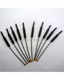
10 db Mini Phillips csavarhúzó 2,0 mm
373 Ft 761 FtProduct Name: 10 pcs Mini Phillips screwdriver 2.0mm
Packing list:
10 PCS Mini Phillips screwdriver 2.0mm
Description:
Mini screwdriver:
Specifications: 2.0MM, Phillips screwdriver 2.0mm
Handle material: environmentally friendly PVC
Total length of handle: 13MM
Tool holder length: 35MM
Net weight: 2.8 grams.
-
2.4Ghz 20dBm vezeték nélküli RF soros UART modul 5V 3V AT parancs cserélje ki a CC1101 SI4432
553 Ft 1 128 FtProduct Name: 20dBm RS232 (TTL Level) Wireless Transceiver Module TTL232 Serial ports 2.4G RF Board 5V 3V replace CC1101 CC2500 SI4432 SI4463
Packing list:
1 pcs 2.4G 20dBm RS232(TTL Lever) Wireless Transceiver Module
Overview:
TB387 is based on 2.4GHz frequency band wireless transparent data-transmission module.
This Module supports most basic AT commands: baud rate, ID number, frequency settings and inquiries; factory settings; version information.
When the module is in AT module, users can use serial-port to issue AT commands to set the module's parameters.
When the module is in transparent data transfer mode, the user transmit data, frame number data module, add packaged rowcount, and then automatically transmit , at reliable range, the module will automatically re-transmit data to ensure successful transmission.
Performance Parameter:
Working voltage: 3.3V-5.5V;
RS232 Interface ( 3.3V/5V TTL level)
Frequency range: 2402~2482MHz
Transmit power: 20dBm(100mw);
Receiver sensitivity: -87dBm;
Operating temperature: -40~ 85 ° c;
Transparent transmission mode baud rate:
2400,4800,9600(Default),14400,19200,38400,57600,115200,12800,25600
AT mode configured baud rate fix is: 9600;
Open ground Transmission distance : 400M
Pinout :
1, VDD:3.3V or 5V power supply ;
2, GND: Power Ground;
3, TXD: serial port output, MCU or USB to serial port RXD;
4, RXD: serial port input, MCU or USB to serial port TXD;
5, CMD: Enter PIN AT mode, active low level;
AT Commands Data Sheet : Please contact seller on message ;
Typical applications:
2402-2482MHz ISM/SRD band systems
for Arduiuo UNO MEGA2560 DUE MCU
Consumer electronics
Access control, Attendance, Logistics
Smart Furniture
Robert
Wireless sensor
Smart Home
Application example:
Wireless communication between UNO and PC(Also application with other 3.3V/5V level MCU ,for example: Raspberry pi FPGA CPLD STM32 C8051 PIC AVR MSP430)
for this Applications you also need:
1: USB to ttl cable; Click here
2: UNO/MEGA2560/DUE
ARDUIUO IDE Serial data Transceiver:
Copy the following code:
//----------------------------------------------------------------------//
// Pin 13 has an LED connected on most ARDUIUO boards.
int led = 13;
String comdata = "";
void setup()
{
// initialize the digital pin as an output.
pinMode(led, OUTPUT);
Serial.begin(9600);
Serial.println("Hello, I am Arduiuo!");
}
//Serial data transceiver
void loop()
{
while (Serial.available() > 0)
{
digitalWrite(led, HIGH); // turn the LED on (HIGH is the voltage level)
comdata = char(Serial.read());
delay(2);
}
if (comdata.length() > 0)
{
Serial.println(comdata);
comdata = "";
}
digitalWrite(led, LOW); // turn the LED off by making the voltage LOW
}
//----------------------------------------------------------------------// -
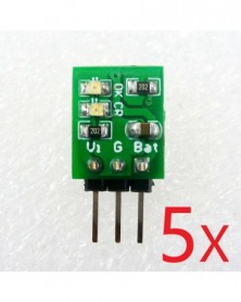
C típusú USB mini párásító barkácskészletek Mist Maker illesztőprogram áramkör Fogger porlasztó film porlasztó lap
227 Ft 463 Ft
Product Name: Type-C USB Mini Humidifier DIY Kits Mist Maker Driver Circuit Board Fogger Atomization Film Atomizer Sheet Mini Oscillating
Package inlcuded:
1x TYPE-C Atomizer / humidifier controller
1x Atomizing sheet
1x Humidifier cotton rod
Description:
Working voltage: DC 3.7-5.5V (recommended 5V)
Work current: 330mA
Stand-up current: 21uA
Power supply interface: Type-C USB
Humidifier interface: pH2.0 terminal
Frequency: 108kHz
Multiple function modes: Uninterrupted work/Intermittent work/Timing work
Size: 40 x 16.5 x 9 mm
Weight: 4.5 g
Application
Smart home, home automation
Household atomizer/humidifier
Electronic DIY
Small USB device
Choose different function modes by welding the M2, M1, M0 ports
Wiring diagram:
-
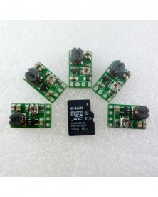
5 db mini 5V 1A 18650 lítium akkumulátor töltőkártya töltő modul ME4056 cserélje ki a TP4056
480 Ft 980 FtProduct Name: 5PCS mini 5V 1A 18650 Lithium Battery Charging Board Charger Module ME4056 replace TP4056
Packing list:
5 PCS DD08CRMA Mini Li Lithium Battery Charger Module
Description:
Mini Lithium Battery Charger Module - Linear charging.
Input voltage : DC 4.5V-8V(Recommend DC 5V)
Maximum charging current : 1000MA
Full charge voltage : 4.2V -2% .
Led indicator : "OK" LED is fully charged OR battery failure status indicator;
"CR" LED is charge status indicator
Operating ambient temperature : -40° to 85°
Storage temperature : -65° to 125°
Except pin size : 12.3mm*10mm*4mm( very small!!!)
Weight : 0.7g( Very light!!!)
2.54MM pin can be inserted directly into the breadboard
Can be used DC 5-6V power supply charger(Such as Solar panels)Charging module comes with charge-management functions, will not overcharge or over discharge
Comes with rechargeable function,Will enter standby mode when fully charged.When the battery capacity is below 80% , the charging start.
Applications:
Battery powered equipment
LI Lithium Battery 18650
Mobile phone
Solar charging
MP3/MP4 player
Audio equipment
Portable Devices
Bluetooth Applications
-
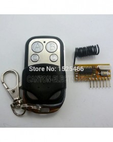
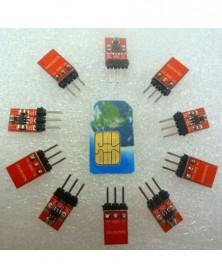
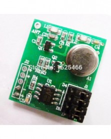
433Mhz UNO vezeték nélküli dekódoló készlet 5V RF távirányító EV1527 távirányító Arduino Mega2560 DUE-hoz
514 Ft 1 048 FtTypical applications:
Remote control switch
Smart Home / Home Automation
Diy UNO MEGA2560 Remote Control
RC switch
Product Name : UNO Wireless Decoding Kit 4CH RF Remote Control Switch EV1527 Keyfob for Arduiuo Mega2560 DUE
Package inlcuded (Does not include Arduiuo UNO)
1 pcs 433M 1527/2262 Superheterodyne Receiver decoder module;
1 pcs 433M EV1527 transmitter remote (This remote doesnot have a battery(12V 27A) , Please buy in your local market ) .
Arduiuo uno/mega2560 Code :
//*******************************************//
//Author: cantone-electonics
//More information welcome to : www.canton-electronics.com
//Arduiuo 1.0.4
//uno R3
//uno 4 channel EV1527/PT2262 Decoding module
int VCC = 13;//as power vcc
int D3 = 12;
int D2 = 11;
int D1 = 10;
int D0 = 9;
int VT = 8;
int Relay1 = A0;
int Relay2 = A1;
int Relay3 = A2;
int Relay4 = A3;
int InputState = 1; //variable for reading the input status
// the setup routine runs once when you press reset:
void setup() {
// initialize the digital pin
pinMode(VCC, OUTPUT);
pinMode(D3, INPUT);
pinMode(D2, INPUT);
pinMode(D1, INPUT);
pinMode(D0, INPUT);
pinMode(VT, INPUT);
digitalWrite(VCC, HIGH);//AS VCC
/*
//Activate input pin internal pull-up resistors
digitalWrite(I0, HIGH);
digitalWrite(I1, HIGH);
digitalWrite(I2, HIGH);
digitalWrite(I3, HIGH);
digitalWrite(VT, HIGH);
*/
Serial.begin(9600);
delay(2000);//Waiting for rf receiver module startup
}
// the loop routine runs over and over again forever:
void loop() {
InputState = digitalRead(VT);
if(InputState)
{
Serial.print("D3 D2 D1 D0 VT \n");
InputState = digitalRead(D3);
if(InputState) Serial.print("1 ");else Serial.print("0 ");
InputState = digitalRead(D2);
if(InputState) Serial.print("1 ");else Serial.print("0 ");
InputState = digitalRead(D1);
if(InputState) Serial.print("1 ");else Serial.print("0 ");
InputState = digitalRead(D0);
if(InputState) Serial.print("1 ");else Serial.print("0 ");
Serial.print("1\n");
}
do{
InputState = digitalRead(VT);
}while(InputState);
}
//*******************************************//
Description:
433M 1527/2262 Superheterodyne Receiver decoder module, click here;
433M EV1527 transmitter remote, click here.
transmitter remote Power supply : 12V 27A battery . (This remote doesnot have a battery , Please buy in your local market )
Can directly insert Arduiuo UNO/MEGA2560/DUE(also can use other MCU:ARM FPGA/CPLD PIC AVR Etc. )
-
10db 2400-2500MHz Ipex interfész 2.4G antenna Arduino Spark Core ESP8266 Wifi Zigbee CC2500 NRF24L01 RF vezeték nélküli
598 Ft 1 221 FtProduct Name:10pcs 2400-2500MHz Ipex Interface 2.4G Antenna for Arduiuo Spark Core ESP8266 Wifi Zigbee CC2500 NRF24L01 RF Wireless Module
Packing list:
10 pcs 2400-2500MHz ISM Band Ipex Antenna
Description:
Electrical Characteristics:
Frequency 2400 ~ 2500 MHz
S.W.R. <= 2.0
Antenna Gain 2.0 ± 0.7dBi @ 2450MHz
Polarization Linear
Impedance 50 Ohm
Material & Mechanical Characteristics:
Material of Radiator Cu
Cable Type 1.13
Connector Type Ipex Connector
Connector Pull Test >= 1 Kg
Length : About 10cm
Weight : About 1.1g(Very light)
Environmental:
Operation Temperature - 40 °C ~ 65 °C
Storage Temperature - 40 °C ~ 80 °C
Typical applications:
IEEE 802.11 b/g/n WLAN System
Wireless Communication System
WiFi / WiMAX / MIMO System
Bluetooth : CC2540
Zigbee : CC2530
WIFI Module : ESP8266,Spark Core
2.4G RF UART Module: CC2500 Nrf24l01
Smart Home / Home Automation -
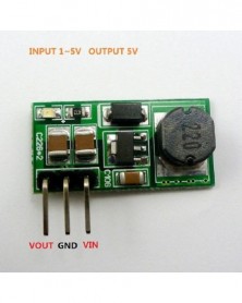
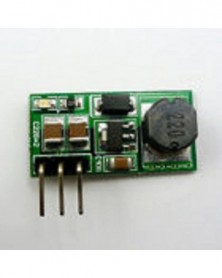
DC-DC 1-5V – 5V Step up Boost Converter Module az Arduino Pro mini Breadboardhoz
247 Ft 505 FtBelow item is powered by Canton-electronics Ltd .
Product Name: DC-DC 1-5V to 5V Step up Boost Converter Module for Ardiuno Pro mini Breadboard
Module No.: TB294
Packing list:
1 PCS 1V-5V TO 5V Step-up Modules
Description:
Input voltage 0.8 ~ 5V, output 5V
Maximum output current: 600MA
Start Voltage 0.8V, Output Current 30MA
INPUT 1-1.5V, OUTPUT 5V 40-80MA;
INPUT 1.5-3V, OUTPUT 5V 80-300MA;
INPUT 3-4.2V, OUTPUT 5V 300-400MA;
INPUT above 4.2V, OUTPUT 5V 400-600MA;
DC-DC Boost module working frequency 100KHZ. efficiency is normal 80% , can be up to 95% . On-board high-precision,
Size : 20mm X 12mm (length X width)
Pin spacing is 2.54mm,Directly into the breadboard for power supply Ardiuno MCU ARM FPGA CPLD
The input and output terminals using the wire bonding connection, the selection of a plurality of parallel filtering of tantalum capacitors, effectively filter out the power supply noise.
Overcurrent burn out warranty!
Booster plate, regulator, the output voltage is always 5V!
Applications
Battery powered equipment
Breadboard Power Supply
Ardiuno UNO MEGA2560 DUE Power Supply
Camera, Video camera
VCR
PDA
LED Lighting
Wireless communication equipment
MP3/MP4 player
Audio equipment
This is a DC-DC voltage converter module,Must be noted when using:
1 Input voltage can not be greater than the maximum input range
2 Output power can not be greater than the maximum load for a long time
3 Input power must be greater than the output power, because the power consumption of the module itself
-
Adjon meg UNO MEGA2560 kódot, 64x16 pontos mátrix LED-et az Arduino AVR MCU diy karácsonyi ajándékokhoz.
2 353 Ft 4 803 FtProduct Name: Provide uno mega2560 code 64x16 dot Matrix LED for diy Sign Light Neon Bright UNO MCU
Module No.: TB275
With the display you get full documentantion and example sketch by email! Packing list does not include Arduiuo UNO!
Packing list(Does not include Arduiuo UNO) :
1 PCS 64 x16 Red Pixel Matrix LED
1 PCS UNO/MEGA2560 adapter board
1 pcs adapter cable
Description :
F3.75 RED Color 64 X 16 matrix displays
Red pixels
Driver IC : 74HC245 74HC595 74HC138 74HC04 APM4953
Can display variety of patterns and characters
Provided arduiuo UNO MEGA2560 code
Size: 304MM x 76MM
Weight: About 240g
Use:
USE for Arduiuo UNO R3:
You can use this software,m ake your favorite patterns:
Display effect:
-
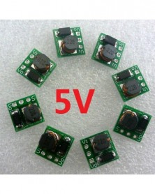
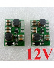
DC-DC 1,5 V 3 V 3,3 V 3,7 V 4,5 V 5 V – 6 V Fokozatos, fokozó átalakító modul relé motor
247 Ft 505 FtBelow item is powered by Canton-electronics Ltd .
Product Name: DC-DC 1.5V 3V 3.3V 3.7V 4.5V 5V to 6V Step-up Boost Converter Module for Relay Motor
Module No.: TB396
Packing list:
1 PCS 1V-6V TO 6V Step-up Boost Modules(PCB Color : RED)
Description:
Input voltage 0.8 ~ 6V, output 6V
Maximum output current: 600MA
Start Voltage 0.8V, Output Current 20MA
INPUT 1-1.5V, OUTPUT 6V 20-60MA;
INPUT 1.5-3V, OUTPUT 6V 60-200MA;
INPUT 3-4.2V, OUTPUT 6V 200-300MA;
INPUT 4.2-5V, OUTPUT 6V 300-500MA;
INPUT above 5V, OUTPUT 6V 500-600MA;
DC-DC Boost module working frequency 100KHZ. efficiency is normal 80% , can be up to 95% . On-board high-precision,
Size : 20mm X 12mm (length X width)
The input and output terminals using the wire bonding connection, the selection of a plurality of parallel filtering of tantalum capacitors, effectively filter out the power supply noise.
Overcurrent burn out warranty!
Booster plate, regulator, the output voltage is always 6V!
Prompt : The new version is red PCB,Component layout has changed, Pin order and parameters unchanged.
Applications
Battery powered equipment
Breadboard Power Supply
6V Small power motors
Camera, Video camera
6V Toy car
PDA
LED Lighting
Wireless communication equipment
Ardiuno UNO MEGA2560 PRO MINI power supply
Audio equipment
This is a DC-DC voltage converter module,Must be noted when using:
1 Input voltage can not be greater than the maximum input range
2 Output power can not be greater than the maximum load for a long time
3 Input power must be greater than the output power, because the power consumption of the module itself
Input 3.7V/480MA,Output 6V/250MA
Input 4.5V/600MA,Output 6V/380MA
Input 5V/700MA,Output 6V/500MA
-
Szín: 4V2 X2 164MA - 1-4 cellás 3,7 V Li-ion polimer 3,2 V LiFePO4 lítium akkumulátorcsomagok Charge Balance BMS
330 Ft 674 FtProduct Name: 1-4 cell 3.7V Li-ion Polymer 3.2V LiFePO4 lithium Battery packs Charge Balance BMS Charger protection board for 18650 14500
Packing list:
1 PCS Multi-cell Cell Li-ion/Polymer/LiFePO4 Battery Charge Balance Module
Description:
4.2V(4V2) version:
Multi-cell 3.7V/4.2V Li-ion/Polymer Battery(packs) Charge Balance Module
(1) High Precision Voltage Detection Circuit
Overcharge detection voltage 4.000~4.500V Accuracy±25mV
Overcharge release voltage 3.800~4.500V Accuracy±35mV
Standby detection voltage 2.70V Accuracy±15%
Standby release voltage 2.70V Accuracy±15%
(2) Delay times are generated by an internal circuit (external capacitors are unnecessary).
(3) Low consumption current
Operation mode Typ. value 2.5μA, max. value: 3.5μA (VDD=3.9V)
Standby mode Max. value:0.5μA (VDD=2.7V)
(4)Wide operation temperature range: -40℃~ 85℃
Main control chip : HY2213-BB3A
Size : 30mm x 28mm x 8mm
Weight : 3.5g
3.6V(3V6) version:
Multi-cell 3.2V/3.6V LiFePO4 Battery(packs) Charge Balance Module
(1) High Precision Voltage Detection Circuit
Overcharge detection voltage 3.200~4.000V Accuracy±25mV
Overcharge release voltage 3.000~4.000V Accuracy±35mV
Standby detection voltage 2.70V Accuracy±15%
Standby release voltage 2.70V Accuracy±15%
(2) Delay times are generated by an internal circuit (external capacitors are unnecessary).
(3) Low consumption current
Operation mode Typ. value 2.5μA, max. value: 3.5μA (VDD=3.2V)
Standby mode Max. value:0.5μA (VDD=2.0V)
(4) Wide operation temperature range: -40℃~ 85℃
Main control chip : HY2212-BB3A
Size : 30mm x 28mm x 8mm
Weight : 3.5g
Please contact me for the chip manual.
The value of Rb is the value of 4 resistors connected in parallel.
The Balance current is determined by the value of the Rb1- Rb4 resistor. Changing the value of Rb1- Rb4 can change the Balance current
4.2V(4V2) version : Balance current(A)= 4.2/Rb
3.6V(3V6) version : Balance current(A)= 3.6/Rb
A single module can be used for a maximum of 4 batteries (battery packs), using 2 or more modules in series, and can be used for 5-40 batteries (battery packs) in series. -
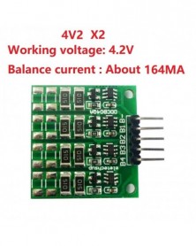
Szín: 4V2 X4 328MA - 1-4 cellás 3,7 V Li-ion polimer 3,2 V LiFePO4 lítium akkumulátorcsomagok Charge Balance BMS
330 Ft 674 FtProduct Name: 1-4 cell 3.7V Li-ion Polymer 3.2V LiFePO4 lithium Battery packs Charge Balance BMS Charger protection board for 18650 14500
Packing list:
1 PCS Multi-cell Cell Li-ion/Polymer/LiFePO4 Battery Charge Balance Module
Description:
4.2V(4V2) version:
Multi-cell 3.7V/4.2V Li-ion/Polymer Battery(packs) Charge Balance Module
(1) High Precision Voltage Detection Circuit
Overcharge detection voltage 4.000~4.500V Accuracy±25mV
Overcharge release voltage 3.800~4.500V Accuracy±35mV
Standby detection voltage 2.70V Accuracy±15%
Standby release voltage 2.70V Accuracy±15%
(2) Delay times are generated by an internal circuit (external capacitors are unnecessary).
(3) Low consumption current
Operation mode Typ. value 2.5μA, max. value: 3.5μA (VDD=3.9V)
Standby mode Max. value:0.5μA (VDD=2.7V)
(4)Wide operation temperature range: -40℃~ 85℃
Main control chip : HY2213-BB3A
Size : 30mm x 28mm x 8mm
Weight : 3.5g
3.6V(3V6) version:
Multi-cell 3.2V/3.6V LiFePO4 Battery(packs) Charge Balance Module
(1) High Precision Voltage Detection Circuit
Overcharge detection voltage 3.200~4.000V Accuracy±25mV
Overcharge release voltage 3.000~4.000V Accuracy±35mV
Standby detection voltage 2.70V Accuracy±15%
Standby release voltage 2.70V Accuracy±15%
(2) Delay times are generated by an internal circuit (external capacitors are unnecessary).
(3) Low consumption current
Operation mode Typ. value 2.5μA, max. value: 3.5μA (VDD=3.2V)
Standby mode Max. value:0.5μA (VDD=2.0V)
(4) Wide operation temperature range: -40℃~ 85℃
Main control chip : HY2212-BB3A
Size : 30mm x 28mm x 8mm
Weight : 3.5g
Please contact me for the chip manual.
The value of Rb is the value of 4 resistors connected in parallel.
The Balance current is determined by the value of the Rb1- Rb4 resistor. Changing the value of Rb1- Rb4 can change the Balance current
4.2V(4V2) version : Balance current(A)= 4.2/Rb
3.6V(3V6) version : Balance current(A)= 3.6/Rb
A single module can be used for a maximum of 4 batteries (battery packs), using 2 or more modules in series, and can be used for 5-40 batteries (battery packs) in series. -
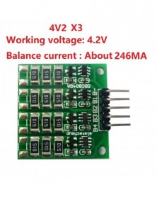
Szín: 4V2 X3 246MA - 1-4 cellás 3,7 V Li-ion polimer 3,2 V LiFePO4 lítium akkumulátorcsomagok Charge Balance BMS
330 Ft 674 FtProduct Name: 1-4 cell 3.7V Li-ion Polymer 3.2V LiFePO4 lithium Battery packs Charge Balance BMS Charger protection board for 18650 14500
Packing list:
1 PCS Multi-cell Cell Li-ion/Polymer/LiFePO4 Battery Charge Balance Module
Description:
4.2V(4V2) version:
Multi-cell 3.7V/4.2V Li-ion/Polymer Battery(packs) Charge Balance Module
(1) High Precision Voltage Detection Circuit
Overcharge detection voltage 4.000~4.500V Accuracy±25mV
Overcharge release voltage 3.800~4.500V Accuracy±35mV
Standby detection voltage 2.70V Accuracy±15%
Standby release voltage 2.70V Accuracy±15%
(2) Delay times are generated by an internal circuit (external capacitors are unnecessary).
(3) Low consumption current
Operation mode Typ. value 2.5μA, max. value: 3.5μA (VDD=3.9V)
Standby mode Max. value:0.5μA (VDD=2.7V)
(4)Wide operation temperature range: -40℃~ 85℃
Main control chip : HY2213-BB3A
Size : 30mm x 28mm x 8mm
Weight : 3.5g
3.6V(3V6) version:
Multi-cell 3.2V/3.6V LiFePO4 Battery(packs) Charge Balance Module
(1) High Precision Voltage Detection Circuit
Overcharge detection voltage 3.200~4.000V Accuracy±25mV
Overcharge release voltage 3.000~4.000V Accuracy±35mV
Standby detection voltage 2.70V Accuracy±15%
Standby release voltage 2.70V Accuracy±15%
(2) Delay times are generated by an internal circuit (external capacitors are unnecessary).
(3) Low consumption current
Operation mode Typ. value 2.5μA, max. value: 3.5μA (VDD=3.2V)
Standby mode Max. value:0.5μA (VDD=2.0V)
(4) Wide operation temperature range: -40℃~ 85℃
Main control chip : HY2212-BB3A
Size : 30mm x 28mm x 8mm
Weight : 3.5g
Please contact me for the chip manual.
The value of Rb is the value of 4 resistors connected in parallel.
The Balance current is determined by the value of the Rb1- Rb4 resistor. Changing the value of Rb1- Rb4 can change the Balance current
4.2V(4V2) version : Balance current(A)= 4.2/Rb
3.6V(3V6) version : Balance current(A)= 3.6/Rb
A single module can be used for a maximum of 4 batteries (battery packs), using 2 or more modules in series, and can be used for 5-40 batteries (battery packs) in series. -
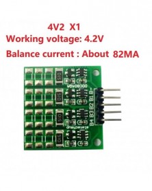
Szín: 4V2 X1 82MA - 1-4 cellás 3,7 V Li-ion polimer 3,2 V LiFePO4 lítium akkumulátorcsomagok Charge Balance BMS
330 Ft 674 FtProduct Name: 1-4 cell 3.7V Li-ion Polymer 3.2V LiFePO4 lithium Battery packs Charge Balance BMS Charger protection board for 18650 14500
Packing list:
1 PCS Multi-cell Cell Li-ion/Polymer/LiFePO4 Battery Charge Balance Module
Description:
4.2V(4V2) version:
Multi-cell 3.7V/4.2V Li-ion/Polymer Battery(packs) Charge Balance Module
(1) High Precision Voltage Detection Circuit
Overcharge detection voltage 4.000~4.500V Accuracy±25mV
Overcharge release voltage 3.800~4.500V Accuracy±35mV
Standby detection voltage 2.70V Accuracy±15%
Standby release voltage 2.70V Accuracy±15%
(2) Delay times are generated by an internal circuit (external capacitors are unnecessary).
(3) Low consumption current
Operation mode Typ. value 2.5μA, max. value: 3.5μA (VDD=3.9V)
Standby mode Max. value:0.5μA (VDD=2.7V)
(4)Wide operation temperature range: -40℃~ 85℃
Main control chip : HY2213-BB3A
Size : 30mm x 28mm x 8mm
Weight : 3.5g
3.6V(3V6) version:
Multi-cell 3.2V/3.6V LiFePO4 Battery(packs) Charge Balance Module
(1) High Precision Voltage Detection Circuit
Overcharge detection voltage 3.200~4.000V Accuracy±25mV
Overcharge release voltage 3.000~4.000V Accuracy±35mV
Standby detection voltage 2.70V Accuracy±15%
Standby release voltage 2.70V Accuracy±15%
(2) Delay times are generated by an internal circuit (external capacitors are unnecessary).
(3) Low consumption current
Operation mode Typ. value 2.5μA, max. value: 3.5μA (VDD=3.2V)
Standby mode Max. value:0.5μA (VDD=2.0V)
(4) Wide operation temperature range: -40℃~ 85℃
Main control chip : HY2212-BB3A
Size : 30mm x 28mm x 8mm
Weight : 3.5g
Please contact me for the chip manual.
The value of Rb is the value of 4 resistors connected in parallel.
The Balance current is determined by the value of the Rb1- Rb4 resistor. Changing the value of Rb1- Rb4 can change the Balance current
4.2V(4V2) version : Balance current(A)= 4.2/Rb
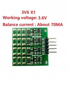
3.6V(3V6) version : Balance current(A)= 3.6/Rb
A single module can be used for a maximum of 4 batteries (battery packs), using 2 or more modules in series, and can be used for 5-40 batteries (battery packs) in series. -
Szín: 3V6 X1 70MA - 1-4 cellás 3,7 V Li-ion polimer 3,2 V LiFePO4 lítium akkumulátorcsomagok Charge Balance BMS
330 Ft 674 FtProduct Name: 1-4 cell 3.7V Li-ion Polymer 3.2V LiFePO4 lithium Battery packs Charge Balance BMS Charger protection board for 18650 14500
Packing list:
1 PCS Multi-cell Cell Li-ion/Polymer/LiFePO4 Battery Charge Balance Module
Description:
4.2V(4V2) version:
Multi-cell 3.7V/4.2V Li-ion/Polymer Battery(packs) Charge Balance Module
(1) High Precision Voltage Detection Circuit
Overcharge detection voltage 4.000~4.500V Accuracy±25mV
Overcharge release voltage 3.800~4.500V Accuracy±35mV
Standby detection voltage 2.70V Accuracy±15%
Standby release voltage 2.70V Accuracy±15%
(2) Delay times are generated by an internal circuit (external capacitors are unnecessary).
(3) Low consumption current
Operation mode Typ. value 2.5μA, max. value: 3.5μA (VDD=3.9V)
Standby mode Max. value:0.5μA (VDD=2.7V)
(4)Wide operation temperature range: -40℃~ 85℃
Main control chip : HY2213-BB3A
Size : 30mm x 28mm x 8mm
Weight : 3.5g
3.6V(3V6) version:
Multi-cell 3.2V/3.6V LiFePO4 Battery(packs) Charge Balance Module
(1) High Precision Voltage Detection Circuit
Overcharge detection voltage 3.200~4.000V Accuracy±25mV
Overcharge release voltage 3.000~4.000V Accuracy±35mV
Standby detection voltage 2.70V Accuracy±15%
Standby release voltage 2.70V Accuracy±15%
(2) Delay times are generated by an internal circuit (external capacitors are unnecessary).
(3) Low consumption current
Operation mode Typ. value 2.5μA, max. value: 3.5μA (VDD=3.2V)
Standby mode Max. value:0.5μA (VDD=2.0V)
(4) Wide operation temperature range: -40℃~ 85℃
Main control chip : HY2212-BB3A
Size : 30mm x 28mm x 8mm
Weight : 3.5g
Please contact me for the chip manual.
The value of Rb is the value of 4 resistors connected in parallel.
The Balance current is determined by the value of the Rb1- Rb4 resistor. Changing the value of Rb1- Rb4 can change the Balance current
4.2V(4V2) version : Balance current(A)= 4.2/Rb
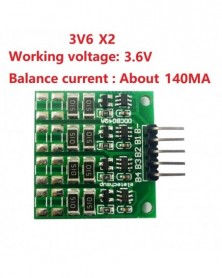
3.6V(3V6) version : Balance current(A)= 3.6/Rb
A single module can be used for a maximum of 4 batteries (battery packs), using 2 or more modules in series, and can be used for 5-40 batteries (battery packs) in series. -
Szín: 3V6 X2 140MA - 1-4 cellás 3,7 V Li-ion polimer 3,2 V LiFePO4 lítium akkumulátorcsomagok Charge Balance BMS
330 Ft 674 FtProduct Name: 1-4 cell 3.7V Li-ion Polymer 3.2V LiFePO4 lithium Battery packs Charge Balance BMS Charger protection board for 18650 14500
Packing list:
1 PCS Multi-cell Cell Li-ion/Polymer/LiFePO4 Battery Charge Balance Module
Description:
4.2V(4V2) version:
Multi-cell 3.7V/4.2V Li-ion/Polymer Battery(packs) Charge Balance Module
(1) High Precision Voltage Detection Circuit
Overcharge detection voltage 4.000~4.500V Accuracy±25mV
Overcharge release voltage 3.800~4.500V Accuracy±35mV
Standby detection voltage 2.70V Accuracy±15%
Standby release voltage 2.70V Accuracy±15%
(2) Delay times are generated by an internal circuit (external capacitors are unnecessary).
(3) Low consumption current
Operation mode Typ. value 2.5μA, max. value: 3.5μA (VDD=3.9V)
Standby mode Max. value:0.5μA (VDD=2.7V)
(4)Wide operation temperature range: -40℃~ 85℃
Main control chip : HY2213-BB3A
Size : 30mm x 28mm x 8mm
Weight : 3.5g
3.6V(3V6) version:
Multi-cell 3.2V/3.6V LiFePO4 Battery(packs) Charge Balance Module
(1) High Precision Voltage Detection Circuit
Overcharge detection voltage 3.200~4.000V Accuracy±25mV
Overcharge release voltage 3.000~4.000V Accuracy±35mV
Standby detection voltage 2.70V Accuracy±15%
Standby release voltage 2.70V Accuracy±15%
(2) Delay times are generated by an internal circuit (external capacitors are unnecessary).
(3) Low consumption current
Operation mode Typ. value 2.5μA, max. value: 3.5μA (VDD=3.2V)
Standby mode Max. value:0.5μA (VDD=2.0V)
(4) Wide operation temperature range: -40℃~ 85℃
Main control chip : HY2212-BB3A
Size : 30mm x 28mm x 8mm
Weight : 3.5g
Please contact me for the chip manual.
The value of Rb is the value of 4 resistors connected in parallel.
The Balance current is determined by the value of the Rb1- Rb4 resistor. Changing the value of Rb1- Rb4 can change the Balance current
4.2V(4V2) version : Balance current(A)= 4.2/Rb
3.6V(3V6) version : Balance current(A)= 3.6/Rb
A single module can be used for a maximum of 4 batteries (battery packs), using 2 or more modules in series, and can be used for 5-40 batteries (battery packs) in series. -
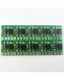
Szín: 3V6 X3 210MA - 1-4 cellás 3,7 V Li-ion polimer 3,2 V LiFePO4 lítium akkumulátorcsomagok Charge Balance BMS
330 Ft 674 FtProduct Name: 1-4 cell 3.7V Li-ion Polymer 3.2V LiFePO4 lithium Battery packs Charge Balance BMS Charger protection board for 18650 14500
Packing list:
1 PCS Multi-cell Cell Li-ion/Polymer/LiFePO4 Battery Charge Balance Module
Description:
4.2V(4V2) version:
Multi-cell 3.7V/4.2V Li-ion/Polymer Battery(packs) Charge Balance Module
(1) High Precision Voltage Detection Circuit
Overcharge detection voltage 4.000~4.500V Accuracy±25mV
Overcharge release voltage 3.800~4.500V Accuracy±35mV
Standby detection voltage 2.70V Accuracy±15%
Standby release voltage 2.70V Accuracy±15%
(2) Delay times are generated by an internal circuit (external capacitors are unnecessary).
(3) Low consumption current
Operation mode Typ. value 2.5μA, max. value: 3.5μA (VDD=3.9V)
Standby mode Max. value:0.5μA (VDD=2.7V)
(4)Wide operation temperature range: -40℃~ 85℃
Main control chip : HY2213-BB3A
Size : 30mm x 28mm x 8mm
Weight : 3.5g
3.6V(3V6) version:
Multi-cell 3.2V/3.6V LiFePO4 Battery(packs) Charge Balance Module
(1) High Precision Voltage Detection Circuit
Overcharge detection voltage 3.200~4.000V Accuracy±25mV
Overcharge release voltage 3.000~4.000V Accuracy±35mV
Standby detection voltage 2.70V Accuracy±15%
Standby release voltage 2.70V Accuracy±15%
(2) Delay times are generated by an internal circuit (external capacitors are unnecessary).
(3) Low consumption current
Operation mode Typ. value 2.5μA, max. value: 3.5μA (VDD=3.2V)
Standby mode Max. value:0.5μA (VDD=2.0V)
(4) Wide operation temperature range: -40℃~ 85℃
Main control chip : HY2212-BB3A
Size : 30mm x 28mm x 8mm
Weight : 3.5g
Please contact me for the chip manual.
The value of Rb is the value of 4 resistors connected in parallel.
The Balance current is determined by the value of the Rb1- Rb4 resistor. Changing the value of Rb1- Rb4 can change the Balance current
4.2V(4V2) version : Balance current(A)= 4.2/Rb
3.6V(3V6) version : Balance current(A)= 3.6/Rb
A single module can be used for a maximum of 4 batteries (battery packs), using 2 or more modules in series, and can be used for 5-40 batteries (battery packs) in series. -
Szín: 3V6 X4 280MA - 1-4 cellás 3,7 V Li-ion polimer 3,2 V LiFePO4 lítium akkumulátorcsomagok Charge Balance BMS
330 Ft 674 FtProduct Name: 1-4 cell 3.7V Li-ion Polymer 3.2V LiFePO4 lithium Battery packs Charge Balance BMS Charger protection board for 18650 14500
Packing list:
1 PCS Multi-cell Cell Li-ion/Polymer/LiFePO4 Battery Charge Balance Module
Description:
4.2V(4V2) version:
Multi-cell 3.7V/4.2V Li-ion/Polymer Battery(packs) Charge Balance Module
(1) High Precision Voltage Detection Circuit
Overcharge detection voltage 4.000~4.500V Accuracy±25mV
Overcharge release voltage 3.800~4.500V Accuracy±35mV
Standby detection voltage 2.70V Accuracy±15%
Standby release voltage 2.70V Accuracy±15%
(2) Delay times are generated by an internal circuit (external capacitors are unnecessary).
(3) Low consumption current
Operation mode Typ. value 2.5μA, max. value: 3.5μA (VDD=3.9V)
Standby mode Max. value:0.5μA (VDD=2.7V)
(4)Wide operation temperature range: -40℃~ 85℃
Main control chip : HY2213-BB3A
Size : 30mm x 28mm x 8mm
Weight : 3.5g
3.6V(3V6) version:
Multi-cell 3.2V/3.6V LiFePO4 Battery(packs) Charge Balance Module
(1) High Precision Voltage Detection Circuit
Overcharge detection voltage 3.200~4.000V Accuracy±25mV
Overcharge release voltage 3.000~4.000V Accuracy±35mV
Standby detection voltage 2.70V Accuracy±15%
Standby release voltage 2.70V Accuracy±15%
(2) Delay times are generated by an internal circuit (external capacitors are unnecessary).
(3) Low consumption current
Operation mode Typ. value 2.5μA, max. value: 3.5μA (VDD=3.2V)
Standby mode Max. value:0.5μA (VDD=2.0V)
(4) Wide operation temperature range: -40℃~ 85℃
Main control chip : HY2212-BB3A
Size : 30mm x 28mm x 8mm
Weight : 3.5g
Please contact me for the chip manual.
The value of Rb is the value of 4 resistors connected in parallel.
The Balance current is determined by the value of the Rb1- Rb4 resistor. Changing the value of Rb1- Rb4 can change the Balance current
4.2V(4V2) version : Balance current(A)= 4.2/Rb
3.6V(3V6) version : Balance current(A)= 3.6/Rb
A single module can be used for a maximum of 4 batteries (battery packs), using 2 or more modules in series, and can be used for 5-40 batteries (battery packs) in series. -
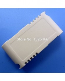
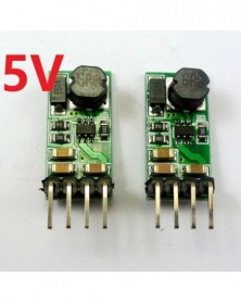
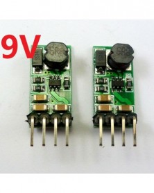
3,5 A DC DC átalakító 3,3 V 3,7 V - 5 V Step Up Boost tápegység modul
284 Ft 580 FtProduct Name: 3.5A DC DC Converter 3.3V 3.7V to 5V Step Up Boost Module
Packing list:
1 pcs Step-up Voltage Converter module (input 1.5-5V, output 5V ±5 % ) ;
1 pcs Plastic shell
Description:
Input voltage DC 1.5-5V, output DC 5V
Maximum output current: 3.5A
Start Voltage: 1.5V
Input 2.5V Output Current 5V 0.4A
Input 3V Output Current 5V 0.8A
Input 3.3V Output Current 5V 1.5A
Input 3.7V Output Current 5V 2.5A
Input above 4V Output Current 5V 3.5A
Conversion Efficiency: 80-90% (Typical)
Operating Temperature:Industrial main chip
Short circuit protection:No.(Please Install fuses or protection circuits at Input port)
Input Reverse Polarity Protection: No.Please Series diode at the input port
Size:50(L)*25(W)*9(H)mm
Note :
This is a DC-DC voltage converter module,Must be noted when using:
1 Input voltage can not be greater than the maximum input range
2 Output power can not be greater than the maximum load for a long time
3 Input power must be greater than the output power, because the power consumption of the module itself
Power supply Plastic shell:
Enclosure Material: PC
Outside diameter : 42 x 40 x 21
Inside diameter : 39 x 37 x 19
Applications:
Battery powered equipment
Wirel s mouse,Wireless keyboard
Network equipment,Router
Camera,Video camera
VCR
PDA
LED Lighting
Wireless communication equipment
MP3/MP4 player
Audio equipment
LED MOTOR -
6A nagy teljesítményű DC 2,7-5,5V-3,5-24V Step-Up Boost átalakító modul Li-ion Lipo UVLO PTZ IP kamera PLC Motro LED-hez
319 Ft 650 Ft
Product Name : 6A High-power DC 2.7-5.5V to 3.5-24V Step-Up Boost Converter Module for Li-ion Lipo UVLO PTZ IP Camera PLC Motro LED
Packing list:
1 PCS DD03AJTA 30W high-power adjustable boost module
Description:
30W high-power adjustable boost module
Input DC 2.7-5.5V,Adjustable Output DC 3.5-24V
Maximum output power 30W(See the table for details)
Maximum input current: 8A(See the table for details)
Maximum output current: 6A(See the table for details)
Quiescent current: about 1MA
Efficiency : >=96%
Switching Frequency : 600KHz fixed
Overtemperature shutdown, input under-voltage protection and short circuit protection.
UVLO Low Threshold 2.6V,UVLO High Threshold 3.2V,suitable for 3.7V lithium battery power supply
Operating Ambient Temperature : -40 to 85 °C
Storage Temperature : -55 to 150°C
Size : 45*20*15mm
Weight : 8g
Attention :
This is a high-power boost module. Please pay attention to the following when using:
1 The power supply must be sufficient. If the module needs to output 30W power, the power supply must be greater than 40W.
2 The power and boost module leads must be thick enough (can pass 10A) and soldered well.
3 Use a multimeter to directly measure the ''VIN GND'' port to determine if the power is sufficient. If the voltage is lower than the power supply 1V, the power supply is insufficient or there is no good connection.
4 Input voltage can not be greater than the maximum input range
5 Output power can not be greater than the maximum load for a long time
6 Input power must be greater than the output power, because the power consumption of the module itself
Applications:
for QC2.0 3.0 charger
for 3.7V li-on Lithium Battery 18650
PTZ CCTV IP camera
Smart home / home automation
WIFI Router Switch Network equipment
LED Motor
-
2db Kis méret!! DC-DC 12V–5V Step Down Buck Converter Tápegység modul Arduino Breadboard Raspberry pi 2 MCU-hoz
264 Ft 539 FtProduct Name : 2pcs Small Size!! DC-DC 12V to 5V Step Down Buck Converter Power supply Module for Arduiu o Breadboard raspberry pi 2 MCU
Packing list:
2 PCS DC-DC 12V to 5V Step Down Buck Power supply Module
Description:
Input voltage 6.5~23V,output 5V -5%
Maximum output current 1.2A,Short time maximum output current 2A
DC-DC Step-Down Converter module working frequency 1.4MHz. efficiency is 80-92% .
2.54mm pin pitch, Arduiuo UNO MEGA2560 Breadboard MCU Development Board friendly
Excluding Pin Size 22.5mm x 13.5mm x 6.5mm( small)
Weight : about 2.2g( Very light)
Applications:
MCU Development Board,FPGA/CPLD UNO MEGA2560 DUE 8051 AVR C8051 etc
raspberry pi 2
5V LED Lighting
5V Motor
Mobile phone charger
Wireless communication equipment
Smart home / home automation
315M 433M Wireless remote controller
Distributed Power Systems
Battery Charger
Pre-Regulator for Linear Regulators
DSL Modems
Attention :
This is a DC-DC voltage converter module,Must be noted when using:
1 Input voltage can not be greater than the maximum input range
2 Output power can not be greater than the maximum load for a long time
3 Input power must be greater than the output power, because the power consumption of the module itself
-
10 DB UNO MEGA2560 példakóddal! 3.3V 5V 4 gomb 1 Analóg kimenet AD billentyűzet billentyűzet gomb Arduinohoz
1 040 Ft 2 122 FtProduct Name:10PCS with UNO MEGA2560 example Code ! 3.3V 5V 4 Buttons 1 Analog output AD Keypad keyboard button for Arduiuo
Packing list:
10 p cs 4 key Analog Buttons( With Pin Header )
Description:
1 Power Supply Voltage : 3-5V
2 4 Buttons 1 Analog Output(AD Pin)
3 PCB Size : 30x12mm
4 Weight : 1.8g
Ideal for linking up to your Ardiuno UNO Mini Nano Mega2560 etc,or others MCU ( AVR STM32 ARM7 ARM9 ARM10 PIC AT89C51 STC MSP430 FPGA CPLD raspberry pi etc.)
Circuit schematics :
Connection with Arduiuo UNO :
Arduiuo uno/mega2560 Code
//******************************************************//
/*
Arduiuo_4 key analog Buttons
This example code is in the public domain.
*/
#define key1ValueMin 96
#define key1ValueMax 106
#define key2ValueMin 144
#define key2ValueMax 159
#define key3ValueMin 193
#define key3ValueMax 213
#define key4ValueMin 242
#define key4ValueMax 255
int adPin = A0; // select the input pin for the potentiometer
int keyValue;
int keyValue_r;
int keyValue_rr;
//key scan
int key_scan(void)
{
int adValue;
int key;
adValue = analogRead(adPin);//read ad Value
adValue = adValue / 4;
if(adValue >= key1ValueMin && adValue <= key1ValueMax)// k1
{
key = 1;
}
else if(adValue >= key2ValueMin && adValue <= key2ValueMax)// k2
{
key = 2;
}
else if(adValue >= key3ValueMin && adValue <= key3ValueMax)// k3
{
key = 3;
}
else if(adValue >= key4ValueMin)// k4
{
key = 4;
}
else //Invalid value
{
key = 0;
}
return key;
}
void setup() {
Serial.begin(9600);
}
void loop() {
//Save three key scan value
keyValue_rr = keyValue_r;
keyValue_r = keyValue;
keyValue = key_scan();
//Three scanned values are the same, indicating that key is valid
if(keyValue > 0 && keyValue==keyValue_r && keyValue_r==keyValue_rr)
{
Serial.print(''keyValue = '');
Serial.println(keyValue);
}
delay(100); //Each scan interval 100-200MS
}
//******************************************************// -
10x 3,7 V Li-ion Li-ion akkumulátor 4,2 V töltő 3 A túltöltés kisülés elleni védelmi modul 18650 TP4056 mobil
445 Ft 909 Ft
Protects a single 3.7V lithium battery:
Protect multiple 3.7V lithium batteries (no more than 10pcs recommended):
DIY mobile power(This application you need DD05CVSA, Click here)
Product Name: 10x 3.7V Li-ion Lithium Battery 4.2V Charger 3A Over Charge Discharge Protection Module for 18650 TP4056 mobile power Diy
Packing list:
10 PCS 3.7V 4.2V 3A Charger Over Charge Discharge Protection Board
Description:
Functions:
Over Charge Protection
Over Discharge Protection
Short Circuit Protection
Overcurrent Protection
Parameters:
Over Charge Detection Voltage: 4.28±0.05V
Over Charge Release Voltage: 4.26±0.05V
Over Discharge Detection Voltage: 2.5±0.1V
Over current Detection Current: 1-3A
Overcurrent protection : 3.2±0.2A
Size : 12.6x10.2x2.1mm
Weight : 0.34g
Note: Please charge the first time, activate the protection board. Otherwise there is no voltage output
Wiring:
B- connected to battery negative
B connected to battery positive
P Connect the charger/load positive
P- Connect the charger/load negative
Applications
3.7V lithium battery 18650
TP4056 Charging module
-
8 DB 1,5 V 3 V 3,3 V 3,7 V 4,5 V – 5 V DC DC Step UP Kapcsoló tápegység műszerekhez LED motoros játék
482 Ft 983 Ft
Product Name: 8PCS 1.5V 3V 3.3V 3.7V to 5V DC DC Step UP Switching Power Supply Board for Instruments LED Motor Toy
Packing list:
8 PCS DC DC 1-5V to 5V Step UP Converter
Description:
Input voltage 0.9~ 5V,output 5V
Maximum output current: 480 MA,
Start Voltage 0.8V, Output Current 7MA
INPUT 1-1.5V, OUTPUT 5V 40-100MA;
INPUT 1.5-2V, OUTPUT 5V 100-150MA;
INPUT 2-3V, OUTPUT 5V 150-380MA;
INPUT above 3V, OUTPUT 5V 380-480MA;
DC-DC Boost module working frequency 150KHZ. efficiency <85% (Recommended high efficiency version).
2.54mm pin pitch.
Excluding Pin Size 11mm x 10.5mm x 7.5mm(Very small).
Weight : about 1g( Very light)
Applications:
Battery powered equipment
Instruments LED Motor Toy
Wireless Module,NRF24L01 CC1101 CC2500 etc.
Development Board,FPGA/CPLD UNO MEGA2560 PRO MINI ARM 8051 C8051 AVR STC etc
Camera, Video camera
VCR
PDA
LED Lighting
Wireless communication equipment
MP3/MP4 player
Audio equipment
Attention :
This is a DC-DC voltage converter module,Must be noted when using:
1 Input voltage can not be greater than the maximum input range
2 Output power can not be greater than the maximum load for a long time
3 Input power must be greater than the output power, because the power consumption of the module itself
Q & A:
Q : Why output voltage is less than the nominal voltage
A : Input power supply power is too low.Test the input voltage with a multimeter, a t this time of the input voltage is very low
-
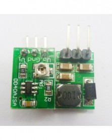
2db 1A mini DC DC Step Down átalakító modul 24V 12V 9V - 5V 3.3V 3V állítható kimenet Arduino DUE UNO Breadboardhoz
319 Ft 650 FtNote: Adjustable resistors (potentiometers) are components that are easily damaged. Use a suitable screwdriver to slowly rotate. Click here to buy a screwdriver.
Applications:
1.2V/1.5V/1.8V/2.5V/3.3V/5V MCU ARM CPU FPGA/CPLD
12V 5V TO 3.7V lithium battery-powered systems
12V 9V 6V 5V 3.3V Motor
WIFI esp8266 Module
CCTV camera
Wireless Module:Nrf24l01 CC1101 CC2500 CC2530 Zigbee
Smart home / home automation
315M 433M Wireless remote controller
Distributed Power Systems
Battery Charger
Pre-Regulator for Linear Regulators
DSL Modems
Product Name : 2pcs 5W DC-DC Buck Power Board 5V-36V to 5 12V 24v car Power Module 78L05 78L12
Module No.: CE_DD40AJSA
Packing list:
2 PCS mini 1A DC DC Converter Step Down 4.75V-40V to 0.8-30V Adjustable output
Description:
Input voltage 4.75~40V,Adjustable output 0.9~30V
Long time maximum output current 0.8A(12V to 5V)
Short time maximum output current 1A(12V to 5V)
Quiescent current: about 1.5MA
DC-DC Step-Down Converter module working frequency 550KHz. efficiency is 75-90% .
Overtemperature shutdown, input under-voltage protection, BS-voltage protection, and short circuit protection.
2.54mm pin pitch, Arduiuo UNO MEGA2560 Breadboard MCU Development Board friendly
Excluding Pin Size 15mm x 10.3mm x 6.8mm(Very small)
Weight : about 1.5g(Very light)
Attention :
This is a DC-DC voltage converter module,Must be noted when using:
1 Input voltage can not be greater than the maximum input range
2 Output power can not be greater than the maximum load for a long time
3 Input power must be greater than the output power, because the power consumption of the module itself
-
8db 500MA 0,8-3,3V-3,3V DC DC Boost Switch tápegység modul
482 Ft 983 Ft
Product Name: 8pcs 500MA 0.8-3.3V to 3.3V DC DC Boost Switch power Supply Module
Packing list:
8 pcs 500MA 0.8-3.3V to 3.3V DC DC Boost Switch power Supply Module
Description:
Input voltage 0.8 ~ 3.3V,output 3.3V
Maximum output current: 500 MA,
Start Voltage 0.8V, Output Current 8MA
INPUT 1-1.5V, OUTPUT 3.3V 50-110MA;
INPUT 1.5-2V, OUTPUT 3.3V 110-160MA;
INPUT 2-3V, OUTPUT 3.3V 160-400MA;
INPUT above 3V, OUTPUT 3.3V 400-500MA;
DC-DC Boost module working frequency 150KHZ. efficiency <85% (Recommended high efficiency version) .
2.54mm pin pitch.
Excluding Pin Size 11mm x 10.5mm x 7.5mm(Very small).
Weight : about 1g( Very light)
Applications:
Battery powered equipment
Wirels Module,NRF24L01 CC1101 CC2500 SI4432 SI4463 etc.
3.3V MCU Development Board,Xilinx Altera FPGA/CPLD ARM AVR PIC
Camera, Video camera
3.3V Low power motors
PDA
LED Lighting
Wireless communication equipment
MP3/MP4 player
Audio equipment
Attention :
This is a DC-DC voltage converter module,Must be noted when using:
1 Input voltage can not be greater than the maximum input range
2 Output power can not be greater than the maximum load for a long time
3 Input power must be greater than the output power, because the power consumption of the module itself
Q & A:
Q : Why output voltage is less than the nominal voltage
A : Input power supply power is too low.Test the input voltage with a multimeter, a t this time of the input voltage is very low -
2 DB DC 3,7 V 5 V 12 V LED illesztőprogram érintőképernyős vezérlés a 3528 5050 LED szalaghoz 18650 Li-ion
349 Ft 712 FtEasy to use :
Touch the "touch area", touch once "Turn on",Touch again "Turn off"
When "Turn on", Continuous touch reduce the brightness,Once again Continuous touch Increased brightness,And so on
Product Name: 2PCS DC 3.7V 5V 12V LED Driver Touch Control for 3528 5050 LED strip 18650 Li-ion
Packing list:
2 PCS DC 3.3-12V 2A Touch Switch LED Driver Controller
Description:
Working voltage : DC 3.3-13V(Perfect for 3.7V 5V 6V 9V 12V LED Driver)
Output Current: 30-2000MA
Maximum output power: 26W
Continuously adjustable brightness
Turn off consumption is only 10uA
Pin Size 31mm x 15mm x 3mm
Weight : about 1.3g
-
10db Nagyon kicsi DC DC Step-Up Boost Voltage Converter 3,3V 3,7V 4,2V-5V modul Wifi lítium napelemes töltőhöz
445 Ft 909 Ft
Applications:
Low-power LED Driver
White LED Backlighting
Li-Ion Battery Backup Supplies
Local 3.3V to 5V Conversion
Smart Card Readers
PCMCIA Local 5V Supplies
Product Name: 10pcs mini DC DC Step-Up Boost Voltage Converter 3.3V 3.7V 4.2V to 5V Module for Wifi Bluetooth lithium battery Solar charger
Packing list:
10 PCS DD0505MC 250MA 3V-5V to 5V DC DC Boost Converter
This is a micro-power( only 250MA ) DC-DC Step-Up Converter module.
If you need 1200MA 3V-5V to 5V Boost module ,Click here
If you need 1200MA 5V-23V to 5V Buck module ,Click here
Description:
Low Noise, Regulated Charge Pump DC/DC Converter
It produce a regulated output voltage from a 2.7V to 4.5V input with up to 250mA of output current
Fixed 5V -4% Output
Voltage Input Range: 2.7~5V
Long time maximum output current 200mA
Short time maximum output current 250mA
working frequency 1.2MHz.
Short-Circuit Protection
No load input current : 1.8mA
2.54mm pin pitch, Arduiuo Breadboard MCU Development Board friendly
Excluding Pin Size 11mm x 7.62mm x 2.4mm(Very very small)
Weight : about 0.47g(Very very light)
Attention :
This is a DC-DC voltage converter module,Must be noted when using:
1 Input voltage can not be greater than the maximum input range
2 Output power can not be greater than the maximum load for a long time
3 Input power must be greater than the output power, because the power consumption of the module itself
-
Szín: Késleltetett relé - DC 12V önzáró relé PLC ciklusidőzítő modul késleltetési idő kapcsoló PIR-hez
400 Ft 817 Ft
Product Name : DC 12V Self-lock Relay PLC Cycle Timer Module Delay Time Switch for PIR Microwave radar Infrared Vibration Touch sensor
Packing list(Please choose the module you need when purchasing)
1 PCS Delay Relay OR 1 PCS PIR Sensor OR 1 PCS Radar Sensor
Description:
1 Working voltage: DC 12V
2 Working current: standby 7-8MA, Relay Open 64MA
3 Working modes : Delay_1 (seconds), Non-locking (Momentary),Synchronization, Self-locking (Toggle),Delay_2 (minutes)
4 5V/50MA power output interface, Sensor Control interface (High level trigger), Switch control interface (Low level trigger)
5 Size: 52*30*18 mm
6 Weight: 18 grams
7 Maximum load: 20A/14VDC, 20A/125VAC
Function Description:
1 Pin Description
VIN : Power input positive
GND : Power input negative
NC : Relay normally closed
COM : Relay Common
NO : Relay normally open
Vo : 5V/50MA power output positive, power the sensor
D : Sensor Control Interface (high level trigger)
G : 5V/50MA power output negative
T : Switching control interface (low level trigger)
2 Mode selection
Relay open: COM connected NO but disconnected NC
Relay close: COM disconnected NO but NC connected COM.
3 Input control
1 Switch control (low level trigger) wiring diagram
2 Switching Sensor control (high level trigger) wiring diagram
Supports the following (but not limited to) switching sensors :
RCWL-0516 Microwave radar sensor
HC-SR505 Infrared sensor
SW-420 Vibration sensor
Photosensitive sensor
Flame sensor
MQ-2 Smoke sensor
Microphone sensor
Touch sensor
Reed switch sensor
Wiring diagram:
-
Szín: radarérzékelő - DC 12V önzáró relé PLC ciklusidőzítő modul késleltetési idő kapcsoló PIR-hez Mikrohullámú
220 Ft 448 Ft
Product Name : DC 12V Self-lock Relay PLC Cycle Timer Module Delay Time Switch for PIR Microwave radar Infrared Vibration Touch sensor
Packing list(Please choose the module you need when purchasing)
1 PCS Delay Relay OR 1 PCS PIR Sensor OR 1 PCS Radar Sensor
Description:
1 Working voltage: DC 12V
2 Working current: standby 7-8MA, Relay Open 64MA
3 Working modes : Delay_1 (seconds), Non-locking (Momentary),Synchronization, Self-locking (Toggle),Delay_2 (minutes)
4 5V/50MA power output interface, Sensor Control interface (High level trigger), Switch control interface (Low level trigger)
5 Size: 52*30*18 mm
6 Weight: 18 grams
7 Maximum load: 20A/14VDC, 20A/125VAC
Function Description:
1 Pin Description
VIN : Power input positive
GND : Power input negative
NC : Relay normally closed
COM : Relay Common
NO : Relay normally open
Vo : 5V/50MA power output positive, power the sensor
D : Sensor Control Interface (high level trigger)
G : 5V/50MA power output negative
T : Switching control interface (low level trigger)
2 Mode selection
Relay open: COM connected NO but disconnected NC
Relay close: COM disconnected NO but NC connected COM.
3 Input control
1 Switch control (low level trigger) wiring diagram
2 Switching Sensor control (high level trigger) wiring diagram
Supports the following (but not limited to) switching sensors :
RCWL-0516 Microwave radar sensor
HC-SR505 Infrared sensor
SW-420 Vibration sensor
Photosensitive sensor
Flame sensor
MQ-2 Smoke sensor
Microphone sensor
Touch sensor
Reed switch sensor
Wiring diagram:
-
Szín: PIR érzékelő - DC 12V önzáró relé PLC ciklusidőzítő modul késleltetési idő kapcsoló PIR-hez Mikrohullámú
236 Ft 481 Ft
Product Name : DC 12V Self-lock Relay PLC Cycle Timer Module Delay Time Switch for PIR Microwave radar Infrared Vibration Touch sensor
Packing list(Please choose the module you need when purchasing)
1 PCS Delay Relay OR 1 PCS PIR Sensor OR 1 PCS Radar Sensor
Description:
1 Working voltage: DC 12V
2 Working current: standby 7-8MA, Relay Open 64MA
3 Working modes : Delay_1 (seconds), Non-locking (Momentary),Synchronization, Self-locking (Toggle),Delay_2 (minutes)
4 5V/50MA power output interface, Sensor Control interface (High level trigger), Switch control interface (Low level trigger)
5 Size: 52*30*18 mm
6 Weight: 18 grams
7 Maximum load: 20A/14VDC, 20A/125VAC
Function Description:
1 Pin Description
VIN : Power input positive
GND : Power input negative
NC : Relay normally closed
COM : Relay Common
NO : Relay normally open
Vo : 5V/50MA power output positive, power the sensor
D : Sensor Control Interface (high level trigger)
G : 5V/50MA power output negative
T : Switching control interface (low level trigger)
2 Mode selection
Relay open: COM connected NO but disconnected NC
Relay close: COM disconnected NO but NC connected COM.
3 Input control
1 Switch control (low level trigger) wiring diagram
2 Switching Sensor control (high level trigger) wiring diagram
Supports the following (but not limited to) switching sensors :
RCWL-0516 Microwave radar sensor
HC-SR505 Infrared sensor
SW-420 Vibration sensor
Photosensitive sensor
Flame sensor
MQ-2 Smoke sensor
Microphone sensor
Touch sensor
Reed switch sensor
Wiring diagram:
-
10 DB AD Keypad 4 Kiegészítő kártya mátrix gombokkal vezérelt ADC portos billentyűzet
1 040 Ft 2 122 FtProduct Name: 10PCS AD Keypad]4 Accessory board matrix buttons controlled ADC port keyboard
Packing list:
10 pcs 4 key AD Keyboard
Description:
1 Power Supply Voltage : 2-5V
2 4 Buttons 1 Analog Output(AD Pin)
3 PCB Size : 30x12mm
4 Weight : 1.5g
Ideal for linking up to your Ardiuno UNO Mini Nano Mega2560 etc,or others MCU ( AVR STM32 ARM7 ARM9 ARM10 PIC AT89C51 STC MSP430 FPGA CPLD etc.)
Circuit schematics :
Connection with Arduiuo UNO :
Arduiuo uno/mega2560 Code
//******************************************************//
/*
Arduiuo_4 key analog Buttons
This example code is in the public domain.
*/
#define key1ValueMin 96
#define key1ValueMax 106
#define key2ValueMin 144
#define key2ValueMax 159
#define key3ValueMin 193
#define key3ValueMax 213
#define key4ValueMin 242
#define key4ValueMax 255
int adPin = A0; // select the input pin for the potentiometer
int keyValue;
int keyValue_r;
int keyValue_rr;
//key scan
int key_scan(void)
{
int adValue;
int key;
adValue = analogRead(adPin);//read ad Value
adValue = adValue / 4;
if(adValue >= key1ValueMin && adValue <= key1ValueMax)// k1
{
key = 1;
}
else if(adValue >= key2ValueMin && adValue <= key2ValueMax)// k2
{
key = 2;
}
else if(adValue >= key3ValueMin && adValue <= key3ValueMax)// k3
{
key = 3;
}
else if(adValue >= key4ValueMin)// k4
{
key = 4;
}
else //Invalid value
{
key = 0;
}
return key;
}
void setup() {
Serial.begin(9600);
}
void loop() {
//Save three key scan value
keyValue_rr = keyValue_r;
keyValue_r = keyValue;
keyValue = key_scan();
//Three scanned values are the same, indicating that key is valid
if(keyValue > 0 && keyValue==keyValue_r && keyValue_r==keyValue_rr)
{
Serial.print("keyValue = ");
Serial.println(keyValue);
}
delay(100); //Each scan interval 100-200MS
}
//******************************************************// -
30W DC-DC 3-6.8V DC 12V Step Up Boost Voltage Converter Tápegység UPS modul 3.3V 3.7V 4V 4.5V 5V 6V Wifi LED motorhoz
370 Ft 755 FtProduct Name: 30W DC-DC 3-6.8V to DC 12V Step Up Boost Voltage Converter Power Supply UPS Module in 3.3V 3.7V 4V 4.5V 5V 6V for Wifi LED Motor
Packing list:
1 pcs Step-up Voltage Converter module (input 3-6.8V, output 12V ±5 % ) ;
1 pcs Plastic shell
Description:
Module Properties: non-isolated step-up BOOST module
Input voltage DC 3-6.8V,output DC 12V
Maximum output current: 2.5A
Input 3.3V Output Current 12V 0.5MA
Input 3.7V Output Current 12V 1A
Input 5V Output Current 12V 2A
Input above 6V Output Current 12V 2.5A
Conversion Efficiency: 80-90% (Typical)
Operating Temperature:Industrial main chip
Short circuit protection:No.(Please Install fuses or protection circuits at Input port)
Input Reverse Polarity Protection: No.Please Series diode at the input port
Size:50(L)*25(W)*9(H)mm
Note :
1: Input voltage cannot bigger than the output , or boost part does not work. Voltage difference cannot be more than three times ,or the output power is limited !
2: No-load current: 12V output board (IN 5V = 22mA,6V = 17mA );
This is a DC-DC voltage converter module,Must be noted when using:
1 Input voltage can not be greater than the maximum input range
2 Output power can not be greater than the maximum load for a long time
3 Input power must be greater than the output power, because the power consumption of the module itself
Power supply Plastic shell:
Enclosure Material: PC
Outside diameter : 42 x 40 x 21
Inside diameter : 39 x 37 x 19 -
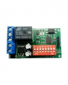
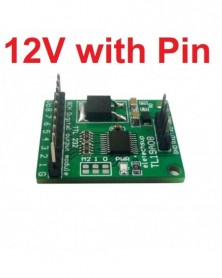
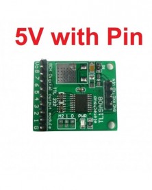
Szín: 12V tűvel - DC 5V 12V 8ch Modbus Rtu UART TTL232 IO vezérlőmodul az Arduino UNO MEGA relé PLC kenyértáblához
254 Ft 518 Ft
Product Name: DC 5V 12V 8ch Modbus Rtu UART TTL232 IO Control Module for Arduiuo UNO MEGA Relay PLC Breadboard
Package inlcuded:
1 x 5V/12V 8 Channel Multifunction RS232(TTL Lever) Control Board for 1-8 CH Relay Module
Description:
1 Working voltage: DC 5V (5V version) / DC 6-24V (12V version)
2 Working current: 8-13MA
3 Two command control modes: AT command and MODBUS command
4 The maximum delay under the AT command is 9999 seconds, and the maximum delay under the MODBUS command is 255 seconds
5 AT commands can be input by the serial port super terminal (serial assistant);
MODBUS commands can also be input by ''Modbus Poll'' in addition to the serial port super terminal input
6 RS232 (TTL level) input interface(2.54MM Pin)
7 8 output control pins(2.54MM Pin), 5V TTL level, low level (default)/high level output
8 Four versions: 12V with needle/12V without needle/5V with needle/5V without needle
9 Size: 30*25.4*2MM
10 Weight: 4.5g with Pin, 3.5g no Pin
Instruction manual Please ask us after the purchase
Application
Automated industry PLC
UNO MEGA Relay Module
Smart Home,Home Automation ;
Identification system;
Motor FW & BW;
CCTV Camera PTZ Control;
Security system;
LED dot matrix screen;
RS232 RS485 remote control;
Command mode selection :( figure above) M0 disconnect is MODBUS command mode. M0 Connect is AT command mode.
Output level selection : ( figure above) M1 disconnect is Low level output. M1 Connect is Hight level output
Slave ID: Different ''Sliver ID'' can be set by command, the maximum number is 247
Under the MODBUS command mode,the slave ID must be correct
command Description, Please refer to '' TL19A08 8-channel TTL output module commamd''
Typical applications:
1 AT command mode (M0 Connect), in this mode can be through the serial HyperTerminal (serial assistant) enter a simple AT command control relay. AT command mode time up to 9999 seconds
2 MODBUS command mode (M0 disconnect), you can control a variety of ways: Serial Hyper Terminal Control (need to manually add the CRC), Modbus Poll software control (software automatically add the CRC), PLC or MCU process control
It can control 1-8 channels 5V/6V/9V/12V/24V Relay Module
With RS485 interface and RS232 (TTL) interface
12V 5V version relay wiring diagram
Test Software(We offer a demo video):
Serial HyperTerminal:
Modbus Poll
-
Szín: 12V tű nélkül - DC 5V 12V 8ch Modbus Rtu UART TTL232 IO vezérlőmodul az Arduino UNO MEGA relé PLC kenyértáblához
234 Ft 477 Ft
Product Name: DC 5V 12V 8ch Modbus Rtu UART TTL232 IO Control Module for Arduiuo UNO MEGA Relay PLC Breadboard
Package inlcuded:
1 x 5V/12V 8 Channel Multifunction RS232(TTL Lever) Control Board for 1-8 CH Relay Module
Description:
1 Working voltage: DC 5V (5V version) / DC 6-24V (12V version)
2 Working current: 8-13MA
3 Two command control modes: AT command and MODBUS command
4 The maximum delay under the AT command is 9999 seconds, and the maximum delay under the MODBUS command is 255 seconds
5 AT commands can be input by the serial port super terminal (serial assistant);
MODBUS commands can also be input by ''Modbus Poll'' in addition to the serial port super terminal input
6 RS232 (TTL level) input interface(2.54MM Pin)
7 8 output control pins(2.54MM Pin), 5V TTL level, low level (default)/high level output
8 Four versions: 12V with needle/12V without needle/5V with needle/5V without needle
9 Size: 30*25.4*2MM
10 Weight: 4.5g with Pin, 3.5g no Pin
Instruction manual Please ask us after the purchase
Application
Automated industry PLC
UNO MEGA Relay Module
Smart Home,Home Automation ;
Identification system;
Motor FW & BW;
CCTV Camera PTZ Control;
Security system;
LED dot matrix screen;
RS232 RS485 remote control;
Command mode selection :( figure above) M0 disconnect is MODBUS command mode. M0 Connect is AT command mode.
Output level selection : ( figure above) M1 disconnect is Low level output. M1 Connect is Hight level output
Slave ID: Different ''Sliver ID'' can be set by command, the maximum number is 247
Under the MODBUS command mode,the slave ID must be correct
command Description, Please refer to '' TL19A08 8-channel TTL output module commamd''
Typical applications:
1 AT command mode (M0 Connect), in this mode can be through the serial HyperTerminal (serial assistant) enter a simple AT command control relay. AT command mode time up to 9999 seconds
2 MODBUS command mode (M0 disconnect), you can control a variety of ways: Serial Hyper Terminal Control (need to manually add the CRC), Modbus Poll software control (software automatically add the CRC), PLC or MCU process control
It can control 1-8 channels 5V/6V/9V/12V/24V Relay Module
With RS485 interface and RS232 (TTL) interface
12V 5V version relay wiring diagram
Test Software(We offer a demo video):
Serial HyperTerminal:
Modbus Poll
-
Szín: 5V tűvel - DC 5V 12V 8ch Modbus Rtu UART TTL232 IO vezérlőmodul az Arduino UNO MEGA relé PLC kenyértáblához
254 Ft 518 Ft
Product Name: DC 5V 12V 8ch Modbus Rtu UART TTL232 IO Control Module for Arduiuo UNO MEGA Relay PLC Breadboard
Package inlcuded:
1 x 5V/12V 8 Channel Multifunction RS232(TTL Lever) Control Board for 1-8 CH Relay Module
Description:
1 Working voltage: DC 5V (5V version) / DC 6-24V (12V version)
2 Working current: 8-13MA
3 Two command control modes: AT command and MODBUS command
4 The maximum delay under the AT command is 9999 seconds, and the maximum delay under the MODBUS command is 255 seconds
5 AT commands can be input by the serial port super terminal (serial assistant);
MODBUS commands can also be input by ''Modbus Poll'' in addition to the serial port super terminal input
6 RS232 (TTL level) input interface(2.54MM Pin)
7 8 output control pins(2.54MM Pin), 5V TTL level, low level (default)/high level output
8 Four versions: 12V with needle/12V without needle/5V with needle/5V without needle
9 Size: 30*25.4*2MM
10 Weight: 4.5g with Pin, 3.5g no Pin
Instruction manual Please ask us after the purchase
Application
Automated industry PLC
UNO MEGA Relay Module
Smart Home,Home Automation ;
Identification system;
Motor FW & BW;
CCTV Camera PTZ Control;
Security system;
LED dot matrix screen;
RS232 RS485 remote control;
Command mode selection :( figure above) M0 disconnect is MODBUS command mode. M0 Connect is AT command mode.
Output level selection : ( figure above) M1 disconnect is Low level output. M1 Connect is Hight level output
Slave ID: Different ''Sliver ID'' can be set by command, the maximum number is 247
Under the MODBUS command mode,the slave ID must be correct
command Description, Please refer to '' TL19A08 8-channel TTL output module commamd''
Typical applications:
1 AT command mode (M0 Connect), in this mode can be through the serial HyperTerminal (serial assistant) enter a simple AT command control relay. AT command mode time up to 9999 seconds
2 MODBUS command mode (M0 disconnect), you can control a variety of ways: Serial Hyper Terminal Control (need to manually add the CRC), Modbus Poll software control (software automatically add the CRC), PLC or MCU process control
It can control 1-8 channels 5V/6V/9V/12V/24V Relay Module
With RS485 interface and RS232 (TTL) interface
12V 5V version relay wiring diagram
Test Software(We offer a demo video):
Serial HyperTerminal:
Modbus Poll
-
Szín: 5V tű nélkül - DC 5V 12V 8ch Modbus Rtu UART TTL232 IO vezérlőmodul az Arduino UNO MEGA relé PLC kenyértáblához
234 Ft 477 Ft
Product Name: DC 5V 12V 8ch Modbus Rtu UART TTL232 IO Control Module for Arduiuo UNO MEGA Relay PLC Breadboard
Package inlcuded:
1 x 5V/12V 8 Channel Multifunction RS232(TTL Lever) Control Board for 1-8 CH Relay Module
Description:
1 Working voltage: DC 5V (5V version) / DC 6-24V (12V version)
2 Working current: 8-13MA
3 Two command control modes: AT command and MODBUS command
4 The maximum delay under the AT command is 9999 seconds, and the maximum delay under the MODBUS command is 255 seconds
5 AT commands can be input by the serial port super terminal (serial assistant);
MODBUS commands can also be input by ''Modbus Poll'' in addition to the serial port super terminal input
6 RS232 (TTL level) input interface(2.54MM Pin)
7 8 output control pins(2.54MM Pin), 5V TTL level, low level (default)/high level output
8 Four versions: 12V with needle/12V without needle/5V with needle/5V without needle
9 Size: 30*25.4*2MM
10 Weight: 4.5g with Pin, 3.5g no Pin
Instruction manual Please ask us after the purchase
Application
Automated industry PLC
UNO MEGA Relay Module
Smart Home,Home Automation ;
Identification system;
Motor FW & BW;
CCTV Camera PTZ Control;
Security system;
LED dot matrix screen;
RS232 RS485 remote control;
Command mode selection :( figure above) M0 disconnect is MODBUS command mode. M0 Connect is AT command mode.
Output level selection : ( figure above) M1 disconnect is Low level output. M1 Connect is Hight level output
Slave ID: Different ''Sliver ID'' can be set by command, the maximum number is 247
Under the MODBUS command mode,the slave ID must be correct
command Description, Please refer to '' TL19A08 8-channel TTL output module commamd''
Typical applications:
1 AT command mode (M0 Connect), in this mode can be through the serial HyperTerminal (serial assistant) enter a simple AT command control relay. AT command mode time up to 9999 seconds
2 MODBUS command mode (M0 disconnect), you can control a variety of ways: Serial Hyper Terminal Control (need to manually add the CRC), Modbus Poll software control (software automatically add the CRC), PLC or MCU process control
It can control 1-8 channels 5V/6V/9V/12V/24V Relay Module
With RS485 interface and RS232 (TTL) interface
12V 5V version relay wiring diagram
Test Software(We offer a demo video):
Serial HyperTerminal:
Modbus Poll
-
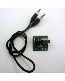
MT8870 DTMF dekóder Hangdekódoló modul telefon Távirányító kártya
349 Ft 712 Ft
Product Name: MT8870 DTMF Decoder Voice decoding module phone Remote control Board
Package:(Does not include UNO/MEGA2560):
1 PCS MT8870 DTMF Voice decoding module;
1 PCS 50cm Male to Male audio cable ( 3.5mm jack );
Description:
Onboard Complex Frequency Decoder IC MT8870D
Onboard 5 LED indicators for easy viewing output state
Universal 2.54mm pin
DC Power Supply Voltage : 5V(4.5V-5.5V)
Operating Temperature : -40- 85 °C
IO Drive : Current Maximum 10mA.
PCB Size : 25.4x25.4MM
This decoding module is for mobile and fixed telephone voice dialing decoding function
Designed specifically for ARDUIUO(UNO MEGA2560 etc) Board.also use for Breadboard MCU( C8051 C51 ZIGBEE CC2530 AVR PIC MSP430 STM32 STM8 ARM Xilinx Altera Lattice FPGA/CPLD)
Does not require any wiring, can be inserted directly into the UNO/MEGA2560/DUE board to use.
12 Digital outputs decode mobile and fixed telephone keys (0,1,2,3,4,5,6,7,8,9, * #).Another 4 Digital output(A,B,C,D) can use "DTMF Dial" PC Software control.
Dial-up -> A4 A3 A2 A1
Dial 1 -> 0 0 0 1
dial 2 -> 0 0 1 0
Dial 3 -> 0 0 1 1
Dial 4 -> 0 1 0 0
Dial 5 -> 0 1 0 1
Dial 6 -> 0 1 1 0
Dial 7 -> 0 1 1 1
Dial 8 -> 1 0 0 0
Dial 9 -> 1 0 0 1
Dial 0 -> 1 0 1 0
Dial * -> 1 0 1 1
Dial # -> 1 1 0 0
Dial A -> 1 1 0 1
Dial B -> 1 1 1 0
Dial C -> 1 1 1 1
Dial D -> 0 0 0 0
Arduiuo uno/mega2560 Code fragment:
After purchase, please contact me for complete code!
//*******************************************//
#include
int STD = A0;
int Q1 = A1;
int Q2 = A2;
int Q3 = A3;
int Q4 = A4;
....
//Check once every 5 ms
void dtmf_decode(void)
{
....
}
void setup()
{
.....
}
void loop()
{
//Complete the decoding
if(Decod_finished)
{
Decod_finished = 0;
Serial.print(" Activate : " );
switch(Q_dat){
case 1 : Serial.print("1 \n" ); break;
case 2 : Serial.print("2 \n" ); break;
case 3 : Serial.print("3 \n" ); break;
case 4 : Serial.print("4 \n" ); break;
case 5 : Serial.print("5 \n" ); break;
case 6 : Serial.print("6 \n" ); break;
case 7 : Serial.print("7 \n" ); break;
case 8 : Serial.print("8 \n" ); break;
case 9 : Serial.print("9 \n" ); break;
case 10 : Serial.print("0 \n" ); break;
case 11 : Serial.print("* \n" ); break;
case 12 : Serial.print("# \n" ); break;
....
}
.....
//****************************************************************************//
Typical application for Mobile phones((Does not include UNO/MEGA2560):
Typical application for DTMF Dial PC Software: -
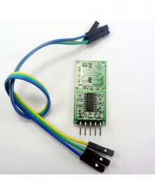
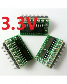
3x 3,3 V automatikus RS485–TTL232 konverter RF vezeték nélküli modulhoz, Wifi–RS-485 átalakító otthoni automatizálás
324 Ft 662 Ft
Product Name: 3x 3.3V Auto RS485 to TTL232 Converter for RF Wireless Module Wifi Bluetooth to RS-485 Transformation Home Automation Smart home
Package inlcuded:
3 PCS R411A01_3V3 DC 3.3V RS485 to LvTTL RS232 converter
Description:
Read and write automatic control RS485 TO RS232(3.3V TTL Logic level) converter
Operating Voltage : DC 3.3V
Logic level : 3.3V LvTTL Logic level
RS485 BUS IC : SP3485
Read and write automatic control IC :SM74HC04
7x 2.54MM pin,mini size.
Size(Does not include pin) : 17.9x11.7x2.8mm(very small)
Weight :1.2g(Very light)
Application
RS485 Temperature and humidity sensor
PTZ camera
LED controller
MODBUS RTU
RS485 Relay
485 sensor
automated manufacturing line
Wifi to RS485(ESP8266)
Bluetooth to RS485(HC-05/HC06)
Wireless Module to RS-485(HC-11)
Wiring Diagram:
-
2 db 2,6-5V - 5V dc dc fokozó konverter feszültségszabályozó Tápegység modul Arduino UNO MEGA2560 DUE Pro mini-hez
349 Ft 712 FtProduct Name : 2.6-5V TO 5V dc dc step up converter voltage regulator Power supply module for Arduiuo UNO MEGA2560 DUE Pro mini
Packing list:
2 PCS 5W 3V 3.3V 4.5V TO 5V Boost Step-UP Voltage Regulator Module
Description:
Input voltage 2.6~6V, output 5V (deviation -6% )
Maximum input current : 1.2A
Long-term work Current : 1A
Conversion efficiency : 79-91%
Start Voltage 2.6V, Output Current 51MA
INPUT 2.8V 1A; OUTPUT 5V 291MA
INPUT 3V 1A; OUTPUT 5V 480MA
INPUT 3.3V 1A; OUTPUT 5V 592MA
INPUT 3.7V 1A; OUTPUT 5V 650MA
INPUT 4.5V 1A; OUTPUT 5V 791MA
DC-DC Boost module working frequency 1.0MHZ.
Operating ambient temperature : -40~ 85 Degrees Celsius
2.54mm pin pitch,Arduiuo UNO DUE Breadboard FPGA/CPLD Development Board friendly.
Over Temperature Protection
Over Voltage Protection
Excluding Pin Size 20.5mm x 10.16mm x 5.6mm(Very small)
Weight : about 1.4g(Very light)
Applications:
MCU Development Board,FPGA/CPLD UNO MEGA2560 DUE 8051 AVR C8051 etc
RS485 PLC Modbus RTU
MP3 MP3 mobile phone charger
5V Relay board
5V LED
Wireless communication equipment
315M 433M Wireless remote controller
Attention :
This is a DC-DC voltage converter module,Must be noted when using:
1 Input voltage can not be greater than the maximum input range
2 Output power can not be greater than the maximum load for a long time
3 Input power must be greater than the output power, because the power consumption of the module itself
Q & A:
Q : Why output voltage is less than the nominal voltage
A : Input power supply power is too low.Test the input voltage with a multimeter, a t this time of the input voltage is very low -
DC 3-12V 433Mhz ASK OOK EV1527 Kódolt tanulási kód Adómodul otthoni betörésbiztonsági riasztórendszerhez Vezeték
344 Ft 703 Ft
Product Name : DC 5V 12V 1 CH 433Mhz ASK OOK PT2262 SC2262 Encoded Transmitter Module for GSM SMS Home Burglar Security Alarm System
Packing list:
1 PCS 433Mhz ASK OOK EV1527 Encoded Transmitter Module
Note:
This is our company wireless control receivers Accessories
If used in other applications, please read the the parameters carefully before purchase
Technical Data :
Power supply : DC 3-12V(Recommendation : 5V 12V)
Operating current: 9 mA;
Oscillation mode: SAW resonator;
Modulation mode: ASK/OOK;
Operating frequency : 433.92MHZ ;
Encoding IC : EV1527 OR compatiable IC;
Output power : 60MW;
RC Resistance : 300K;
Pin Description:
Typical applications:
-
2db 7W 2 az 1-ben Step-UP & Step-Down 3V 3.7V 5V 9V 15V 18V TO 12V DC-DC átalakító szabályozó modul PTZ IP kamerához
338 Ft 690 FtBelow item is powered by Canton-Power Ltd .
Product Name: 2pcs 7W 2 in 1 Step-UP & Step-Down 3V 3.7V 5V 9V 15V 18V TO 12V DC-DC Converter Regulator Module for PTZ IP camera
Packing list:
2 PCS DD2412SA_12V 2-24V TO 12V DC DC Step-UP & Step-Down Converter Module
Description:
Input voltage DC 2-24V, output DC 12V±4% (No-load voltage is 12-12.4V)
2 in 1 DC DC Boost-Buck Converter Module working frequency 1.2MHZ.efficiency 67% -89% .
Operating temperature range : -40~ 85 Degrees Celsius
Storage temperature range : -65~ 150 Degrees Celsius
2.54mm pin pitch,MCU Development Board Breadboard friendly.
Size : 21.4mm x 15.6mm x 5.8mm(Very small)
Weight : 2.2g(Very light)
Applications
Battery powered equipment
Breadboard Power Supply
electrical tools
Small power motors
Camera, Video camera
PLC RS485 Modbus Module
Toy car
Wifi Router
IP camera
LED Lighting
Wireless communication equipment
Instruments multimeter
Attention :
This is a DC-DC voltage converter module,Must be noted when using:
1 Input voltage can not be greater than the maximum input range
2 Output power can not be greater than the maximum load for a long time
3 Input power must be greater than the output power, because the power consumption of the module itself
Q & A:
Q : Why output voltage is less than the nominal voltage
A : Input power supply power is too low.Test the input voltage with a multimeter,a t this time of the input voltage is very low
-
5db bemeneti 2,5-5,5 V kimenet
324 Ft 662 Ft
Product Name : 5pcs Input 2.5-5.5V Output 0.6-5V Adjustable DC DC Converter Buck Module Synchronous Step-Down Regulator
Packing list:
5 PCS DD05AJSB Input 2.5-5.5V Output 0.6-5V Adjustable DC DC Converter Buck Module
But this product has the following defects:
1 10-30% rejection rate
2 Difficult to adjust output less than 1.8V
Description:
IC : FP6161
Input voltage DC 2.5~5.5V,Adjustable output 0.6~5.5V
Long time maximum output current 1A(5V to 3.3V)
Short time maximum output current 1.2A(5V to 3.3V)
Low Quiescent current: about 100uA
DC-DC Step-Down Converter module working frequency 1.5MHz. efficiency is 75-93% .
Size 16.7mm x 10.1mm x 5.5mm(Very small)
Weight : about 1g(Very light)
LDO Mode
The DD05AJSB’s maximum duty cycle can reach 100% .That means the driver’s main switch is
turn on through out whole clock cycle. Once the duty reaches 100% , the feedback path no longer
controls the output voltage. The output voltage will be the input voltage minus the main switch
voltage drop.
Over Current Protection
DD05AJSB limits the peak main switch current cycle by cycle. When over current occurs, chip will
turn off the main switch and turn the synchronous switch on until next cycle.
Short Circuit Protection
When the FB pin drops below 300mV, the chip will tri-state the output pin SW automatically. After
300us rest to avoid over heating, chip will re-initiate PWM operation with soft start.
Thermal Protection
DD05AJSB will shutdown automatically when the internal junction temperature reaches 150Degrees Celsius to
protect both the part and the system.
Attention :
This is a DC-DC voltage converter module,Must be noted when using:
1 Input voltage can not be greater than the maximum input range
2 Output power can not be greater than the maximum load for a long time
3 Input power must be greater than the output power, because the power consumption of the module itself
-
2 DB DC 3V 3.3V 3.7V 4.2V – 5V BE/KI kapcsolóval Step-UP Boost Modul ARDIUNOHOZ
305 Ft 623 FtModule No.: TB316-2
Packing list:
2 PCS 3-5V to 5V with Switch Boost Modules
Description:
Input voltage 2.8 ~ 5V, output 5V (deviation -5% )
Maximum input current: 1.5A
Long-term work Current: 1A
Conversion efficiency : 90%
PCB size : 25MM x 15MM
Start Voltage 2.8V, Output Current 100MA
INPUT 3V 1A; OUTPUT 5V 500MA
INPUT 3.3V 1A; OUTPUT 5V 590MA
INPUT 3.7V 1A; OUTPUT 5V 660MA
INPUT 4.5V 1A; OUTPUT 5V 800MA
This is with on/off switch voltage boost module.The master chip is FP6291GLR
Can used the input voltage (VIN or GND)control the switches,also use MCU IO control the switches.
Control current is very small, MCU IO port can be directly controlled. Including micro-controller : ARDIUNO MEGA2560 AVR STM32 ARM PIC AT89C51 STC MSP430 FPGA CPLD etc.
When the EN pin = GND(OR MCU LOW level),the boost module is working properly;
When the EN pin = VIN(or MCU HIGH level,3.3V/5V) OR Not Connected(or MCU High impedance),
the boost module into standby mode, stops working, the output voltage is 0V(Can measure the output voltage is 500~800MV, which is inductive output voltage,you does not have to bother).
Applications
Battery powered equipment
Wirels mouse, Wireless keyboard
Toys
Camera, Video camera
VCR
PDA
LED Lighting
Wireless communication equipment
MP3/MP4 player
Audio equipment
-
MT8870 DTMF dekóder vezérlő audio hang dekódoló tábla telefon modul az_Arduino MCU Banana Raspberry pi DUE UNO MEGA2560
323 Ft 659 FtProduct Name: MT8870 DTMF Decoder Controller Audio Voice Decoding Board Phone Module for Arduino MCU Banana Raspberry pi DUE UNO MEGA2560 NANO
Module No.: CE005
Package:(Does not include Arduino UNO/MEGA2560):
1 PCS MT8870 DTMF decoder module;
1 PCS Male to Male audio wire (3.5mm jack );
Description:
Onboard Complex Frequency Decoder IC MT8870DS
Onboard 5 LED indicators for easy viewing output state
DC Power Supply Voltage:5V(4.5V-5.5V)
Operating Temperature : -40- 85 °C
IO Drive : Current Maximum 10mA.
PCB Size : 25.4x25.4MM
This decoding module is for mobile and fixed telephone voice dialing decoding function
Designed specifically for ARDUINO Board.also use for other MCU(AVR PIC MSP430 STM32 ARM7/9/10/11 FPGA/CPLD)
Does not require any wiring, can be inserted directly into the UNO/MEGA2560/DUE board to use.
12 Digital outputs decode mobile and fixed telephone keys (0-9, * #).Another 4 Digital output(ABCD) can use "DTMF Dial" Software control.
Arduino uno/mega2560 Code fragment:
After purchase, please contact me for complete code!
//*******************************************//
#include
int STD = A0;
int Q1 = A1;
int Q2 = A2;
int Q3 = A3;
int Q4 = A4;
....
//Check once every 5 ms
void dtmf_decode(void)
{
....
}
void setup()
{
.....
}
void loop()
{
//Complete the decoding
if(Decod_finished)
{
Decod_finished = 0;
Serial.print(" Activate : " );
switch(Q_dat){
case 1 : Serial.print("1 \n" ); break;
case 2 : Serial.print("2 \n" ); break;
case 3 : Serial.print("3 \n" ); break;
case 4 : Serial.print("4 \n" ); break;
case 5 : Serial.print("5 \n" ); break;
case 6 : Serial.print("6 \n" ); break;
case 7 : Serial.print("7 \n" ); break;
case 8 : Serial.print("8 \n" ); break;
case 9 : Serial.print("9 \n" ); break;
case 10 : Serial.print("0 \n" ); break;
case 11 : Serial.print("* \n" ); break;
case 12 : Serial.print("# \n" ); break;
case 13 : Serial.print("A \n" ); break;
case 14 : Serial.print("B \n" ); break;
case 15 : Serial.print("C \n" ); break;
default : Serial.print("D \n" ); break;
}
.....
//****************************************************************************//
Typical application for Mobile phones((Does not include Arduino UNO/MEGA2560):
Typical application for DTMF Dial Software: -
2 DB Ultra kis fény DC 5V 1 csatornás DPDT relémodul dupla kapcsolótábla magas szintű IO vezérlés
349 Ft 712 FtTypical applications:
Automotive electronics
Audio and video equipment
lithium battery 18650
Motor,Toy car, boat, model aircraft
Emergency lighting
Product Name : 2PCS Ultra small light DC 5V 1 channel DPDT Relay Module double Switch Board High level IO Control
Packing list:
2 PCS DR21B01 one Channel DC 5V DPDT Relay Module
Description:
DR21B01 5VDC one Channel DPDT Relay Board
Operating Voltage : DC 4.5-5.5V(5V)
Operating Current(Relay ON): 36MA
Standby Current(Relay OFF) : <1MA
Input control signal voltage:
0V - 0.6V Low stage (relay is OFF),
0.6V – 2.5V (unknown state).
2.5V - 24V High state (relay is ON).
Input control signal high state current:
2.5V: 0.15mA
5V: 0.4mA
12V: 1.2mA
20V: 2mA
Relay Load : 1A 125VAC;2A 30VDC
Size : 22.86x18x14
Weight :6g
Schematic:
-
2 db 2 az 1-ben DC 3 V 3,3 V 3,7 V 6 V 9 V 12 V - 5 V DC/DC Boost-Buck átalakító tápegység modul Arduino UNO Nano DUE AVR
338 Ft 690 FtBelow item is powered by Canton-Power Ltd .
Product Name: 2pcs 2 in 1 DC 3V 3.3V 3.7V 6V 9V 12V to 5V DC/DC Boost-Buck Converter Module for Arduiuo UNO Pro mini Nano DUE AVR STM32
Packing list:
2 PCS DD2412SA_5V 2-24V TO 5V DC DC Boost-Buck Converter Module
Description:
Input voltage DC 2-24V, output DC 5V±5% (No-load voltage is 5-5.4V)
2 in 1 DC DC Boost-Buck Converter Module working frequency 1.2MHZ.efficiency 70% -90% .
Operating temperature range : -40~ 85 Degrees Celsius
Storage temperature range : -65~ 150 Degrees Celsius
2.54mm pin pitch,for MCU Development Board Breadboard friendly.
Size : 21.4mm x 15.6mm x 5.8mm(Very small)
Weight : 2.2g(Very light)
Applications
Battery powered equipment
Breadboard Power Supply
ARM STM32 AVR PIC FPGA CPLD Board
UNO Pro mini Nano DUE AVR STM32
Small power motors
Camera, Video camera
Toy car
power bank
Phone PDA
LED Lighting
Wireless communication equipment
Audio equipment
Attention :
This is a DC-DC voltage converter module,Must be noted when using:
1 Input voltage can not be greater than the maximum input range
2 Output power can not be greater than the maximum load for a long time
3 Input power must be greater than the output power, because the power consumption of the module itself
Q & A:
Q : Why output voltage is less than the nominal voltage
A : Input power supply power is too low.Test the input voltage with a multimeter,a t this time of the input voltage is very low
-
2x dc dc konverter fokozó boost modul 5v-9v Arduino Breadboard Relay LED 315M 433M vezeték nélküli távirányítóhoz
323 Ft 659 FtProduct Name : 2x dc dc converter step up boost module 5v to 9v for Ardiuno Breadboard Relay LED 315M 433M Wireless remote control
Packing list:
2 PCS 5W 3V-6V TO 9V Boost Step-UP Voltage Regulator Module
Description:
Input voltage 2.8~6V, output 9V (deviation -5% )
Maximum input current : 1.2A
Long-term work Current : 1A
Conversion efficiency : 81-91%
Start Voltage 2.8V, Output Current 60MA
INPUT 3V 1A; OUTPUT 9V 290MA
INPUT 3.3V 1A; OUTPUT 9V 330MA
INPUT 3.7V 1A; OUTPUT 9V 360MA
INPUT 4.5V 1A; OUTPUT 9V 440MA
INPUT 5V 1A; OUTPUT 9V 490MA
INPUT 6V 1A; OUTPUT 9V 590MA
DC-DC Boost module working frequency 1.0MHZ.
Operating ambient temperature : -40~ 85 Degrees Celsius
Over Temperature Protection
Over Voltage Protection
2.54mm pin pitch,Arduiuo UNO DUE Breadboard FPGA/CPLD Development Board friendly.
Excluding Pin Size 20.5mm x 10.16mm x 5.6mm(Very small)
Weight : about 1.4g(Very light)
Applications:
MCU Development Board,FPGA/CPLD UNO MEGA2560 DUE 8051 AVR C8051 etc
PLC Modbus RS485
Network equipment/Router
VCR
PDA
LED Lighting
9V Relay board
Wireless communication equipment
315M 433M Wireless remote controller
Attention :
This is a DC-DC voltage converter module,Must be noted when using:
1 Input voltage can not be greater than the maximum input range
2 Output power can not be greater than the maximum load for a long time
3 Input power must be greater than the output power, because the power consumption of the module itself
Q & A:
Q : Why output voltage is less than the nominal voltage
A : Input power supply power is too low.Test the input voltage with a multimeter, a t this time of the input voltage is very low -
Szín: Csak vezérlő - DC 12V akvárium akvárium automatikus táp vezérlő Vízszint érzékelő mágnesszelep Magas Közép
326 Ft 666 Ft
Product Name: DC 12V Fish tank Aquarium automatic supply controller Water Level Sensor Solenoid High Mid Low level LED indicator Board
Package inlcuded:
1 x DC 12V LOW MID HIGH indicators LC66C01 Automatic pumping and pouring controller Module(The probe is 2P Male XH2.54mm Pitch Wire Cable, which can be purchased separately or prepared by yourself.)
Description:
1 Working voltage: DC 12V
2 Standby current 6MA
3 Working current 32MA
4 Size: 63mm X 29mm X 19mm
5 Weight: 20 g
6 Maximum load: 10A / 250VAC, 10A / 125VAC, 10A / 30VDC, 10A / 28VDC, 10A / 12VDC
There are two purposes for connecting the NO and NC ports of the relay:
The water pump is connected to the COM NC port to automatically fill the water tower
The water pump is connected to the COM NO port to automatically pump water from the water tower
Note:
1 Package does not contain probe (wire).2P Male XH2.54mm Pitch Wire Cable can be used as a probe,which can be purchased separately or prepared by yourself.
2 For safety, use an DC power supply with good isolation
Application
Home water tower automatic water supply system
Aquarium Fish tank Water Changer System
Fill the water tower automatically
Automatic pumping from water tower
Conductive liquid automatic control
Automatic feeding system for poultry and livestock
Farm automatic water supply system
And other occasions that require automatic water supply and water exchange.
Solenoid valve water pump motor automatic control
Interface description:
HIGH : Upper limit probe
LOW : Lower limit probe
DC : Power of positive
DC- : Power of negative
NC : Relay normally closed contact
COM : Relay common contact
NO : Relay normally open contact
Working principle(Fill the water tower automatically):
The water level rises: When the water level is lower than the ''Low level'', the water pump starts to supply water to the water tower; when the water level is higher than the ''High level'', the water pump stops supplying water.
Water level reduction: When the water level is lower than the ''High level'', the water pump does not work and the water level continues to decrease. When the water level is lower than the ''Low water level'', the water pump starts to supply water to the water tower.
Working principle(Automatic pumping from water tower):
Contrary to ''Fill the water tower automatically''
Make the probe(Need to be purchased separately):
1 Prepare 2PCS(or more) XH2.54MM wires
(You can prepare this kind of wire by yourself, or buy it from our shop)
2 Multiple wires can be spliced to lengthen the probe length.
(Please do waterproof treatment at the splicing.)
3 Please cut the female interface short and keep a distance of 5-10MM
(This prevents water droplets from sticking to the probe. ) -
Szín: Csak szonda - DC 12V akvárium akvárium automatikus táp vezérlő Vízszint érzékelő mágnesszelep Magas Közép
84 Ft 172 Ft
Product Name: DC 12V Fish tank Aquarium automatic supply controller Water Level Sensor Solenoid High Mid Low level LED indicator Board
Package inlcuded:
1 x DC 12V LOW MID HIGH indicators LC66C01 Automatic pumping and pouring controller Module(The probe is 2P Male XH2.54mm Pitch Wire Cable, which can be purchased separately or prepared by yourself.)
Description:
1 Working voltage: DC 12V
2 Standby current 6MA
3 Working current 32MA
4 Size: 63mm X 29mm X 19mm
5 Weight: 20 g
6 Maximum load: 10A / 250VAC, 10A / 125VAC, 10A / 30VDC, 10A / 28VDC, 10A / 12VDC
There are two purposes for connecting the NO and NC ports of the relay:
The water pump is connected to the COM NC port to automatically fill the water tower
The water pump is connected to the COM NO port to automatically pump water from the water tower
Note:
1 Package does not contain probe (wire).2P Male XH2.54mm Pitch Wire Cable can be used as a probe,which can be purchased separately or prepared by yourself.
2 For safety, use an DC power supply with good isolation
Application
Home water tower automatic water supply system
Aquarium Fish tank Water Changer System
Fill the water tower automatically
Automatic pumping from water tower
Conductive liquid automatic control
Automatic feeding system for poultry and livestock
Farm automatic water supply system
And other occasions that require automatic water supply and water exchange.
Solenoid valve water pump motor automatic control
Interface description:
HIGH : Upper limit probe
LOW : Lower limit probe
DC : Power of positive
DC- : Power of negative
NC : Relay normally closed contact
COM : Relay common contact
NO : Relay normally open contact
Working principle(Fill the water tower automatically):
The water level rises: When the water level is lower than the ''Low level'', the water pump starts to supply water to the water tower; when the water level is higher than the ''High level'', the water pump stops supplying water.
Water level reduction: When the water level is lower than the ''High level'', the water pump does not work and the water level continues to decrease. When the water level is lower than the ''Low water level'', the water pump starts to supply water to the water tower.
Working principle(Automatic pumping from water tower):
Contrary to ''Fill the water tower automatically''
Make the probe(Need to be purchased separately):
1 Prepare 2PCS(or more) XH2.54MM wires
(You can prepare this kind of wire by yourself, or buy it from our shop)
2 Multiple wires can be spliced to lengthen the probe length.
(Please do waterproof treatment at the splicing.)
3 Please cut the female interface short and keep a distance of 5-10MM
(This prevents water droplets from sticking to the probe. )